chaPter
1
soldering—definition
and differences
SOLDER IS A FUSIBLE METAL ALLOY with a melting point (or range) of 90 to 450 °C (190 to 840 °F), used in a process called soldering, in which it is melted to join metallic surfaces (which of course must themselves have higher melting temperatures so that they remain solid when the solder is melted). It is especially useful in electronics and plumbing. Alloys that melt between 180 and 190 °C (360 and 370 °F) are the most commonly used. If alloys with melting points above 450 °C (840 °F) are used, the process is no longer called soldering but brazing.
Solder can contain lead and/or flux, but in many applications, solder is
now lead- free.
The word solder comes from the middle- English word soudur, via Old French solduree and soulder, from the Latin solidare, meaning “to make solid.”
1�1 Soldering and history
Soldering is a joining process that uses a filler metal to join parent ma -terials that remain solid. By convention, as noted previously, soldering
uses filler alloys with melting temperatures below 450 °C (840 °F). Sol
-dering may or may not use a fluxing agent. (Fluxing agents, also called fluxes, are used to help in cleaning the interface but may leave a residue.)
Because processing temperatures are lower than for brazing, soldering has
been the standard assembly procedure for electronic equipment. Local
heating of the joint can be done with a torch, a soldering iron (local resis-tance heating), induction heating, a laser, or a hot air gun. Assemblies can
also be heated in an oven. There are also diffusion bonding techniques that
The bond between solder and base metal is more than adhesion or me-chanical attachment, although these do contribute to bond strength. Rather, the essential feature of a soldered joint is that a metallurgical bond is
pro-duced at the filler- metal/base- metal interface. The solder reacts with a
small amount of the base metal and wets the metal by forming
intermetal-lic compounds. Upon solidification, the joint is held together by the same
attraction between adjacent atoms that holds a piece of solid metal to-gether. The ease of wetting (discussed later) is related to the ease with
which this solvent action occurs. The presence of the base- metal/filler-
metal reaction is one factor in the wetting action of the solder. Other fac-tors include surface cleanliness and solder surface tension (that is,
capil-lary flow).
Soldering is an ancient joining method. It is mentioned in the Bible (Isaiah 41:7), and there is evidence of its use in Mesopotamia 5000 years ago, well before the time of Cleopatra, as well as later in Egypt, Greece, and Rome (Ref 1.2). Pliny the Elder, in his Historia Naturalis, written 2000 years ago, mentions (in Chapter XLVIII of Book XXXIV) that the
solder connections of the pipes of the Roman aqueducts were made with a
mixture called tertiarium, an alloy of two parts lead and one part tin. The earliest solders were alloys found in nature, which meant that only a few solders, with a severely limited range of properties, were available. Be-cause these early solders were generally used to join jewelry parts or to attach handles to decorative vessels, the primary concerns were appear-ance, melting point, and, to a lesser degree, strength. The materials were rare and costly, and the work was done by highly skilled artisans. There-fore, only the wealthy could hope to own articles made in this way.
It has been only in the last two centuries that some metals have become cheap and that strictly utilitarian parts are soldered. In the 1800s, low- cost steels made household tinware (which is made not of tin but of tin- plated steel, or tinplate) practical for most families, and the “tinner” became the common solder practitioner. The emergence of electrical technology
re-quired the attachment of electrical leads, which became the most common
application of solders. This meant that the electrical properties of solders became a consideration; the electrical continuity of the joint was of para-mount importance, where jewelry and utensils had emphasized strength and appearance. The use of solders for electrical attachments also involved simple mechanical joints and repetitive operations. The cost of the materi-als was much reduced, because lead- tin solders were usually used. Even
today (2013), it is customary to give the tin content first when designating
a solder (for example, 40/60 solder refers to a solder that is 40% Sn and 60% Pb). These new criteria promoted a new type of artisan whose skills were more oriented to engineering and production than to aesthetics, al-though most of the work was still done manually.
By the 20th century, metallurgical science had developed to the point
structural applications. The emerging electronics industry required solders
with the following properties:
• Compatibility with copper (especially with respect to alloying behav-ior and melting temperatures)
• Good electrical conductivity
• Workability to enable factory workers to rapidly form low- cost, reli-able soldered joints
Engineers now have formal rules to govern the design of joints used in
various applications to ensure the required levels of strength. The materi -als and processes involved in soldering have now become established in engineering practice (Ref 1.3–1.7).
1�2 Fundamentals—alloy Formation and
Phase Diagrams
Every pure metal has a crystalline state and a well- defined melting
temperature. Metals also possess reasonable ductility and strength. Met-als are excellent electrical conductors compared to ceramics or plastic polymer materials. Thermal conductivity generally follows electrical conductivity (that is, a good electrical conductor is usually also a good thermal conductor).
The best means for portraying the behavior of alloys is the equilib
-rium phase diagram (also called equilib-rium diagram or constitution diagram), which represents the phases present under equilibrium con-ditions in a given alloy system. Phase diagrams are plots of alloy equi -librium composition versus temperature. The diagrams are generally
worked out by measuring the melting and solidification behaviors of
alloys of dif ferent compositions and then observing the resultant micro-structures. Understanding phase diagrams is essential to working effec-tively with solders, because they are used to predict solder microstruc-ture and behavior.
When two or more metals are melted together, they form an alloy that
behaves as a unique material with specific properties that can significantly
differ from the properties of the individual pure metals. Alloy properties depend on the atomic structure and thermal- physical properties of its con-stituent elements. For example, the addition of tin to lead will result in an alloy that has a lower melting point than either tin or lead—perhaps more surprisingly, so will the addition of lead to tin. The physical and mechani-cal properties of the alloys will also differ from the properties of the pure metals.
Some combinations of metals, such as gold and silver, form alloys sim-ply because they are mutually soluble; that is, each can be dissolved in the other. An alloy formed in such a way is called a solid solution.
Two metals that have greater differences in their basic properties may have limited solubility in one another and may not dissolve completely. One such combination is silver and copper. Combining these two forms a
eutectic alloy, which, by definition, is an alloy with a melting temperature significantly lower than either of its component metals alone. In addition, the eutectic alloy composition itself exhibits a unique type of melting and solidification behavior: melting and solidifying at a single, specific tem -perature just as a pure metal does. The solid eutectic alloy is a mixture comprising two phases, rather than a solid solution. Eutectic alloy struc-tures and behavior are of critical importance in soldering.
The concepts behind the use of soldering are as follows:
• Solder is used to hold two (or more) conductors in electrical contact with each other.
• Solder is not used to make the electrical contact.
• Solder is not used to provide the main mechanical support for a joint.
• Solder is used to encapsulate a joint, prevent oxidation of the joint, and provide minor mechanical support for a connection.
1�3 Process Description and Wetting
In the soldering process, heat is applied to the parts to be joined, caus-ing the solder to melt and to bond to the workpieces in an alloycaus-ing process called wetting. In the soldering of stranded wire, the solder is drawn up into the wire by capillary action in a process called wicking. Capillary ac-tion also takes place when the workpieces are touching or very close
to-gether. The joint strength is dependent on the filler metal used. A soldered
joint has electrical conductivity and is water- and gastight (Ref 1.8). Solder wetting necessarily involves the metallurgical reactions between
the filler metal and the base metal. This interaction at the solder/base-
metal interface can result in a covalently bonded layer of a material called an intermetallic compound. Examples include tin and gold (AuSn4), cop-per and tin (Cu6Sn5 and Cu3Sn), or nickel and tin (Ni3Sn4). Unlike the metallic bond of metals and alloys, the covalent bond causes the interme-tallic to be hard and brittle, to have a high melting point, and to be resis-tant to chemical attack. Excessively hard intermetallic layers can jeopar-dize the physical and mechanical integrity of soldered joints.
1�4 Intermetallics in Solders
Many different intermetallic compounds are formed during solidifying of solders and during their reactions with the solder surfaces (Ref 1.9).
The intermetallics form distinct phases, usually as inclusions in a duc-tile solid- solution matrix, but they can also form the matrix itself and con-tain metal inclusions or form crystalline matter with different
intermetal-lics. Finely distributed intermetallics in a ductile matrix yield a hard alloy; coarse structure gives a softer alloy. A range of intermetallics often forms between the metal and the solder, with a higher proportion of metal on one side and of solder on the other, for example, forming a structure of Cu- Cu3Sn- Cu6Sn5- Sn (Table 1.1).
Layers of intermetallics can thus form between the solder and the par-ent material. These layers may cause any of several problems. They may cause mechanical unreliability in the form of weakening and brittleness; they may increase the electrical resistance of the joint; or they may be susceptible to electromigration and the formation of voids. The gold- tin intermetallic layer, for example, is responsible for the poor mechanical reliability of tin- soldered gold- plated surfaces when the gold plating does not completely dissolve in the solder.
Gold and palladium readily dissolve in solders. Copper and nickel tend
to form intermetallic layers during normal soldering profiles. Indium
forms intermetallics as well.
Indium- gold intermetallics are brittle and occupy approximately four times more volume than the original gold. Bonding wires are especially susceptible to indium attack. Such intermetallic growth, together with thermal cycling, can lead to failure of the bonding wires (Ref 1.11).
Copper plated with nickel and gold is often used. The thin gold layer facilitates good solderability of nickel because it protects the nickel from oxidation; the layer must be thin enough to dissolve rapidly and completely so that bare nickel is exposed to the solder (Ref 1.12).
Lead- tin solder layers on copper leads can form copper- tin intermetallic layers; the solder alloy is then locally depleted of tin and forms a lead- rich layer. The tin- copper intermetallics then can become exposed to oxidation, resulting in impaired solderability (Ref 1.13).
Two processes play roles in a soldered joint formation: interaction be-tween substrate and molten solder, and solid- state growth of intermetallic
compounds. The base metal dissolves in the molten solder in a quantity
that depends on its solubility in the solder. The active constituent of the
table 1�1 Intermetallics in solders
Tin Lead Indium
Copper Cu4Sn, Cu6Sn5(a), Cu3Sn(b), Cu3Sn8 … Cu3In, Cu9In4
Nickel Ni3Sn, Ni3Sn2, Ni3Sn4(c), NiSn3 … Ni3In, NiIn, Ni2In3, Ni3In7
Iron FeSn, FeSn2(d) … …
Indium In3Sn, InSn4 In3Pb …
Antimony SbSn … …
Bismuth … BiPb3 …
Silver Ag6Sn, Ag3Sn … Ag3In, AgIn2
Gold Au5Sn, AuSn, AuSn2, AuSn4(e) Au2Pb, AuPb2 AuIn, AuIn2(f)
Palladium Pd3Sn, Pd2Sn, Pd3Sn2, PdSn, PdSn2, PdSn4 … Pd3In, Pd2In, PdIn, Pd2In3
Platinum Pt3Sn, Pt2Sn, PtSn, Pt2Sn3, PtSn2, PtSn4 Pt3Pb, PtPb, PtPb4 Pt2In3, PtIn2, Pt3In7
(a)Common on solder-copper interface; forms preferentially when excess of tin is available; in presence of nickel, (Cu,Ni)6Sn5
com-pound can be formed. (b) Common on solder-copper interface; forms preferentially when excess of copper is available; more thermally stable than Cu6Sn5; often present when higher-temperature soldering occurs. (c) Common on solder-nickel interface. (d) Very slow
formation. (e) Phase brittle; forms in excess of tin; detrimental to properties of tin-base solders to gold-plated layers. (f) Forms on the boundary between gold and indium-lead solder; acts as a barrier against further dissolution of gold. Source: Ref 1.10
solder reacts with the base metal at a rate that depends on the solubility of the active constituents in the base metal. The solid- state reactions are more complex; the formation of intermetallics can be inhibited by chang-ing the composition of the base metal or the solder alloy, or by uschang-ing a suitable barrier layer to inhibit diffusion of the metals (Ref 1.14).
All electrical/electronic applications require soldering to a base metal.
This base metal can be the metal that makes up the physical structure of the electrical/electronic lead, or it can constitute an underplate or a barrier metallization. In all cases, the metal must be metallurgically wettable by the solder.
Intermetallic compounds are more like chemical compounds than like metallic alloys. In soldering, intermetallic compounds in thin and uniform layers represent the “glue” that forms the structural bonds between the solder and the metal being soldered. Therefore, the base metal must be metallurgically compatible with at least one of the metallic components in the solder.
This intermetallic compound formation can occur by a solid/liquid re -action (molten solder against a solid base metal) or a solid- state diffusion reaction (solder plate against a solid base metal). In either case, the solder
and base metal react to form a film of intermetallic compound between the
two metals, which holds them together. For example, when tin- lead sol-ders are used with copper, a widely used base metal, the tin reacts with the copper. Two intermetallics discussed previously can form in this metal-lurgical system. The compound Cu6Sn5 will primarily form during liquid/ solid reactions. In addition, Cu6Sn5 continues to grow in the solid state at elevated temperatures. The compound Cu6Sn5 will be present during any solid- state reactions.
Every base- metal solder system forms at least one such compound. For example, soldering to nickel instead of copper will result in t nickel in-termetallics (Ni3Sn4) at the interface. The Ni3Sn4 layer grows very slowly
in the solid state and is typically difficult to observe.
The ability of base metal to form a stable intermetallic compound layer with a solder limits the number of base- metal/solder combinations that are suitable for the majority of applications. The formation kinetics of
in-termetallic layers must permit the thorough wetting of the solder for effi -cient processing. Therefore, some metals are more readily soldered than others.
1�5 Passivation
The passivation characteristic of the base metal is another factor to be taken into account. In passivation, a material forms an outer corrosion layer that shields it against its environment and causes it to become more chemically passive. Such a layer forms a physical barrier against metal-lurgical wetting. Before the base metal can be metalmetal-lurgically wetted by
the solder, the solder must make intimate contact, on an atomic scale, with
clean base metal. Passivation layers are normally oxide films that may be
only a few atomic layers thick. Even so, they affect the ability of the sol-der to contact the base metals unsol-derneath them. Many metals will
passiv-ate extremely rapidly. Even when very active fluxes are used, stainless
steel becomes unwettable after only a short exposure to atmosphere at room temperature.
Another issue is the chemical and mechanical stability of a passivation layer. Because the passivation layer that forms on solder is chemically
weak, it can be reduced by weak fluxes. Nickel, on the other hand, forms a passivation film that is strong both chemically and mechanically. It is adherent to the base metal and requires much stronger fluxes to remove
chemically.
1�6 Solderability
Solderability, or the ease with which a material can be joined by a given soldering method, is a property of electronic and other components that is
crucial both to the efficiency of manufacture and to the reliability of the
product (Ref 1.15). Good component solderability is important for three basic reasons:
• It allows the use of less active fluxes, thereby reducing the requirement for cleaning flux residues. (This is an environmental benefit. In addi
-tion, the removal of flux residue eliminates potential corrosion prob -lems caused by that residue.)
• It produces greater first- pass soldering yields and consequently re
-quires less hand working of the soldered joints (important because re -working can reduce the fatigue performance of a joint, compared with
a successful first- pass joint).
• It results in a greater uniformity of solder fillet, with a geometry that is
close to the ideal for maximum fatigue performance.
Solderability depends on the wettability of the two surfaces being joined. Poor component solderability can, to some extent, be overcome by
using more active fluxes, but the trend toward denser component packing makes it difficult to remove flux residue after assembly; therefore, less active fluxes are preferable. Environmental concerns (such as those about the use of chlorofluorinated carbon solvents) are also reasons to avoid fluxes. The cost of inspection, testing, and component replacement or sol
-der fillet rework increases the desirability of defect- free sol-dering. There -fore, solderability is an increasingly important manufacturing issue.
The solderability of a component is a complex processing parameter. The relationship between wettability and solderability represents a major unresolved gap in the understanding of the soldering process. Wettability
can be measured directly. Solderability, however, cannot be directly
mea-sured in a quantifiable way, and its relationship to wettability has not yet been explicitly defined.
There are three important aspects to solderability:
• Thermal demand
• Wettability
• Resistance to soldering heat
The thermal characteristics of the component must allow the joint to be
heated to the soldering temperature within the specified time. To be sol -derable, surfaces must allow the molten solder to wet and spread during
the available time without subsequent dewetting (a phenomenon discussed
later). The soldering heat and the induced thermal stresses associated with it must not affect the functioning of the components. Each of these aspects
of solderability can be engineered to fit a particular application by the suit -able choice of solder alloys and process control parameters. With regard to design for performance, the aspect that imposes the strictest restraints is component wettability.
When discussing the wetting characteristics of a surface by molten sol-der, there are two important factors to consider: the extent of wetting and the rate of wetting (Ref 1.15). The extent of wetting (as indicated by the
contact angle) is an equilibrium governed by the laws of thermodynamics and depends on the surface and interfacial energies involved at the liquid/
solid interface (Fig. 1.1) (Ref 1.16). The rate of wetting (that is, how rap-idly the solder wets and spreads) is governed by the thermal demand of
the system, the ability of the heat source to supply heat, the efficacy of the flux, the viscosity of the solder, and the chemical reactions that occur at
the interfaces.
Fig� 1�1
Liquid solder droplets on a solid surface under two conditions. (a) Wetting. (b) nonwetting. arrows indicate surface tension. source: ref 1.16The physics of wetting is governed by Young’s equation (also known as Young- Depre equation, because Young described the problem quantita -tively in 1805 and Depre put it in mathematical terms in 1869). A detailed
discussion of the aforementioned equations and wetting can be found in
Ref 1.16.
A typical example of nonwetting occurs when a liquid metal droplet is
placed on a nonmetallic surface, such as copper oxide. Because there are
no metallic bonds at the oxide surface, the liquid metal will have little
tendency to interact with that surface. The metal droplet will behave as though it is repelled and will try to ball up to minimize the area of contact
with the nonmetallic surface. One method for quantifying wettability is to
observe the behavior of solder droplets on the metal surface. The contact
angle formed between the surface of the liquid solder and the surface of
the solid can be measured (Fig. 1.1). If the solder droplet forms a contact angle of less than 90°, then the solder is said to wet the metal. If the angle is greater than 90°, the solder is nonwetting. This is one method used to
qualitatively assess solderability.
The formation of intermetallic compounds can affect Young’s equation because it alters the value of the solid- liquid phase. The influence of this term has been recognized (Ref 1.15), but the magnitude of its influence has not yet been calculated quantitatively.
The surfaces of a metal crystal have a higher free energy than the bulk
of the crystal, because of the existence of unsatisfied metallic bonds. When a liquid metal or alloy is brought into contact with this solid sur
-face, the liquid will proceed to interact with the solid to satisfy those dan -gling surface bonds and thus reduce the surface free energy of the system.
To the extent that a liquid solder can satisfy the surface bonds, it will wet
the solid metal and spread across its surface. If no exchange of bonding energy takes place, then wetting will not occur and the solder will tend to ball up on the surface of the solid, minimizing the area of contact between
liquid and solid.
1�7 Joint Design and Guidelines
Soldered joints provide both electrical connection and structural sup-port in the microelectromechanical systems and electronics industry. Sol-ders can join dissimilar materials of varied thickness. Proper joint design can bring the strength of the joint near that of the parent material. Typi-cally, the processing temperature is slightly above the melting temperature (Tm) of the solder, and the surface temperature usually must be below Tm.
Because soldering has a 5000 year history, the process has subtleties that are often not appreciated. To optimize results, the choice of alloy, the form of alloy (wire, rings, foil, paste), surface preparation (cleaning and
coating), flux (if any), jigging, heat source, joining atmosphere, heating cycle, and posttreatment each play a significant role. Solder alloys are also
Joints should be designed to fulfill the requirements of the finished as
-sembly as well as to permit the application of the flux and solder. Joint design should maintain proper clearance during heating and upon solidifi
-cation of the filler metal. Sometimes the units can be crimped, clinched, wrapped, or otherwise held together, but in some cases, special fixtures
may be needed.
The selection of a joint designed for a specific application will primar
-ily depend on the service requirements of the assembly. It may also de -pend on such factors as the heating method to be used, the fabrication
techniques used prior to soldering, the number of items to be soldered, and
the method used to apply the solder. In general, solders have low strength when compared with the metals they are used to join. Therefore, the sol-dered joint should be designed to avoid dependence on solder strength. The necessary strains can be provided by shaping the parts to be joined so
that they engage or interlock, requiring the solder only to bond, seal, and
stiffen the assembly.
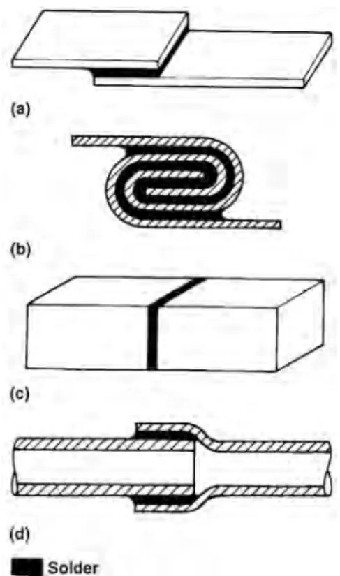
Figure 1.2 shows joint designs commonly used for soldering applica-tions. The lap joint and the lock seam joint are used when soldering sheets. Lap joints are also used to join pipes. The lap joint should be used when-ever possible because it offers the best chance to obtain joints with
maxi-mum strength; it should also be used whenever a seal is required. Butt
joints should be avoided whenever possible.