PID Controller Design for Cruise Control
System using Particle Swarm Optimization
Ahmed Raheem Abdulnabi
Businesses Informatics College, University of Information Technology and Communications, Baghdad, Iraq.
Abstract:This paper presents a design of a Proportional-Integral-Derivative (PID) controller for automobile cruise control system. The parameters of the PID controller, which are the proportional ( ), derivative ( ) , and integrator ( ), have been selected using Particle Swarm Optimization (PSO) algorithm. In this study, the overall system performance has been compared with other predesigned controllers (conventional PID, Fuzzy logic PID, state space, and Genetic algorithm based PID controller). The simulation result illustrates that PSO based PID controller gives the best response in terms of settling time, rise time, peak time, and maximum overshot. The robustness analysis shows that the system is robust despite the deviations in some of the system parameters.
Keywords:Cruise Control; PID; PSO, GA, Robustness Analysis.
1.
Introduction
Nowadays, the cruise control system has become a common feature of the modern vehicles [1]. Cruise control system helps in providing the comfortability to the driver while driving in a long-distance travel. Using cruise control system, travelling on the highways has become easier than before, because it reduces the mental and physical stress that caused from regularly monitoring the speed of the vehicle and frequently pressing the gas pedal to maintain the speed [2]. The main functionality of the cruise control system is to maintain the speed of the vehicle at a set-point previously set by the driver. The Cruise control system has a push button that enables the driver to set a reference speed. Then, the system will compare the actual speed with the reference point and adjust the throttle so as to equalize the actual speed with the reference point.
Proportional-Integral-Derivative (PID)
controller
provides a great way to stabilize systems. It has the ability to change the response of the system to be stable and reliable when it is used for controlling systems. PID controller has three parameters: proportional (Kp),
integral (Ki), and derivative (Kd). These three
parameters are tuned in a manner so the system will be stabilized according to predefined criteria. Furthermore, most of the feedback systems are controlled by using
PID controller. Also, PID controller can be
implemented as PID, PI, or PD. So, it helps the researchers with diverse choices to work with it [3].
Particle Swarm Optimization (PSO) is a
metaheuristic algorithm which is used to optimize
given problem. PSO is used to solve complex mathematical models equations which are difficult to handle using the conventional methods [4]. Many researches have been through the modelling of automobile cruise control system [5][6]. Some of the researchers designed controllers to enhance the functionality of the cruise control system. A PID controller is used for this purpose[6][7]. The researchers used different methods to tune the parameters of the PID controller such as state space, fuzzy logic, and genetic algorithm (GA). The state space, and fuzzy logic based PID controller showed a fair output response. The GA based PID Controller showed a good output response. However, a PSO based PID controller has not yet been investigated. This paper proposes a tuned PID controller that stabilize the unstable cruise control system and a PSO algorithm has been used to optimize the PID controller parameters in accordance to predefined specifications. The objective of this study is to minimize the settling time and overshoot of the cruise control system. Compared with earlier studies that proposed a conventional PID, Fuzzy [8], state space [9] based controllers, and genetic algorithm based PID controller [7]. the PSO based controller gives a better transient response. A simulation has been handled using m-file code and the values are confirmed.
2.
Cruise Control System
The cruise control system is a device that regulates and maintains the speed of the vehicle at a set point. The
control system then maintains the speed to the given point of the command signal. There are two main disturbances affect on the constant speed, first is the wind resistance against the velocity of the vehicle, and second is the slope of the road which generates the gravity pull effect. Figure (1) shows a schematic diagram of a vehicle on a sloped road
Figure (1): A schematic diagram for a vehicle on a sloped road
The cruise control system generates a control signal and delivers this signal to the actuators that controls the vehicle throttle valve, thus controls the fuel injection in the engine and providing a constant speed.
The transfer function of the cruise control system is[10]:
…………..(1)
Also, A delay time
………(2)
Where is the aerodynamic drag coefficient, is the
mass of the vehicle including passenger(s) and is the velocity, is the force saturation constant, and is the time constant of the first order lag[6]. After substituting all the constants and equation (2) in equation (1) we get[6]:
…………...(3)
3.
PID Controller
Proportional-Derivative-Integral controller is the most common controller used in the feedback control system because of its simplicity and easiness of use. The PID controller has the ability to compensate several practical processes [11]. The general Formula of the PID controller is
:
………..(4)
Where = proportional gain
= integral gain
= derivative gain
The following schematic diagram, which is figure (2), shows the configuration of a PID controller for a unity feedback system
Figure (2): PID Controller Schematic Diagram
4.
Particle Swarm Optimization
Algorithm
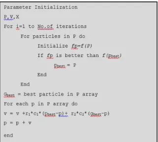
Particle swarm optimization is a nature inspired technique developed by Kennedy-Eberhart [12]– [15]. PSO is a simple and powerful optimization algorithm and it is successfully applied to enormous applications in various fields of science and engineering. Initially, the PSO system has randomly selected values of solutions called population. Each single solution is called a particle. Furthermore, for each particular particle, there is a velocity which is randomly selected. Another, there is a position called best position (Pbest) for each particle. The particles move and keep tracking of the Pbest, and there is a fitness value for each Pbest. The greatest fitness value is called the global best (Gbest). There are two main equations in the algorithm of the PSO, velocity and position vectors [16] and they are respectively shown below in equations (5) and (6).
( )
……….(5)
………….(6)
Where and are two random vectors, and their values lies between 0 and 1. The parameters and represent the acceleration constants or the learning parameters, and they are typically taken as ≈ ≈ 2 [16]. The parameter represents the velocity and parameter represents the position. The parameters and are the Gbest and Pbest
respectively. The pseudo-code of the PSO algorithm is shown in figure (3).
Figure (3): The pseudo-code of the PSO algorithm
5.
Controller Design
PID controller is widely used to compensate many systems in order to reach the stability status. In this paper, a PID controller is the solution that is used to compensate the response of the cruise control system. The PID controller cannot take the system to the set point because it does not know the correct output. A feedback signal enables the PID controller to drive the system to the set point. The design specifications have considered that settling time (Ts≤5 sec) and maximum
overshoot (Mp) is less than 10%.
The PSO algorithm is used to extract the PID controller parameters‟ values (Kp, Ki, and Kd). There are many objective functions can be used in the PSO algorithm to get the PID parameters values. The most widely used function isthe time domain integral error performance criteria which depends on calculating the error between the input signal and the system output signal [17]. The integral of time multiplied by absolute error (ITAE) objective function, which is shown in equation (7), has been optimized through PSO algorithm for finding the PID controller parameters values.
∫ …………..(7)
6.
Simulation and Results
To implement the simulation, several parameters values have to be predefined to run the simulation. PID
parameters, , , and have given a range of values
decided after a number of trials and they are shown in table (1) [7]. The PSO algorithm parameters considered for the MATLAB code have been given in table (2).
Table 1: PID controller parameters values
PID Parameter Min Max
3 4
0.1 0.25
3 4
Table 2: PSO algorithm parameters values
PSO Parameter Value
Number of population 30 Number of trials 50 acceleration constants and 2
After running the simulation, the main objective function has been optimized, and it‟s been found that the best PID parameters values are ,
, and . Figure (4) shows the output response of the system before and after adding the PID controller.
Figure (4): cruise control system response
The settling time, rise time, peak time, and maximum overshot for this design are 1.27 sec, 0.82 sec, 1.75 sec, and 0.82% respectively. The performance of the PSO based PID controller is compared with a several results found in a paper [7] as shown in table (3) below.
Table 3: System response
Specificatio ns PID [6] State Spac e[6] Fuzzy Logic[6] PID using GA PID using PSO Overshoot (%) 10.2 10 1.91 1.14 0.82 Peak time (sec) 3.54 2.97 3.16 2.15 1.75 Rise time (sec) 5.5 5 3.37 0.945 0.82 Settling time (sec) 1.7 1.38 2.21 1.46 1.27 Steady state error (%) 0.01 0.01 0.01 0 0
From table (3), we can conclude that PSO based PID controller gives the best system response among the other controllers.
7.
Analysis of The Proposed System
7.1.
Root locus analysis
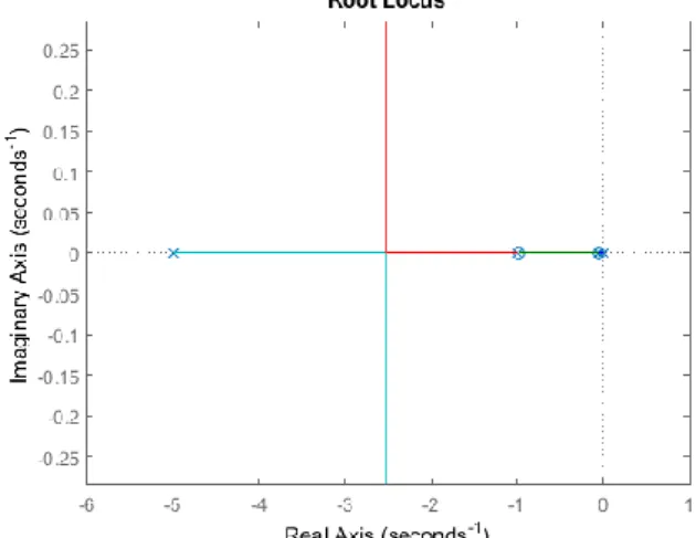
To analyse the system stability of the time domain, root locus analysis is the way for checking the stability [18]. Figure (5) shows the root locus analysis for the cruise control system with PID controller. It is obvious that all the poles are lying in the left side of the s-plane, which means that the system is stable.
Figure (5): Root Locus Analysis
7.2. Bode Plot Analysis
To analyse the frequency response of the system, we have to use bode plot analysis [18]. Figure (6) illustrates the frequency response (magnitude and phase plot) of the open loop cruise control system together with the PSO based PID controller.
Figure (6): Magnitude and Phase plot
8. Robustness Analysis
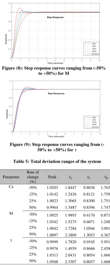
The ability of the controller to tolerate uncertainties existed in some parameters of the system can be evaluated by using the robustness analysis [19]. The PID controller that is designed for the cruise control system is tested with the presence of some parameters uncertainties. The uncertainties of the cruise control system model are specified in terms of variations in the aerodynamic drag, mass, and time delay constants ( , , and respectively). These constants are deviated in a range of of their nominal values with a step size of . Figures (7) through (9) show the step responses of the PID controlled cruise control system with , , and constants variations around their nominal responses respectively.
Figures (7) through (9) give the impression that the deviation of the response curves (±50% and ±25%) for the selected parameters around their nominal response is small. In addition, this analysis can ensure the capability of the PID controller to maintain the stability of the cruise control system and to perform well in spite of the large variation. Table (4) and (5) list a summary of the results of PID robustness analysis and show the total deviation ranges of the system respectively.
Table (4): Robustness analysis results of the PID based cruise control system
Parameter peak settling time rise time peak time Ca 0.0239 0.6021 0.0360 0.0166 M 0.0883 0.6533 0.8878 3.4968 Τ 0.0593 0.8368 0.1491 4.2851 Average 0.0571 0.6974 0.3576 2.5995
Figure (7): Step response curves ranging from (-50% to +50%) for 𝑪𝒂
Figure (8): Step response curves ranging from (-50% to +50%) for M
Figure (9): Step response curves ranging from (-50% to+50%) for
Table 5: Total deviation ranges of the system
Parameter Rate of change (%) Peak Ca -50% 1.0203 1.8447 0.8036 1.7638 -25% 1.0142 1.2426 0.8121 1.7596 25% 1.0023 1.3065 0.8300 1.7513 50% 0.9964 1.3487 0.8396 1.7472 M -50% 1.0925 1.9893 0.4176 0.8711 -25% 1.0342 1.5275 0.6071 1.2408 25% 1.0042 1.7284 1.0566 3.0916 50% 1.0097 2.1809 1.3053 4.3678 τ -50% 0.9999 1.7820 0.9545 5.9512 -25% 0.9976 1.4939 0.8666 2.4588 25% 1.0313 2.0431 0.8054 1.6662 50% 1.0568 2.3307 0.8057 1.6685
From table (5), the average of deviation of maximum overshoot, settling time, rise time and peak time are 0.0571, 0.6973, 0.3576 and 2.5994 respectively. It can be figured out that the ranges of total deviation are within the limits and are acceptable. In accordance to the previous results, the cruise control system with PSO based PID controller
8.
Conclusion
In this study, a PID controller using PSO algorithm has been proposed to undertake the controlling of cruise control system. A comparison based on the system performance has been done among the PSO based PID controller, conventional PID, fuzzy logic controller, state space controller, and Genetic algorithm based PID controller. The result of the comparison shows that there is a great improvement in the response over other controllers in terms of settling time, rise time, peak time, and maximum overshot. Finally, the uncertainty test analysis shows a robust behavior of the PID based cruise control system in terms of the variation of some system parameters.
References
[1] N. Vedam, I. Diaz-Rodriguez, and S. P. Bhattacharyya, “A novel approach to the design of controllers in an automotive cruise-control system,” in IECON 2014 - 40th Annual Conference of the IEEE Industrial Electronics Society, 2014, pp. 2927–2932.
[2] D. Kim, S. Moon, J. Park, H. J. Kim, and K. Yi, “Design of an Adaptive Cruise Control / Collision Avoidance with lane change support
for vehicle autonomous driving,” in 2009
ICCAS-SICE, 2009, pp. 2938–2943.
[3] A. O‟Dwyer, “PI and PID controller tuning rules: an overview and personal perspective,” in 2006 IET Irish Signals and Systems Conference, 2006, pp. 161–166.
[4] A. Elgammal and A. El-Samahy, “A modified design of PID controller for DC motor drives using Particle Swarm Optimization PSO.” pp. 419–424, 2009.
[5] K. Sailan and K. D. Kuhnert, “M ODELING A ND D ESIGN OF C RUISE CONTROL S YSTEM W ITH F EEDFORWARD,” pp. 339– 349, 2013.
[6] K. Osman, M. F. Rahmat, and M. A. Ahmad, “Modelling and controller design for a cruise control system,” in 2009 5th International Colloquium on Signal Processing Its Applications, 2009, pp. 254–258.
[7] M. K. Rout, D. Sain, S. K. Swain, and S. K. Mishra, “PID controller design for cruise control system using genetic algorithm,” in
2016 International Conference on Electrical, Electronics, and Optimization Techniques (ICEEOT), 2016, pp. 4170–4174.
Intelligent Vehicles `92 Symposium, 1992, pp. 173–178.
[9] M. (Website of the U. of C and 1997.)
Michigan, “Control Tutorial for Matlab,”
1997. [Online]. Available:
http://www.engin.umich.edu/group/ctm/exa mples/cruise/ccSS.html.
[10] K. Osman, M. F. Rahmat, and M. A.
Ahmad, “Modelling and Controller Design for a Cruise Control System,” no. 1, pp. 254–258, 2009.
[11] A. O. Dwyer, “PI and PID controller tuning
rules : an overview and personal perspective GC ,( s ) = K,” pp. 161–166, 2006.
[12] Y. Shi and R. C. Eberhart, “Empirical study
of particle swarm optimization,” in
Proceedings of the 1999 Congress on Evolutionary Computation-CEC99 (Cat. No. 99TH8406), 1999, vol. 3, p. 1950 Vol. 3.
[13] J. Kennedy and R. Eberhart, “Particle swarm
optimization,” Neural Networks, 1995.
Proceedings., IEEE Int. Conf., vol. 4, pp. 1942–1948 vol.4, 1995.
[14] Eberhart and Y. Shi, “Particle swarm
optimization: developments, applications and resources,” in Proceedings of the 2001 Congress on Evolutionary Computation (IEEE Cat. No.01TH8546), 2001, vol. 1, pp.
81–86 vol. 1.
[15] Y. Shi and R. C. Eberhart, “Parameter
selection in particle swarm optimization,” in
Evolutionary Programming VII: 7th International Conference, EP98 San Diego, California, USA, March 25--27, 1998 Proceedings, V. W. Porto, N. Saravanan, D. Waagen, and A. E. Eiben, Eds. Berlin, Heidelberg: Springer Berlin Heidelberg, 1998, pp. 591–600.
[16] X.-S. Yang, Ed., “Nature-Inspired
Optimization Algorithms,” in
Nature-Inspired Optimization Algorithms, Oxford: Elsevier, 2014, p. iii-.
[17] M. A. Sahib and B. S. Ahmed, “A new
multiobjective performance criterion used in {PID} tuning optimization algorithms,” J. Adv. Res., vol. 7, no. 1, pp. 125–134, 2016.
[18] K. Ogata, Modern Control Engineering 4Th
Ed. Prentice-Hall Of India Pvt. Limited, 2002.
[19] M. A. Sahib, “A novel optimal PID plus second order derivative controller for AVR system,” Eng. Sci. Technol. an Int. J., vol. 18, no. 2, pp. 194–206, 2015.