J
ÜRGENJ
UNGM
APPING OF
B
USINESS
P
ROCESS
M
ODELS TO
W
ORKFLOW
S
CHEMATA
–
A
N
E
XAMPLE
U
SING
MEMO-O
RG
ML
AND
XPDL
April 2004
J
ÜRGENJ
UNGM
APPING OF
B
USINESS
P
ROCESS
M
ODELS TO
W
ORKFLOW
S
CHEMATA
–
A
N
E
XAMPLE
U
SING
MEMO-O
RG
ML
AND
XPDL
April 2004
Die Arbeitsberichte des Instituts für Wirtschaftsinformatik dienen der Darstellung vorläufiger Ergebnisse, die i.d.R. noch für spätere Veröffentlichungen überarbeitet werden. Die Autoren sind deshalb für kritische Hinweise dankbar.
All rights reserved. No part of this report may be reproduced by any means, or translated.
Arbeitsberichte des Instituts für Wirtschaftsinformatik
Herausgegeben von / Edited by: Prof. Dr. Ulrich Frank
Prof. Dr. J. Felix Hampe Prof. Dr. Klaus G. Troitzsch
Bezugsquelle / Source of Supply: Institut für Wirtschafts- und Verwaltungsinformatik Universität Koblenz-Landau Universitätsstraße 1 56070 Koblenz Tel.: 0261-287-2520 Fax: 0261-287-2521 Email: [email protected] WWW: http://www.uni-koblenz.de/~iwi Anschrift der Verfasser
Address of the authors: Dipl. Inform. Jürgen Jung Institut für Wirtschafts- und Verwaltungsinformatik Universität Koblenz-Landau Universitätsstraße 1
D-56070 Koblenz
The "Arbeitsberichte des Instituts für Wirtschaftsinformatik" comprise preliminary results which will usually be revised for subsequent publications. Critical comments would be appreciated by the authors.
Alle Rechte vorbehalten. Insbesondere die der Übersetzung, des Nachdruckes, des Vortrags, der Entnahme von Abbildungen und Tabellen - auch bei nur auszugsweiser Verwertung.
Contents
Contents... 4
List of Figures ... 6
1 Introduction ... 7
2 Business Process Modelling... 7
2.1 General Overview ... 8
2.2 Business Process Modelling with MEMO-OrgML... 8
2.2.1 Processes ... 9
2.2.2 Events ... 11
2.2.3 Control Flow ... 12
2.2.4 Additional Concepts... 13
2.3 Other Business Modelling Concepts ... 14
2.3.1 Organisational Units... 14
2.3.2 General Resources... 15
3 Workflow Modelling... 17
3.1 General Overview ... 17
3.1.1 Workflow Management Coalition... 17
3.1.2 Workflow Specification Languages ... 19
3.2 Basic workflow concepts ... 20
3.2.1 Workflow Process Definition... 21
3.2.2 Workflow Process Activities... 21
3.2.3 Transitions... 23
3.3 Extended Concepts... 23
3.3.1 Workflow Participants... 23
3.3.2 Workflow Application Declaration... 24
4 Mapping OrgML to XPDL... 24
4.1 Workflow Process Definitions ... 24
4.1.1 Workflow Process Definition Header ... 25
4.1.2 Workflow Process Redefinable Header. ... 26
4.1.3 Generation of Headers... 26
4.2 Resources, Information and Organisational Units ... 26
4.2.1 Human Resources... 26 4.2.2 Software ... 27 4.2.3 Information... 28 4.3 Processes ... 28 4.3.1 Manual Processes ... 29 4.3.2 Semi-Automated Processes ... 31 4.3.3 Automatic Process... 31 4.3.4 Aggregated Process ... 31
4.4 Control Flow and Events... 32
4.5 Data ... 32
5 Prototypical Tool-Support... 32
5.1 Implementation of MEMO-OrgML using MetaEdit+ ... 33
5.1.1 Process Decomposition Diagrams... 33
5.1.2 Process Model Diagrams... 35
5.2 Extending Business Process Models with Workflow-specific information... 36
5.2.1 Workflow Specification Diagram ... 36
5.2.2 Workflow Activity Specification Diagram ... 37
5.2.3 Summary of Business- and Workflow-Diagrams ... 38
5.3.1 Workflow Process Specification Headers and Packages ... 40
5.3.2 Workflow-Specification ... 41
5.3.3 Activities ... 41
5.3.4 Transitions... 42
5.4 Configuration of the WfMS ... 43
5.4.1 Mapping of Participants to users... 43
5.4.2 Updating Workflow-Data... 44
5.4.3 Mapping of Workflow-Applications to Procedures/Applications ... 44
5.4.4 Example-Implementation of Prototypical Workflow-Applications... 44
6 Summary and Future Work ... 47
7 Acknowledgments... 47
Abbreviations ... 48
References ... 49
List of Figures
Figure 1: Process Modelled Using MEMO-OrgML ... 9
Figure 2: Process ... 9
Figure 3: Types of Processes... 10
Figure 4: Continuously Running Process... 10
Figure 5: Aggregated Process ... 11
Figure 6: External Processes ... 11
Figure 7: General Events... 11
Figure 8: Time-related Events... 12
Figure 9: Example for a Sequence ... 12
Figure 10: Alternative Execution ... 13
Figure 11: Parallel execution... 13
Figure 12: Additional Concepts ... 14
Figure 13: Specification and example of organisational units ... 15
Figure 14: Excerpt from the resources' meta-model ... 16
Figure 15: Workflow Reference Model of the WfMC... 18
Figure 16: Meta-model of the WfMC ... 20
Figure 17: Different kinds of Activities in XPDL... 21
Figure 18: Prefix of a Workflow Process Definition ... 25
Figure 19: Attributes of a Workflow Process Definition Header... 25
Figure 20: Attributes of a Workflow Process Redefinable Header... 26
Figure 21: Correlation between Human Resources and Participants... 27
Figure 22: Correlation between Software and Application... 27
Figure 23: Correlation between Information and Data ... 28
Figure 24: Example for manual processes ... 29
Figure 25: Example for alternative 1... 29
Figure 26: Mapping of manual processes ... 30
Figure 27: Attributes of a manual activity ... 31
Figure 28: Attributes of a semi-automated activity... 31
Figure 29: Attributes of a automatic activity ... 31
Figure 30: Transitions ... 32
Figure 31: Mapping of data... 32
Figure 32: Example Process Decomposition Diagram as realised in MetaEdit+ ... 34
Figure 33: Example Process Model Diagram ... 35
Figure 34: Example Workflow-Specification-Diagram... 37
Figure 35: Example Workflow-Activity-Specification... 38
Figure 36: Structure of Diagram and Object Types ... 38
Figure 37: Decomposition of Workflow-Process 0... 39
Figure 38: Process-Model of Workflow-Process 0 ... 39
Figure 39: Mapping of processes to activities... 42
Figure 40: Example Containing a Parallel Join and Split ... 43
Figure 41: Extended Attributes of the Shark-Engine ... 44
Figure 42: XPDL-specification of the e-mail-sender... 45
Figure 43: Implementation of an E-Mail-Notification... 46
Figure 44: Mapping of actual parameters to an application... 46
1 Introduction
Business process modelling (BPM) and Workflow Management (WfM) are two popular subjects in the area of information systems research (IS research). On the one hand they both seem to be very similar but on the other hand they concern the same subject from two different points of view. BPM and WfM foster a mainly process-oriented perspective on organisations. This process-oriented view comprises activities and their relationships within and to an organisation’s context. Relationships among business processes might be specified using control flow (consecutive, parallel or alternative execution), hierarchical decomposition and/or generic relationships. Relationships to the organisational context comprise the assignment of organisational units (company, department, role) and resources (tools, machinery).
Nevertheless, a more differentiating reflection on business processes and workflows seems to be appropriate1. Referring to several sources, they both represent different levels of abstraction on process-oriented organisations. According to Frank and van Laak a workflow mainly concentrates on the processing of digital office documents2. Human activities (in terms of manual processes) as well as decision making processes are left out or at least reduced to interactions with software applications. Similar discussions on conceptual distinctions can be found in the literature. Some examples are given as follows: Böhm summarises the conceptual differences between business processes and workflows as the emphasis of IT on workflows. Like other authors, he places business processes more on a conceptual level of the enterprise3.
Junginger also mentions the fact that every kind of resource might be assigned to a business process4 while workflows are mainly supported by IT-related resources. Stark characterises workflow by the management and support of business processes combined with IT5.
This research paper describes a first approach towards the mapping of concepts of a given business-process-modelling-language to workflow schemata. This work outlines conceptual equivalences and differences. For the support of the mapping of business processes to workflow schemata we will especially focus on information which has to be added to business processes in order to map them to workflows. The structure of this report is given as follows: The next two sections give an overview on business process modelling (section 2) and workflow management (section 3), respectively. Extensions to the business process modelling language (section 4) as well as a prototypical implementation of a tool (section 5) will be presented afterwards. This report ends with a summary, concluding remark and an outlook to future work in section 6.
2 Business Process Modelling
This preliminary section provides an overview over general aspects and the area of application of business process modelling. Additionally, core concepts of a business process language will be presented.
1 The notion of business process and workflow are further presented in the following sections 2 and 3. 2 Cf. [FrLa03]
3 Cf. [Böhm00, p. 3] 4 Cf. [Jung01, p. 18]
5 “Workflow promises a new solution to an age-old problem: managing and supporting business processes. What is new about workflow is the way it harnesses the power of information technology to structured work.” [Sta97, p. 5]
2.1 General Overview
The analysis, representation and management of knowledge about an organisation and its processes has always been very important6. A lot of work has been done on the development and evaluation of ontologies for process modelling7, the specification of process modelling languages8 as well as on business process modelling methods and concepts9. Business process models can be used for different kinds of purposes:
• Documentation of processes of an organisation to foster communication10
• Analysis of business processes11
• Simulation of processes12
• Support for business process re-engineering13
• Software development of process-oriented applications14
The documentation of an organisation’s processes (as well as other organisational aspects like its structure or strategy) fosters communication with new employees or external consultants. Business process models represent a common medium for the communication of domain experts and novices. They offer domain level concepts and enable a broader distribution of knowledge among other business-related people with different skills and knowledge of an organisation.
The analysis of business processes relies on a detailed description (with respect to the analysis’ purpose) of process models and related concepts. Depending on the analysis’ purpose, a modelling language has to offer language features for the modelling of the facts which are in its scope. Analysis might for example support the detection of weaknesses in existing processes. Appropriate language features provided by a process modelling language support the determination of media clashes, unnecessary processes or potentials for further optimisations. Nevertheless, the potential for further optimisations relies on the degree of formal description of the business process model. Depending on identified weaknesses, a business process re-engineering might be applicable.
2.2 Business Process Modelling with MEMO-OrgML
Multi-Perspective Enterprise Modelling (MEMO) is a method for the modelling of organisations according to different views as well as different levels of abstraction15. MEMO has been initiated by Ulrich Frank and is the main research topic of the research group ’Enterprise Modelling’ at the University of Koblenz. MEMO includes several languages for modelling static, functional and dynamic aspects of an enterprise. One of these languages is the MEMO-OrgML (Organisation Modelling Language), which supports modelling of organisational structures and processes. Resource modelling has not been subject of the first conceptualisation of the MEMO-OrgML but will be added shortly16.
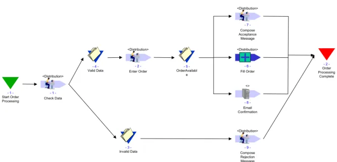
An introductory example for a process that has been modelled using MEMO-OrgML is given in Figure 1. An order is received by the distribution department and the data will be checked directly afterwards (process No. 1 called ’Check Data’). The order will be further processed if the given data is
6 Cf. [KoPl00]
7 Cf. [WaWe93], [Web97] and [GrRo99]. 8 Cf. [EJLT99] and [SuOs97]
9 Cf. [Herb97] and [Öst95]. 10 Cf. [Obe96] and [Fra99]
11 Cf. [BeJo01], [EJLT99] and [Sche99]. 12 Cf. [Baum96]
13 Cf. [CKO92] and [Obe96] 14 Cf. [CKO92], [Öst95] and [Fra99] 15 Cf. for example [Fra99].
valid (event No. 4 called ‘Valid Data’) or aborted if the data seems to be invalid (event No. 3). Aborting an order results in sending a rejection message to the customer in process No. 9 (‘Compose Rejection Message’). Further processing of the order comprises the entering of the data into the order-management-system (process No. 2: ‘Enter Order’) the parallel execution of the processes 6, 7 and 8. Process No. 6 is a composed process which consists of one or more sub processes. The process called ‘Compose Acceptance Message’ (No. 7) is a semi-automated process executed by the distribution department. Process No. 8 is a fully automated process sending a default email-message to the customer. 1 -Start Order Processing <Distribution> Check Data 1 2 -Order Processing Complete <Distribution> Compose Rejection Message 9 3 -Invalid Data 4 -Valid Data <Distribution> Enter Order - 2 - 5 -OrderAvailabl e <Distribution> Fill Order 6 -<Distribution> Compose Acceptance Message 7 -<> Email Confirmation 8
-Figure 1: Process Modelled Using MEMO-OrgML
The example given above contains only an extract of the language features offered by the MEMO-OrgML. A detailed presentation of all language features will be given in the following sections. Section 2.2.1 starts with different kinds of processes and will be followed by the presentation of events in section 2.2.2 and the specification of control-flow between process elements in section 2.2.3. We will close with the discussion of additional concepts provided by the MEMO-OrgML in section 2.2.4.
2.2.1 Processes
The general specification of a process in MEMO-OrgML is shown in Figure 2. Every process can be assigned to an organisational unit, which is annotated on top of the graphical notation of a process. Examples for organisational units are a whole organisation, department, business unit or a role. Additionally, a process can be identified by a unique number (‘number’ in Figure 2) and described by a meaningful qualifier.
<role or organisation>
qualifier
number
There are several different types of processes in MEMO-OrgML which are classified using different kinds of aspects.
2.2.1.1
Elementary Process Types
Elementary processes in MEMO-OrgML are classified by the types of resources required for their execution. Processes can be executed manually, automatically or semi-automated (refer to the graphical notation in Figure 3). Manual processes are exclusively performed by human resources without any IT-support. In contrast to this, automated resources are solely executed by computing machinery without any support of human resources. Semi-automated processes refer to a support by human and technological resources. Whether semi or fully automated, the focus is on IT resources.
<role or organisation> qualifier number -<role or organisation> qualifier number -<role or organisation> qualifier number
-Figure 3: Types of Processes
The processes presented so far are usually subject to a specific start and end. A manual process for the installation of a controller for a central heating in a building can only begin after an order is entered and will end with the completion of the order. Nevertheless, there are some tasks without a specific start and end. Those processes usually run continuously. An example for such a process is the quality assurance. Tasks related to quality assurance might not directly relate to specific sub processes in software development. Furthermore, quality assurance is orthogonal to a software development method because it has to be guaranteed at every stage of a software development process. Hence, quality assurance has to be done continuously, keeping every task regarding software-development in mind. The graphical notation for continuously running processes is displayed in Figure 4.
<role or organisation>
qualifier
number
-Figure 4: Continuously Running Process
2.2.1.2
Aggregated Process Type
An aggregated process is composed of other elementary or aggregated processes. Equally like general processes, aggregated processes can be specified by assigning an organisational unit and annotating a unique number and a descriptive name (qualifier). The graphical notation for an aggregated process is given in Figure 5. It is important to note that an aggregated process is mainly specified by its sub processes. Also its sub processes are assigned to an organisational unit and specified according to necessary resources. Furthermore, an essential part for the specification of an aggregated process is the control flow between its sub processes. Hence, every aggregated process has to be specified by a process model containing its sub processes and their control flow.
<role or organisation>
qualifier
number
-Figure 5: Aggregated Process
2.2.1.3
External Processes
External processes are generally executed by external organisations. Examples for external processes are those which are executed by an autonomous partner or a subcontractor. In MEMO-OrgML, we differentiate between different kinds of partners regarding external processes. The main focus is on the independency of the given organisation. According to the graphical notation given in Figure 6, there are types of partners (from left to right): contractor, autonomous institution and partner.
<role or organisation> qualifier number -<role or organisation> qualifier number -<role or organisation> qualifier number
-Figure 6: External Processes
A contractor is an external organisation, which is bound to the terms and conditions of the given organisation. It is an independent organisation but depends on the requirements given by the principal. An example for a contractor is the supply industry in the automotive sector. Every supplier depends on a car manufacturer specifying the technical data and contracts. In contrast to this, an autonomous institution is very independent from the given organisation. An autonomous organisation is free in the specification of contracts and cannot be forced by other organisations. External partners are a special kind of contractor, which are more independent than a contractor but less free than an autonomous organisation.
2.2.2 Events
Events represent special states during the execution of business processes. An event is a momentous symptom and not a period of time. The most important types of events in MEMO-OrgML are given in Figure 7 (from left to right): Start event, stop event, an event indicating the change of a state and an event for an incoming message. For every business process there is a dedicated starting event as well as a final state. Those events form the boundary between the modelled process and the organisation’s context. In contrast to a general event indicating the change of an internal state, the incoming information event corresponds to an increase of information within the process system.
ID -qualifier ID -qualifier ID -qualifier ID -qualifier
Figure 7: General Events
The event types presented so far cover general aspects of process models like start, stop, status changes and incoming news. Nevertheless, they ignore timely aspects like points of time and periods (their graphical notation is given in Figure 8). A point of time corresponds to a well-defined timestamp and a period to an interval given by a well-defined end. Hence, a
moment can be specified by its absolute specification. The end of a period might only be described by a timestamp relative to a given or imaginary starting point.
ID
-qualifier
ID
-qualifier
Figure 8: Time-related Events
2.2.3 Control Flow
Control flow specifies flow-related relationships between processes. Those relationships might be determined by logical or temporal constraints on the execution of business processes. We mainly distinguish between sequence, concurrency and alternative.
2.2.3.1
Sequence
A sequence in business process modelling usually corresponds to the consecutive execution of processes. Hence, the termination of one process results in the instantiation of exactly one following process. Figure 9 shows an example for a sequential execution regarding to events. The interpretation is as follows: If event No. 1 (data available) occurs, process No. 1
(Check Data) can be started. The termination of this process fires event No. 2.
1 -data available <Distribution> Check Data - 1 - 2 -Data Verified
Figure 9: Example for a Sequence
2.2.3.2
Alternative
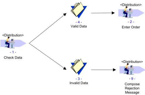
An alternative is as general rule interpreted as a fork of control flow. This means that after the execution of one process called A either a process B or a process C is initiated. Alternative execution of business processes. In other terms there can be only one successor of process A within a concrete instantiation of the whole process, namely B or C in the example. In sense of mathematical logic this represents an exclusive-or (XOR) relationship between following processes. This is not restricted to only two processes. Several succeeding processes can be involved in such a relation. In addition to the fork of process flow there is also an equivalent join. The graphical notation for an alternative is given in Figure 10. After the process No. 1 is completed either the events 3 or 4 will be fired. If event No. 3 (data is invalid) is fired, the execution continuous with process No. 2 (enter order)
<Distribution> Check Data 1 -<Distribution> Compose Rejection Message 9 3 -Invalid Data 4 -Valid Data <Distribution> Enter Order 2
-Figure 10: Alternative Execution
2.2.3.3
Concurrency
Many processes can be executed in parallel or concurrently. Generally speaking, the parallel execution is identical with the execution at the same time. In contrast to this, concurrency only means, that processes might be executed independently from others. But there is no such differentiation in MEMO-OrgML. There is only one language feature for concurrency, neglecting the fact of simultaneous execution. An example for the concurrent execution of processes is given in Figure 11. Event No. 5 (OrderAvailable) fires the concurrent execution of the two processes Fill Order and Email Confirmation (AND-split). The synchronisation (AND-join) of these two parallel paths results in event No. 2 called Order Processing
Complete. Alternatively an OR-join17 is possible if only one parallel branch has to terminate
in order to fire event No. 2.
2 -Order Processing Complete <Distribution> Fill Order 6 -<> Email Confirmation 8 5 -OrderAvailabl e
Figure 11: Parallel execution
2.2.4 Additional Concepts
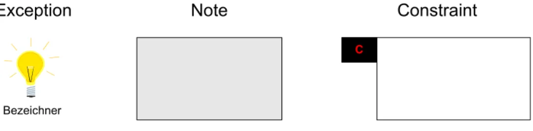
In addition to the process-oriented concepts, exceptions, notes and constraints are provided in the MEMO-OrgML (their corresponding graphical notation is shown in Figure 12). An exception corresponds to an event which indicates an unusual behaviour during the execution
of a process. Examples for such kinds of exception are the failure of an IT resource, the breakdown of a truck or the illness-related absence of a human resource. Those kinds of exception are usually hard to integrate as regular events with business process models using common control flow. It is not always clear what has to be done in case of an exception. Hence, the exception assigned to a business process indicates the appearance of a faulty event. A procedure for handling every kind of exception has to be described or at least a global exception handling routine.
Bezeichner
C
Exception Note Constraint
Figure 12: Additional Concepts
A note is a textual description for special aspects of a business process model and is intended for human readers. Automatic processing of notes by computerised IS-systems is not planned. A given note might be related to a process model, a single model element or any extract from the model. In contrast to this, a constraint serves to the specification of formal conditions. A constraint usually refers to information objects used in the business process. Consequently, a constraint can only be formulated formally if business documents are described in a formal manner.
2.3 Other Business Modelling Concepts
In addition to the process-oriented concepts given in section 2.2 there are two other kinds of language features for modelling process-oriented organisations. Organisational units correspond to departments, divisions or roles which are assigned to a business process as a responsible actor. Resources are actors or tools which are required for the execution of a business process.
2.3.1 Organisational Units
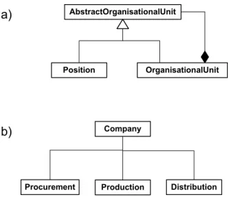
The static structure of organisations can be described by an organisational chart. Such a chart shows an organisation by its sub-units and their respective relationships. The meta-model for the modelling of organisational charts is given in Figure 13 a). An abstract organisation unit might either be a position or an organisational unit. Every organisational unit is a composition of other abstract organisational units. A position is an elementary description of the responsibilities of an employee. An example for an organisational chart is given in Figure 13 b): An imaginary company consists of three departments for procurement, production and distribution.
AbstractOrganisationalUnit
Position OrganisationalUnit a)
b) Company
Procurement Production Distribution
Figure 13: Specification and example of organisational units
Organisational units and roles are elements assigned to business processes and refer to human actors which are responsible for the execution of a business process. Organisational units and positions as described here can be assigned to business processes as described in section 2.2.1. Roles are not necessarily defined in an organisational chart but can be assigned to business processes.
2.3.2 General Resources
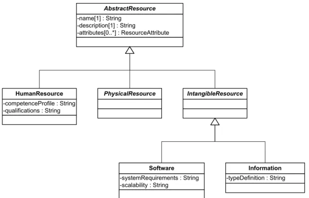
Resources are essential for modelling processes18. Processes and their relationships mainly describe dynamic aspects and the order of events. Resources assigned to processes additionally specify subjects and objects of business processes. Resources are usually not available in an unlimited amount19. Hence, the usage of scarce resources has to be taken into account for the analysis or simulation of processes as well as for the development of a workflow application or an information system. As the resource-modelling-language for MEMO-OrgML is currently under development, no graphical notation will be given here but a short introduction into the underlying meta-model. An excerpt from this meta-model is shown in Figure 14. The class AbstractResource is the root of the generalisation hierarchy on resources. Every resource has a name (name : String), a textual description (description :
String) and a list of resource attributes (attributes[0..*]:ResourceAttribute). Every resource
attribute is a name-type pair for the specification of user-defined attributes on resources.
18 cf. [PSO99]
-name[1] : String -description[1] : String -attributes[0..*] : ResourceAttribute AbstractResource -competenceProfile : String -qualifications : String
HumanResource PhysicalResource IntangibleResource
-systemRequirements : String -scalability : String
Software
-typeDefinition : String
Information
Figure 14: Excerpt from the resources' meta-model
Within the context of workflow-modelling, we generally distinguish between human, physical and intangible resources. A human resource is an abstraction on different perspectives on staff. Examples for such perspectives are concrete employees, roles filled by employees or business-oriented functions. Physical resources comprise all tangible objects used within a business process. Examples for physical resources are production plants, raw material or computer hardware. In contrast to this, intangible resources do not have a physical manifestation. Examples for intangible resources are data, information, software or even knowledge.
Human resources are an abstraction on persons, employees, roles or other staff-related perspectives. They might be associated with concrete persons or employees of an organisation as well as abstract organisational units in an organisational chart. Hence, a human resource can be characterised by different aspects. A human resource …
• … can play an active role
• … may be responsible for the execution of e-business processes
• … needs some qualification and competences for its job
The type HumanResource is a subtype of AbstractResource and has the two attributes
qualification and competenceProfile, both of type String (cf. Figure 14). The qualification
is an objectively describable criterion for the capabilities of a human resource. Usually, the qualification certificate is issued by an established educational body. The competence of a human resource reflects personal skill of human beings. Hence, a competence profile corresponds to personal strengths.
Physical resources comprise all tangible objects used within a business process and are neither human nor intangible. According to Heinen20 - in the context of industrial production - it can be differentiated between non-consumable resources (German: Potentialfaktoren) and consumable resources (Repetierfaktoren). Non-consumable resources are not used up during a manufacturing process and are still available afterwards whereas consumable resources are either becoming a part of the resulting product or are being used up and therefore are not
available anymore21. In the paper at hand we abstract from physical resources, because these are not relevant in our context of workflow applications and the perspectives we present on it. Intangible resources are resources without a physical manifestation. Software in terms of a set of programs that run on a computer hardware is a key resource in the process of supporting workflows. The meta-type Software has two attributes: systemRequirements and
scalability both of type String. The system requirements are modelled as text and describe
the environment for the execution of a software system (i.e. processor architecture, minimum main memory or operating system). Scalability corresponds to the ability of supporting growing numbers of clients. The meta-type Information was created to represent information or knowledge that is relevant within workflows. It has attributes name (a symbolic reference to an information instance) and typeDefinition of type String which describes how the information is structured. Examples for information are certain customer data or enterprise knowledge of some kind.
3 Workflow Modelling
This section provides an overview on workflow management concepts. It covers the basic terminology, major standards for workflow schema interchange and presents a standard for schema definition of the WfMC – XPDL.
3.1 General Overview
Workflow management is an important technology in the area of IS Research and focuses on the support and management of electronically supported processes. This section provides a short introduction into workflow management by giving an overview on common terminology and the description of the standards of the Workflow Management Coalition.
3.1.1 Workflow Management Coalition
The Workflow Management Coalition (WfMC) was founded in 1993 and is an alliance of
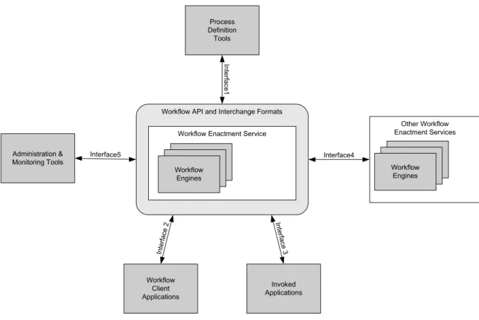
companies and organisations dealing with workflow management. The mission of the WfMC is the foundation of a common terminology regarding workflow management and the establishment of standardised interfaces. These interfaces comprise the definition, execution and management of workflows as well as references to external documents and applications22. The conceptualisation of the interfaces is given by the WfMC’s reference model depicted in Figure 15. Core of the reference model23 are the workflow enactment services using one or more workflow engines for the execution of workflows. A workflow engine is a software managing workflows regarding to given workflow definitions.
21 see [SS01], pp. 89-90
22 Cf. [Jung01, pp. 126] and the references given there 23 The WfMC reference model is specified in [Holl95].
Workflow Client Applications Other Workflow Enactment Services Workflow Engines Workflow API and Interchange Formats
Workflow Enactment Service
Workflow Engines Interface4 Administration & Monitoring Tools Process Definition Tools Invoked Applications In te rfac e1 Interface5 Inte rfac e 2 Interfa ce 3
Figure 15: Workflow Reference Model of the WfMC24
The five different interface definitions correspond to the integration of external aspects:
- Interface 1 specifies the exchange of workflow models between external modelling
tools and a workflow management system. External tools might be graphical editors for workflow definition or just a textual editor. Nevertheless, some general purpose process modelling tools supporting the WfMC standard can be used for the specification of workflows25.
- Interface 2 describes the communication between a WfMS and workflow client
applications. Workflow client applications are applications directly correlated with the workflow engine. They usually implement basic functionality of workflow applications like notification and data transfer26.
- Interface 3 addresses the need of integration of external applications. Usually, the
needed functionality might not be completed by the WfMS. Hence, there has to be an interface to other applications already running in the enterprise27. Examples for such
kind of applications are business related software and special software tools.
- Interface 4: Goal of interface 4 is the integration of other workflow management
systems. The specification comprises the invocation of remote activities, data transfer as well as synchronisation aspects between different workflow enactment services28.
- Interface 5 describes the communication between the workflow enactment services
and external monitoring and administration tools29.
Interface 1 is the most relevant specification for the purpose of mapping business process models to workflows. It concentrates on the specification of different types of workflows
24 Source: [Holl95, p. 20] 25 Cf. [Gad01, p. 48] 26 Cf. [Holl95, pp. 31] 27 Cf. [Holl95, pp. 35]
28 Cf. [Jung01, p. 126] and [Holl95, pp. 41] 29 Cf. [Jung01, p. 126].
(processes) as well as associated organisational units and applications. The system-specific integration of applications is done using interface 2/330.
3.1.2 Workflow Specification Languages
WPDL31 is the first attempt of the WfMC to specify of a standard for the interchange of workflow definitions. Being a standard for exchanging models, it does not comprise a graphical notation. Meanwhile, WPDL has been replaced by XPDL32, an XML-based document definition for workflows. The basic conceptualisation of the XPDL is represented by the meta-model shown in Figure 16. This meta-model generally comprises static entities (e.g. data or applications) as well as dynamic concepts (processes). Static entities are represented by the meta-types
- Workflow Relevant Data,
- Workflow Participant Specification and
- Workflow Application Declaration.
Workflow-relevant data is initialised, created, read from external applications and used during the execution of workflows33. It might be produced by an activity within a workflow or extracted from an external data source (like an enterprise information system). The creation of a new data entity or the digitalisation of a document might be sources for the creation of data in the context of a workflow. Examples for external data sources are corporate databases containing relevant data for an enterprise. These data sources are represented by the meta-type
System and Environmental Data in Figure 16. The workflow participant specification
describes the resources which perform the given workflow processes34. This specification does not necessarily correspond to a human or a single person. It actually represents an abstract resource or a role which can be filled by one or more humans as well as an automated machine. Nevertheless, the specification of a workflow participant corresponds to a resource available in an organisation or an entity in an organisational chart (Resource Repository or
Organisational Model). The workflow application declaration provides the description of
software applications needed for the execution of a workflow process35. Those applications are usually invoked by the workflow engine and workflow-relevant data has to be passed as a parameter. Examples for workflow applications are internal applications as well as external applications like corporate information systems or common office applications. Internal applications are usually provided as part of a workflow management system or can be developed using a proprietary36 development environment or language.
30 Interfaces 2 and 3 are combined to one interface definition by now (cf. [WfMC98] and [Jung01, p. 127]). 31 Workflow Process Definition Language
32 XML Process Definition Language (cf. [Nori02]) 33 Cf. [Nori02, p. 10].
34 Cf. [Nori02, p. 9]. 35 Cf. [Nori02, pp. 9 ].
Workflow Process Definition System and Environmental Data Workflow Relevant Data Workflow Participant Specification Resource Repository or Organizational Model Workflow Application Declaration Activity Set Workflow Process Activity Transition Information Block Activity Sub-Process Definition Atomic Activity 1 * 1 * 1 * 1 * invoke performed by from to 1 * 1 * 1 * 1 *
Figure 16: Meta-model of the WfMC37
A workflow process definition is an aggregation of static entities (data, applications, participants) as well as the description of the system’s dynamic behaviour. Dynamic aspects of the meta-model are represented by the entity-types Transition Information as well as
Workflow Process Activity and its concrete subtypes
- Block Activity,
- Atomic Activity and
- Sub-Process Definition.
An activity is a given unit of work which will be executed by a participant using computer applications38 and relevant data. Additionally, every activity is characterised by a start- and end-time as well as the fact whether it can be executed automatically by the WfMS or by a workflow participant. The transition information specifies the control flow between activities39. It consists of a starting activity, an end-activity and a condition under which the transition is made. An atomic activity is an indivisible unit of work which has to be done at one go. A sub-process definition allows the embedding of another workflow process definition. A block activity consists of a set of other activities (type Activity Set). The semantics of an activity set is similar to the one of a macro. If an activity set is called during the execution of a workflow process, the activities contained in the set are copied into the calling process definition40.
The concepts given here will be further discussed later in this research report. Different types of processes and transitions will be presented in the following section 3.2. Additional concepts like applications or participants are subject to section 3.3.
3.2 Basic workflow concepts
Main concepts for the description of the dynamic aspects of a workflow system are activities and transitions. Activities correspond to defined units of work which can be atomic or consist of a set of activities. The control flow between activities is specified by transitions. Hence, a transition relation between two activities defines the ordering of these activities. An activity can be started if its preceding activities (connected by transitions) have been terminated. Transitions, activities and static entities (i.e. IT-related resources) are grouped by a so called workflow process definitions.
37 Source: [Nori02, p. 12]
38 Cf. [Nori02, p. 8] 39 Cf. [Nori02, p. 9] 40 Cf. [Mato03, p. 13]
3.2.1 Workflow Process Definition
A workflow process definition groups all elements necessary for the execution of a workflow. As shown in the meta-model in Figure 16 these elements comprise dynamic (activities and transitions) and static aspects (data, applications and participants). Additional attributes are a unique identifier, a name and two headers. The process header comprises the creation date, a textual description and different time-related properties (e.g. estimated duration of a process’ execution) of a workflow process. The redefinable header consists of information about the author of the process definition, a country key, its publication status, responsible participants and a version number.
An activity set is a set of activities and transitions. All transitions contained in this set can only start from activities within this set and end in activities within this set. In other words, there are no transitions leaving an activity set or coming from outside. Properties of an activity set are a list of activities, a list of transitions and a unique identifier.
3.2.2 Workflow Process Activities
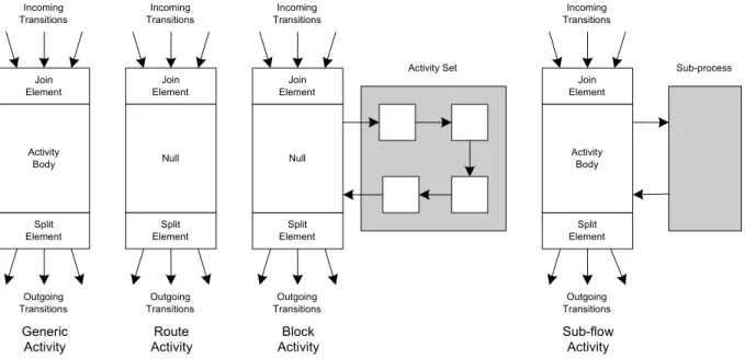
As shown in Figure 16, there are different types of activities within a workflow process definition. An atomic activity is an indivisible unit of work executed under the control of a WfMS. Such an activity can be executed automatically or by a human participant and usually works on workflow-relevant data. In contrast to this, block and route activities do not refer to workflow-relevant data. A block activity executes an activity set and has no own behaviour. Invoking an activity set means the start of the first activity in the set. The execution terminates with the last activity in the activity set (cf. Figure 17). A route activity is an activity with no behaviour. It only serves as a dummy activity for cascading transition conditions41.
Figure 17: Different kinds of Activities in XPDL42
According to XPDL there is only one general XML-element for activities called ‘Activity’. Specific elements for route, block or sub-flow activities are missing. The differentiation between different types of activities is done by the annotation of alternative attributes. Those attributes are named Route, Implementation43 and BlockActivity. Activities can additionally
be specified according to their level of automation (automatic or manual) as well as their
41 Please refer to section 3.2.3. 42 Source: [Nori02, p.30]
43 The WfMC uses three different names for the same concept: An atomic activity (cf. [Nori02] , p. 12) is also called generic activity (cf. [Nori02], p. 30) and implementation (cf. [Nori02], p. 31).
Join Element Split Element Activity Body Incoming Transitions Outgoing Transitions Generic Activity Join Element Split Element Null Incoming Transitions Outgoing Transitions Block Activity Join Element Split Element Null Incoming Transitions Outgoing Transitions Route Activity Join Element Split Element Activity Body Incoming Transitions Outgoing Transitions Sub-flow Activity Sub-process Activity Set
implementation alternatives (no implementation, tool or subflow). An automatic activity can be fully controlled by the workflow engine using internal and external applications. Manual activities require the involvement of a human being. Activities corresponding to the no-implementation alternative cannot be supported by an WfMS. These are usually manual tasks which can be executed without the support of a WfMS. A tool supported implementation implies the support of a software application. Such applications have to be assigned to this kind of activity44. If the implementation type is set to subflow, the execution has to be delegated to another workflow process definition. Parameters can be passed to such a sub-flow activity and the synchronisation can be specified with respect to a synchronous or asynchronous execution. Synchronous execution requires the calling process to wait for the termination of the called process. After its termination the called process might pass output values to the calling process. During an asynchronous execution the calling process has not to wait for the termination of the called process and output values are not possible.
Atomic, tool-supported activities might be executed by a human actor. Such a human resource corresponds to the XPDL-type participants. Human resources and participants can be associated with staff members45. This association is not part of the XPDL specification and has to be implemented by a concrete WfMS-implementation. XPDL only describes on an abstract level the participants of a workflow correlating them to typical roles. In contrast to this a WfMS manages users of a system which can in turn fill a specific role. The mapping of the roles provided in an XPDL-description to roles given in a WfS46 has to be done by the WfS itself. If an XPDL-participant cannot be mapped to a WfS-role, a default role has to be applied. A participant without any correspondence in the WfMS might – for example – be assigned to a default role like an administrator.
Additional information for activities are deadlines and simulation information. A deadline is the expiration of a given period of time. A deadline might for example be a milestone (given a project management context) or specific appointment. The occurrence of a deadline can be handled synchronously (the current activity is interrupted by the deadline) or asynchronously (the handling of the deadline has to be done parallel to the currently running activity). Simulation information extends the model by giving specific data for the simulation of models. Examples for specific data are average costs, expected duration and average waiting time.
As shown in Figure 17, every activity is a join-point for several incoming transitions (join element) and specifies the type of splitting for outgoing transitions (split element). Both – join and split – can refer to a parallel or an alternative execution of workflows. An alternative split (XOR) represents a fork specifying that exactly one of the given alternatives can be executed. An alternative join corresponds to the synchronisation of an alternative split47. The parallel execution of activities is started by an AND-split and ended by an AND-join. Rules for the construction of workflow descriptions regarding parallel and alternative connectors (splits and joins) are classified by so called conformance classes. A conformance class specifies criteria for the construction of diagrams of activities. A NON-BLOCKED conformance class implies no formal properties of a diagram regarding the relationships between splits and joins. If the conformance class is set to LOOP-BLOCKED, the graph build by the activities and transitions is a directed acyclic graph48. A FULL-BLOCKED graph implies that every AND-split has exactly one AND-join, every XOR-AND-split exactly one XOR-join and vice versa. Additionally every path starting from the split will reach the corresponding join.
44 The assignment of applications to workflows will be presented and further discussed in section 3.3.2. 45 This will be subject to section 3.3.1.
46 Workflow System
47 We assume that every alternative split has an equivalent alternative join. Hence, every path beginning at a given alternative split will end at one – and exactly one – alternative join.
3.2.3 Transitions
A transition is the partly specification of the control flow between activities. As shown in section 3.2.2, the information whether incoming transitions of an activity are disjoint (alternative) or conjoint (parallel) is assigned to the activity. Additional information about a transition is assigned to the so called transition information49. Basic elements of such a transition are its name (i.e. a character string), a textual description and a condition. While a description usually consists of a natural language description a condition should be a (semi-)formal specification of the circumstances enabling or disabling a transition. It therefore has to be represented by a Boolean expression. Additionally, a starting and an ending node are assigned to transition information.
Consequently, every transition is characterised by exactly one source activity (from), exactly one destination activity (to) and a Boolean expression representing a firing condition. There are four different kinds of conditions in XPDL:
- CONDITION: A transition can fire if its condition is evaluated to true.
- OTHERWISE: Indicates a default transition which will fire if no other transition’s condition evaluates to true.
- EXCEPTION: An exception is a special transition indicating an abnormal behaviour. An exception-condition can trigger the rising of a special condition.
- DEFAULTEXCEPTION: A default exception is triggered if all other exception conditions are evaluated to false.
Dis- and conjointness of transitions are specified by the splits and joins assigned to activities. Conditions regarding the validity of the execution of a transition are assigned to the transition information. Hence, the description of the control flow in a workflow model is split up into the nodes (activities) and arcs (transition information) of a workflow model.
3.3 Extended Concepts
Workflows are managed by a workflow management system by assigning tasks (as parts of workflow instances) to given resources. Such a resource might be either a human participant or a workflow application. A human resource usually corresponds to a role filled by a specific person in an organisation. A workflow application might be categorised into internal and external applications. An internal application is usually implemented by the WfMC itself50 and is closely coupled to the workflow system. An external application can be characterised as an application independent from the WfMS.
Regarding the specification of resources for the execution of workflows there is one major problem. On the one hand, XPDL aims to be a language for a system-independent workflow definition interchange. Hence, a workflow model described using the XPDL should be independent from any specific workflow engine. On the other hand, the description given by an XPDL-document should be precise enough for the execution of workflows. This aspect might require the annotation of specific users or applications which are subject to a proprietary definition by a WfMS. Consequently, the XPDL-definition only provides an abstract mechanism for the specification of human resources and software-applications.
3.3.1 Workflow Participants
Regarding the XPDL-specification, workflow participants are “an abstraction level between the real performer and the activity, which has to be performed.”51 The engine has to map
49 “The Transition Information describes possible transitions between activities and the conditions that enable or disable them (the transitions) during workflow execution. Further control and structure restrictions may be expressed in the Activity definition.” [Nori02, p. 40]
50 To be more precise: An internal workflow application is usually implemented using a programming language and environment given by the WfMS.
every abstract participant to a user given in the workflow management system’s environment. Every abstract participant is characterised by its unique name and type52. Possible types of workflow participants are:
- RESOURCE: A specific resource given in a workflow management system’s environment.
- RESOURCE_SET: A set of resources.
- ROLE: A role description that directly corresponds to a role given in an organisational chart. Such a role might be a function or some kind of qualification filled by a human. - ORGANIZATIONAL_UNIT: An arbitrary element of an organisational chart.
- HUMAN: A human being interacting with the WfMS by worklists and/or applications (i.e. a concrete human being, like ‘John Miller’)
- SYSTEM: A software application representing the participant of a fully automated workflow.
Those participants are assigned to activities of a workflow model using the Performer -attribute of an activity53. Hence, an activity keeps a reference to an abstract participant using the performer-attribute (which is rather a character string than a reference to a workflow participant). Unique identifiers of participants are used to specify an activity’s performers. A workflow model describes participants on an abstract level, like organisational units or roles.
3.3.2 Workflow Application Declaration
Regarding to Junginger, workflow applications can be divided into internal and external applications54. An internal workflow application is implemented as part of the WfMS. They are usually implemented using a programming language given by the WfMS. In the context of XPDL, those applications are called procedure. An external application is an individual software package which can be used by a WfMS. Hence, an internal application is part of the WfS and an external applications is part of the corporate information system involved in a workflow.
Using XPDL, a workflow application is specified by a unique identifier, its type and a list of parameters. The name of an application is rather the unique id and does not necessarily correspond to its physical location or a concrete implementation. Like the description of workflow participants, the identification of a workflow application is only a symbolic link. The interpretation of such a symbolic link representing a workflow application depends on the WfMS at hand. There are workflow engines supporting internal applications, external applications or both55. Hence, the differentiation between internal and external workflow
applications relies on the capabilities of the workflow engine. In general, the mapping of abstract applications (procedures or applications) to concrete applications has to be done by the WfMS
4 Mapping OrgML to XPDL
This section focuses on the information given by a business process model and its transformation to a workflow model.
4.1 Workflow Process Definitions
Every workflow process definition in XPDL generally consists of activities, transitions, applications, participants and workflow-relevant data. Hence, such a workflow process
52 Additional attributes are a textual description and a reference to an external description of a participant. 53 Cf. [Nori02, p. 31].
54 Cf. [Jung01]. 55 Cf. [Jung01].
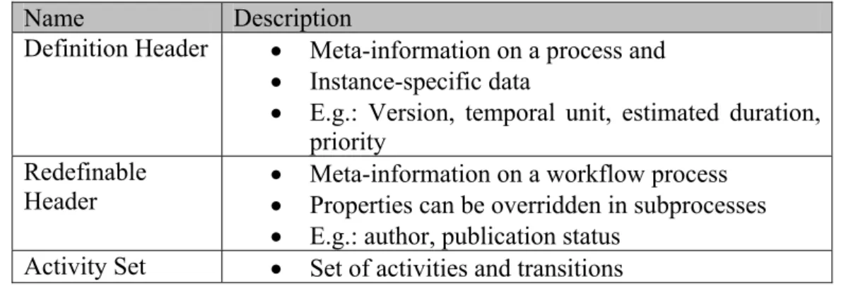
definition comprises its activities and corresponding resources56. Additionally, every workflow process definition consists of two different headers and a body. The two headers are
the definition header and the redefinable header. The workflow process definition header is
valid for all sub-activities and a workflow process redefinable header might be overridden in subflows.
Name Description
Definition Header • Meta-information on a process and
• Instance-specific data
• E.g.: Version, temporal unit, estimated duration, priority
Redefinable
Header •• Meta-information on a workflow process Properties can be overridden in subprocesses
• E.g.: author, publication status Activity Set • Set of activities and transitions
Figure 18: Prefix of a Workflow Process Definition
4.1.1 Workflow Process Definition Header
Attributes of a definition header for workflow processes are listed in Figure 19. The creation date is assigned to a process definition during its definition and therefore represents the definition time of a workflow schema. This information can be extracted from the modelling tool supporting MEMO-OrgML and is not part of the MEMO languages’ specification. The workflow process’ description can be seen as the description of the top-level process of a decomposition hierarchy in MEMO-OrgML. The valid-from- and valid-to-attributes allow the specification of a period of time for the validity of a process definition. Hence, a process definition can only be used between valid from and valid to (empty string means unlimited validity). As here is no equivalent concept in MEMO-OrgML we assume an unlimited validity for all processes.
OrgML (Meta-Data) XPDL:Definition Header Creation Date (meta) Created (creation date)
Process Description Description
Duration & Duration Unit
Limit (vendor-specific) Priority Time Estimation Valid From/To Waiting Time Working Time
Figure 19: Attributes of a Workflow Process Definition Header
The other attributes only contain information on workflow instances. The duration- and limit-attribute (the limit has to be interpreted by a specific WfMS and has no meaning in the context of XPDL) contain an expected duration for the execution of the given workflow-process using a specific duration unit. The time estimation is an aggregation of waiting- and working-time as well as the duration. The waiting time corresponds to the time needed for the preparation of a process’ execution and the working time correlates with the expected execution time. Those concepts are not part of the MEMO-OrgML and have to be complemented to a process model.
4.1.2 Workflow Process Redefinable Header.
The attributes of a workflow process redefinable header are listed in Figure 20. The meta-information on the author of a model and its version can be derived from the data available in the modelling tool.
OrgML (Meta-Data) XPDL:Redefinable Header
Modeller (meta) Author
Codepage
Country key
Publication status
Organisational Unit Responsible(s)
Version (meta) Version
Figure 20: Attributes of a Workflow Process Redefinable Header
The annotation of a codepage has a rather technical reason. The codepage specifies the character-set used for the presentation of texts. Country keys are specified by the ISO in the ISO 3166 standard. The publication status indicates whether a process definition under revision (UNDER_REVISION), released (RELEASED) or in use (UNDER_TEST).
Responsible corresponds to an organisational unit which is responsible for the execution of a
given workflow process. The responsible person can be derived from the organisational unit in the MEMO-diagram.
4.1.3 Generation of Headers
XPDL-workflow-headers contain information on a workflow process (e.g. author, version), process-information (e.g. description, responsible) and instance-related information (e.g. duration, time-estimation). This kind of information is not part of a language specification. Instead, it can be managed by a modelling tool and then be mapped directly to an XPDL-based description. Some process information (e.g. priority) is not yet available in MEMO-OrgML and has to be supplemented with a process’ definition. Instance-specific information should not be included in a business process modelling language for conceptual modelling. It might only function as additional information (like a workflow-diagramm for business processes) for existing business processes on a different level of abstraction.
4.2 Resources, Information and Organisational Units
At first sight, resources seem to be easy to map to workflow participants, workflow applications and workflow-relevant data. Nevertheless, this task is hampered by some details regarding the abstractions of resources on the one hand and the concepts given in XPDL on the other hand. These details are discussed in the following subsections.
4.2.1 Human Resources
According to MEMO-OrgML, a human resource is an abstraction on persons, employees, roles or other staff-related perspectives. In XPDL, workflow participant “is an abstraction level between the real performer and the activity, which has to be performed. During run time these abstract definitions are evaluated and assigned to concrete human(s) and/or program(s).”57 The mapping of an abstract actor (as given in an XPDL-description) to a concrete actor (e.g. the user of a WfMS) has to be done by the workflow-management-system58.
OrgML:HumanResource XPDL:Participant
57 Cf. [Nori02, p. 43]
Id name Name description Description Participant Type Extended Attributes External Reference attributes qualification competenceProfile
Figure 21: Correlation between Human Resources and Participants
As shown in Figure 21, the resource’s properties name and description can be directly mapped to an XPDL-file. The properties attributes, qualification and competenceProfile
will be neglected because they have no direct correspondence in XPDL. A unique identifier required by XPDL can be generated in the context of the mapping of OrgML to XPDL. Such an identifier corresponds to an object identifier in MEMO and the generated XPSL-Id has to be unique within the XPDL-definition.
The specifications of “participant-type”, “extended attributes” and “external reference” are an extension to a business process model (modelled using MEMO-OrgML). Alternatives for a participant type are resources, roles, organisational units, humans and a software system59. Extended attributes are name-value pairs60 and allow the annotation of system-specific information for different WfMS-products. The name is used to identify the extended attribute and the value is an information for a particular WfMS. An external reference is a reference to an external document providing the specification of a workflow-related entity. Such a document can for example be a globally available XML-DTD (specifying the structure of a workflow entity) or a web-services interface-definition (using WSDL). All these extensions have to be provided by a workflow-specific extension to business-process-models.
4.2.2 Software
The XPDL’s notion of a workflow application declaration mostly corresponds to software used within a business process. A workflow application represents a software-tool required for the execution of a workflow. Every application might be invoked by the WfMS and the XPDL abstracts from concrete implementations. Consequently, applications are declared in an abstract manner, only naming them in the XPDL-definition. Every application is defined as a symbolic reference in XPDL which has to be assigned to concrete applications by the WfMS.
OrgML:Software XPDL:Application Id name Name description Description Formal Parameters Extended Attributes External Reference systemRequirements scalability Figure 22: Correlation between Software and Application
59 Cf. [Nori02, p. 44]
60 Note the difference between resource-attributes and extended attributes: A resource-attribute is a name-type-pair and an extended attribute is a name-value-name-type-pair.
The resource’s (software) properties name and description can be directly mapped to an XPDL-document. The properties systemRequirements and scalability will be neglected because they have no correspondence in XPDL. XPDL requires a unique identifier, which cannot be expressed in MEMO-OrgML. However, such an identifier could either be explicitly assigned to OrgML models (which would require a small extension of the language) or generated within the automatic mapping of OrgML to XPDL. External attributes and an external reference are equally handled like the same attributes in section 4.2.1. They have to be complemented using an additional abstraction (regarding workflows). The attribute “Formal Parameters” correspond to a list of single formal parameters which are specified using the following properties:
- Id: Identifier
- Data Type: Type of the formal parameter
- Description: Textual description of the formal parameter - Index: Position in the parameter list
- Mode
o IN: read-only parameter
o OUT: write-only parameter
o INOUT: Parameters used as in- and output parameter
The Id of a formal parameter has to be unique within the namespace of a process.
4.2.3 Information
Regarding business process modelling, the description of information usually corresponds to the specification of information types which are used within a business process. In contrast to this, workflow-relevant data is associated with variables containing concrete information61.
Such variables are generally referenced by a unique name (as identifier) and correspond to a given type.
OrgML:Information XPDL:Data
Id name Name description Description
typeDescription Data Type
Extended Attributes
Initial Value
Is Array
Length Figure 23: Correlation between Information and Data
The appropriate Id for a workflow specification might be generated automatically. Name, description and data type can directly be resolved from the corresponding attributes of the MEMO-process model (cf. Figure 23). Extended attributes have to be handled the same way as extended attributes of human resources and applications. Additionally, an initial value might be assigned to a variable. The maximum length and the property of being a collection can be determined by the attributes Is Array (the variable is a multi-valued type) and Length
(upper bound of a sequence).
4.3 Processes
MEMO-OrgML supports several different kinds of process types, which have to be mapped to appropriate (i.e. similar) concepts given in the XPDL. Regarding MEMO-OrgML, there are
concepts like composed, manual, automated and semi-automated processes. In XPDL, there are generic and block activities. Conceptual relationships between MEMO-OrgML-processes and XPDL-activities are subject to this section.
4.3.1 Manual Processes
Manual processes (MEMO-OrgML) are executed only by human resources without any IT-support. Hence, those processes seem to be irrelevant for the execution of a workflow schema. Nevertheless, there are several different alternatives regarding the mapping of manual processes to XPDL-schemas. <Trade Company> Repair Central Heating 2 -<Trade Company> Manage Order 1 -<Trade Company> Manage Invoice 3
-Figure 24: Example for manual processes
Alternative 1: Manual Processes are not mapped to workflow activities
This alternative ignores every manual process in the context of workflow management. Consequently, every manual process has no counterpart in the XPDL-based specification. The basic assumption is the fact, that a manual process only has to be executed by a human being and no IT-support is involved (say: a WfMS will not be needed). With respect to the example given in Figure 24, only the processes No. 1 and three are mapped to the XPDL-based specification and the process No. 2 will be dropped.
<Trade Company> Manage Invoice 3 -<Trade Company> Manage Order 1 -?
Figure 25: Example for alternative 1
As shown in Figure 24 the execution of a virtual order management process consists of the management of an incoming order, the execution of the order and the management of the invoice. In the original process in Figure 24 the termination of process No. 2 triggers the beginning of process No. 3. According to the simple mapping strategy (ignoring manual processes) information on the change of state will be neglected. The process model given in Figure 25 leaves out the manual process No. 2 in Figure 24.
Alternative 2: Mapping of manual processes to route activities
As stated in section 3.2.2, a route activity is an activity without an implementation. It has neither a performer nor an application. It also has no effect on the workflow or workflow-relevant data (as well as application data). Keeping these restrictions in mind a manual process can be mapped to a route-activity if its execution has no effect on the succeeding processes and the human resource has no equivalent in the WfMS. This alternative is tainted with the fact that the rout-activity’s original purpose results from the modelling of cascading splits and joins.
Alternative 3: Mapping of manual Processes to workflow activities
Alternative No. 2 comprises the mapping of manual processes to workflow activities. Every manual process will be mapped to an activity with a human actor and no applications. Consequently, manual processes correspond to some kind of dummy-activities in a
workflow-schema. Such a dummy-activity only serves for the recognition of the completion of a manual process. The termination of a manual process might trigger the start of a following process. As an effect, every manual activity has to be to be confirmed in the WfMS.
If alternative 1 has been selected there will be no mapping of a manual process to a workflow activity. All manual processes as well as their associated transitions will be lost in the workflow model. Choosing alternative 2 will at least keep the information about the existence of a manual process in the business process model. But the human resource responsible for the execution of a manual process can not be associated with a route activity. The last alternative allows the mapping of the process itself and according participants (human resources) to the workflow model. The mapping corresponding to alternative 3 is shown in Figure 26.
OrgML:Manual Process XPDL:Generic Activity Id Id name Name description Description Organisational Unit Performer
Transition Restrictions
- Join: AND, XOR - Split: AND, XOR Figure 26: Mapping of manual processes
The Id will be generated out of the manual process’ identifier and the attributes name and description can be directly mapped from the process definition to the XPDL-document. The organisational unit of a manual process can be mapped to the performer of the workflow activity. The transition restriction specifies whether all incoming transitions (Join) are synchronised (AND) or alternatives (XOR) as well as all outgoing transitions (Split) are parallel (AND) or alternative (XOR)62. This information is determined by the kind of in- and outgoing arcs of the business process models. A parallel split will be mapped to an AND-split and an alternative split to an XOR-split. Analogously, a parallel join is mapped to an AND-join and an alternative AND-join to an XOR-AND-join. Information which is not included in the business process model but necessary for a workflow activity’s specification63 is shown in Figure 27. Attribute Description
Deadline Specification of a deadline and an action to be taken if it is reached. Documentation Identifie