CONDITIONER WITH GENETIC
ALGORITHM
P.SARAVANAN1, Dr.P.BALAKRISHNAN2, ANAGHA DINESH3
1.
Associate/Professor, SNS College Of Engineering, [email protected]
2.
Dean & Academic Research, KCG college of technology, [email protected]
3.
PG Scholar SNS College of Engineering, [email protected]
Abstract—Renewable energy resources (RES) are being increasingly connected in distribution systems utilizing power electronic converters.This paper proposes a novel control design for achieving maximum benefits from the grid-interfacing inverters when installed in 3-phase 3-wire distribution systems. The main aim of the proposed system is to compensate current unbalance, load current harmonics, load reactive power demand and load neutral current. Modulation technique used is Space Vector Pulse Width Modulation (SVPWM). Simulation and experimental studies on a three phase 3 wire distribution system is used to verify the performance and real time implementation of the control design.
Keywords—Active power filter, Power quality, SRF, SVPWM,genetic algorithm, renewable energy I. INTRODUCTION
Wind is a free and unlimited source of energy that has attracts many people for its energy security and environmental benefit. With the limited resources of fossil fuels and recent environmental concerns, wind energy emerges as a clean renewable energy to substitute the traditional energy sources. With increasing construction of large wind power plant around the globe, maintaining control stability becomes important aspect of the wind power plant. One of the major technical challenges for wind power plant is power fluctuation at the output[11]
. In order to solve this problems power conditioning devices are required. UPQC is such a power conditioning device. It is a hybrid combination of series and shunt active filter[1] .Current compensation is done by shunt active filter and voltage compensation is done by series active filter. Simultaneous compensation of current and voltage is done by the series and shunt active filters[6] .
Compared to passive filters, active filters have been known for harmonic mitigation and reactive power compensation. Active filter circuits[4] will use active components like IGBT and MOSFET etc. Reduced resonance problems and fast response etc are some of the advantages of active filters. Significant attention must be given in the selection of control circuit for UPQC. The major objective must be reliability and fast response. UPQC must be capable of solving most of the power quality problems and at the same time replaces some power quality devices which consumes more power[10] .
II. CONFIGURATIONOFTHEPROPOSEDSYSTEM
Fig. 1. General configuration of UPQC.
A. Shunt active filter control strategy.
One of the important parameters which determine the performance of an APF is its control strategy for reference signal generation[9].In this paper, synchronous reference frame theory is being used for the generation of reference signal. In SRF theory, the 3phase load currents are transformed into instantaneous active(Id) and
reactive(Iq) components using a rotating frame synchronous with the positive sequence of the system voltage as given below
2/3
2 /3
2 /3
2 /3
2 /3
1/√2
1/√2
1/√2
(1)
The active and reactive components can be decomposed into their dc and ac values respectively as follows:
(2)
Reference currents in the abc frame can be given by the equation as follows:
sin cos
sin cos
(3)
This theory is applicable to both single phase and three phase circuits. It gives accurate results on both steady state and transient conditions.
Fig. 2. Simulation diagram for shunt active filter.
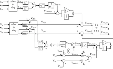
B. Series active filter control strategy
Series active filter is concerned for voltage compensation. Depending upon the type of load used, so many control strategies are being proposed. In this paper, the proposed strategy is the minimisation of the injected active power for a given apparent power. Synchronous d-q frame theory is applied to extract the reference voltage for the series APF as shown in Fig.2. For unbalanced Vs, the transformation to d-q axis is given by
(4)
Where T is given as follows:
cos cos
time it injects ac component of active power Pdvr ac. It helps to restore the negative component of voltage sags. The dc component of active power Pdvr dc can be calculated by the given equations.
/ (7)
Where Vdvrd dc and Vdvrq dc are:
V
dvrd dc
V
Ld
V
sd dc(8)
The perunit component of left hand side of series APF can be given by:
, / (9)
The perunit magnitude of fundamental components of voltage sag is applied to a non linear function to get the dc reference component of injected active power (Pdvr dc ref).The difference between reference values (Pdvr dc ref) and the feed back values (Pdvr dc) passes through the PI controller. The output of PI controller is added to the q axis ac component of Vs.
C. Cascaded multilevel inverter.
Cascaded multilevel inverters can be defined as power electronic devices that produces an output waveform of desired level by using input dc voltages[5]. High quality of the output quantities , ability to operate at high power and hihgh voltage and flexibility etc are some of the advantages of cascaded multilevel inverters .Smallest number of voltage level for a multilevel inverter using separate dc sources are three .For obtaining that ,a single H bridge is required.A cascaded multi level inverter is formed by connecting several H bridges in series. Each inverter will generate a square wave voltage wave form. Combining the waveform of each invters, the output waveform of cascaded multi level inverter will be formed
Fig. 3.control strategy for series filter.
There are mainly two types of cascaded multilevel inverters. They are (a)symmetrical type.
(b)asymmetrical type.
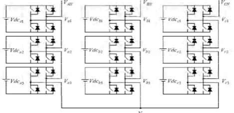
If the dc sources used in each inverter is equal, it is of symmetric type and if they are unequal, it is of asymmetric type. a seven-level cascaded multi level inverter is used in this paper.
Fig . 4. Three phase seven-level cascaded multi level inverter
III.SVPWM.
In multilevel inverters, several modulation techniques are used to reduce harmonics in sinusoidal signals. Space Vector Pulse Width Modulation can be defined as a vector approach to PWM technique in 3 phase inverters[2] .It is advantageous over the existing Sinusoidal PWM. The increasing trend of using SVPWM is due to its superior harmonic quality, ease of implementation and enhanced dc bus utilization.
In three phase inverters, there will be 8 switching states in total[7] . Out of which six are of active switching states and the other two are zero switching states. These vectors will form a hexagon in which six sectors will span 60 degree each. The reference voltage representing the three phase sinusoidal voltage in SVPWM can be constructed by switching between 2 nearest active vectors and zero vectors. The time of application of active vectors can also be found. The formulas used in SVPWM is given below.
Line to line voltages:
Vab = VaN - VbN
Vbc = VbN - VcN
Vca = VcN - VAn (10)
Phase voltages:
Van = 2/3VaN - 1/3VbN - 1/3VcN
Vbn = -1/3VaN + 2/3VbN - 1/3VcN
Vcn = -1/3VaN - 1/3VbN + 2/3VcN (11)
Fundamental Frequency Component (Vab)1
(12) Harmonic Frequency Components (Vab)h is given by:
(13)
Determine Vd, Vq, Vref, and angle () :
(14) 3,...) 2, 1, (n 1 6n h where, V 78 . 0 dc ab h (rms) ) (V h cn bn an cn bn q cn bn an cn bn an d V 2 3 V 2 3 V cos30 V cos30 V 0 V V 2 1 V 2 1 V cos60 V cos60 V V V dc dc
dc
6
V
0
.
78
V
frequency) l
fundamenta f
(where, s (16)
Calculation of Switching time duration at Sector 1 :
. . 2 3 . 1
0 . 2 3 . . 33 Where 0 60 (17)
dc ref s z 2 1 0 2 1V
3
2
V
a
and
f
1
T
where,
),
(
)
3
/
(
sin
)
(
sin
)
3
/
(
sin
)
3
/
(
sin
T
T
T
T
a
T
T
a
T
T
z z z
(18) III.GENETICALGORITHM.Genetic algorithm can be defined as a search algorithm based on natural selection and natural genetics. It can be used when no analytical formulation can be found for the mathematical description of the problem. The increasing tendency of using genetic algorithm in designing electronic circuits is due to the fact that it involves optimisation of a number of parameters[3]. When a vast range of possibilities are there in a problem, we use genetic algorithm to choose the appropriate solution.
When a specific problem is given, the input to genetic algorithm will be a set of potential solutions to that problem. A set of genes corresponding to a chromosome in a natural gene is referred to as strings in genetic algorithm. In this paper genetic algorithm is used in the shunt filter side for current compensation. The shunt active filter will inject some reference compensating current into the distribution system for compensating load current. Here genetic algorithm will help to choose the optimum reference signal out of possible solutions. In the simulation, it is given a population of 20 samples. Each sample is delayed by 1 unit time. Out of this 20 samples, GA will choose the optimum solution by performing cross over and mutation. A metric called fitness function will quantitatively evaluate each candidate to find the optimum solution.
V. SIMULATIOION AND EXPERIMENTAL RESULTS
Fig. 5. current compensation by shunt APF.
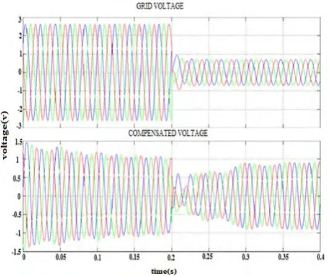
Fig. 6. Grid voltage and Compensated waveforms of series APF.
From FFT analysis, the THD of the load current is initially 26.5% . After doing current compensation by shunt active power filter, the THD is reduced to 2.29%. Thus a simultaneous compensation of current and voltage is obtained by the proposed system
VI. CONCLUSION
A novel control strategy for a wind power generating system using UPQC is proposed in this paper. Both series and shunt APF are used for voltage and current compensation respectively. A cascaded multilevel inverter with SVPWM is used to improve harmonic quality. Genetic algorithm is used in the control circuit of shunt APF to choose an optimal solution and to reduce the THD. The proposed system is simulated using Mtlab/simulink. Based on the simulation results ,it is shown that the proposed UPQC provides solutions for many power quality problems in a wind power system such as sag/ swell in the supply voltage, harmonics in the load current etc.
REFERENCES
[1] Ahmet Teke, Lütfü Saribulut, and Mehmet Tümay(2011), ‘ A Novel Reference Signal Generation Method for Power-Quality Improvement of Unified Power-Quality Conditioner’ IEEE Transactions On Power Delivery, vol. 26, no. 4, october 2011 2205. [2] Amit Kumar Gupta, and Ashwin M. Khambadkone,(2007), ‘ A General Space Vector PWM Algorithm for Multilevel Inverters,
Including Operation in Overmodulation Range’ IEEE Transactions On Power Electronics, Vol. 22, No. 2, March 2007 517.
[3] Babak Keshavarz Hedayati, and Abdolreza Rahmati(2010), ‘ Genetic Algorithm Application in Controlling Performance and Power Dissipation of Active Power Filters’ , Canadian Journal on Electrical & Electronics Engineering Vol. 1, No. 1, February 2010. [4] Bhim Singh, Kamal Al-Haddad, and Ambrish Chandra(1999), ‘ A Review of Active Filters for Power Quality Improvement’ IEEE
Transactions On Industrial Electronics, Vol. 46, No. 5, October 1999.
[5] Fang Zheng Peng, John W. McKeever, and Donald J. Adams (1998), ‘A Power Line Conditioner Using Cascade Multilevel Inverters for Distribution Systems’ IEEE transactions on industry applications, vol. 34, no. 6, november/december 1998 1293.
[6] Hideaki Fujitaand Hirofumi Akagi(1998), ‘ The Unified Power Quality Conditioner: The Integration of Series- and Shunt-Active Filters’ IEEE Transactions On Power Electronics, Vol. 13, No. 2, March 1998.
[7] P. Satish Kumar , J.Amarnath and S.V.L.Narasimham(2010), ‘ An Effective Space- Vector PWM Method for Multi-level Inverter Based on Two-level Inverter’ , International Journal of Computer and Electrical Engineering, Vol. 2, No.2, April, 2010 1793-8163 . [8] S.Sajedi, F. Khalifeh, T. Karimi,and Z. Khalifeh(2011), ‘Modeling and Application of UPQC to Power Quality Improvement