E-Mobility: smart grid and charging session of electric
vehicles
Gabriele Corzato*, Luca Secco^, Arslan Rasheed&, Atulya Kumar Nagar$, Emanuele Lindo Secco$
*Department of Industrial Engineering, University of Padova,
Via Venezia,1 Padova (PD), Italy
^DriWe, Contrà progresso, 1/H, Schio (VI), Italy &University of Auckland
$Robotics Lab, Department of Mathematics & Computer Science, Liverpool Hope
University, Hope Park, L16 9JD, Liverpool, UK
{[email protected],[email protected],
[email protected], [email protected],}
Abstract. In this contribution, we stress the importance of electric mobility in nowadays, since sales of Electric Vehicles (EV) in the world have exceeded one million cars and current number of charging stations are rapidly growing. In this context, this paper introduces a novel smart connection called DriWe between the EV, the charging point and the environment, in order to improve and consolidate the development of smart grids vs the charging enhancement. In DriWe, performance of the monophasic environment is optimized, providing support to the owner of the EV in order to (i) always achieve maximum power, (ii) easily reach the charging facilities through a special application that can be installed in tablet, smartphone or pc, and identify the various charge points (iii) guarantee the absence of electric blackout, thanks to a combination and an interaction of three elements: smart device, an intelligent framework, namely a DriWe cloud server and charge point. A dynamic load control method, which is based on an API (Application Programming Interface) with a 10 s frame rate update, is applied. The program runs within the end-user smart phone, acquires data from DriWe cloud server, and allows to coordinate the recharge column by allowing the electric vehicle supply equipment’s control and variation.
Keywords: Electric Vehicles, Smart Charging, Dynamic Control, Charging Station.
1.
Introduction
Furthermore, as automated and distributed energy network, the smart grid can be conceived as a two-way flow of electricity and communication, which allows monitoring everything from generation to consumer [2].
Basic support for the evolution of a society based on e-mobility will be given by the support of governments, which, after the Paris agreement on climate change, will have to commit themselves to adopt eco-sustainable solutions to solve environmental problems. The scenario of a planet in which electric cars are circulating is gaining more and more interest and importance and it is destined to become the indispensable promoter of sustainable mobility in the coming decades. "Consumers will not automatically switch to electric vehicles if the cost trend will stay high, if the charging station network is not ready, or if new technologies will not be easily usable" [3].
The easiest way to recharge EVs is the conductive wired charging, a physical connection between two different parts: car and a domestic plug, or an industrial plug or a charging column. Charging in monophasic environments occurs in alternating current. Nevertheless, according to recent investigations, car and domestic plug are not suitable for recharging vehicles for several hours to a current of 16 A due to frequent over-heating.
In AC conductive charging there are two different charging modes for an electric vehicle. Whether you use the connector supplied with the purchase of the EV, simply connect the two ends of the EVSE [4] (which have two types of electrical sockets) to the vehicle and the domestic plug or to the charging station, respectively. “If instead you use a solution where the cable is permanently connected to the charge point, and then supplied with it, you will have a single free connection terminal that will be inserted in the EV” [5].
2.
Materials & Methods
2.1 The problem
In a first instance the main problem or recharging an electric vehicle in a domestic or commercial environment, can be summarize as it follows: how to avoid the blackout of the building during the electric vehicle charging session?
In order to develop the DriWe system, we came across a relatively large and daily problem designed for families or small restaurants, shops and businesses that still want to offer better service to their customers and bring a structural benefit. Families are the strong point of this implementation, as the charging columns will be a strategic element in all homes.
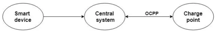
Communications are performed through an Open Charge Point communication Protocol (OCPP).
Figure 1 – The main functional blocks of the DriWe framework
The smart device must have some essential characteristics, such as reliability, speed of communication, immediate data transmission, small size but above all a low price.
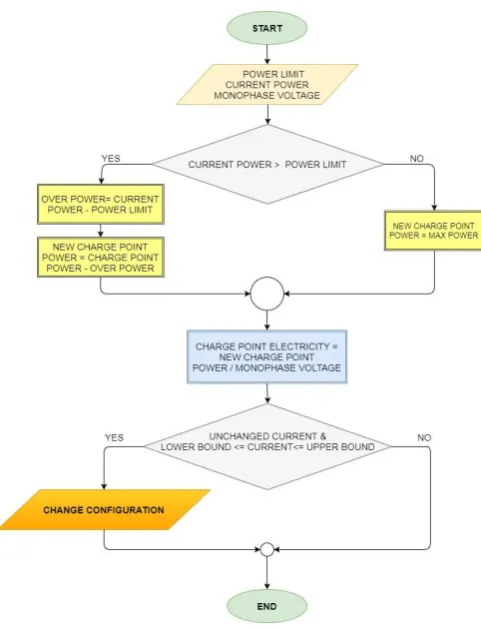
2.2 The optimization framework
The proposed framework is based on a block diagrammatic representation, which is quite schematic and easily understandable. The implemented program works by recalling the amount of absorbed loads power in the examined environment: this information is collected through a smart device via an API (Application Programming Interface) which updates every 10 seconds: (i) a sufficient time to prevent the electric meter from blowing if the contractual power limit is exceeded; (ii) time that avoids a clogging of the communication network. Accordingly, through the initialization of some variables (e.g. the contractual power limit, the monophasic voltage) and a mathematical algorithm checks whether the instantaneous power is higher or lower than the contracted limit power. In case:
The Current Power is greater than the Contractual Limit Power: we would have an excess power that will be subtracted from the charging power supplied by the charge point, and therefore no electrical blackout
The Current Power is less than the Contractual Limit Power: the charge point power supplied can be increased.
Therefore, it is possible to calculate the new current to be supplied by the charge point. This new current must be included within a range of values, a lower limit – namely 6 A, according to the CEI EN 61851-1 - and an upper limit, depending on the specifications and requirements of the charging station. The following configurations may occur:
The new value of the current is equal to the old one: the configuration parameters are not changed;
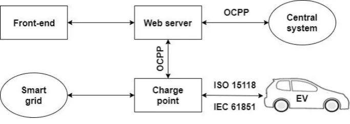
Figure 2 - The DriWe operating scheme (Wellisch, 2017)
Figure 3 – The functional flow chart of the calculation program
3.
Tests & Results
Different tests of the DriWe system have been performed on commercially available electric vehicles. In order to validate the system, different brands and types of vehicles have been used. On each test a full charging process has been performed. The tests were carried out at the DriWe laboratories. Each vehicle under examination was monitored for a period of 5 hours, where it was possible to notice the variation of the current supplied by the charging station vs the changes of the loads occurring in the laboratory. The measurements were performed via the calculation program which has been previously detailed.
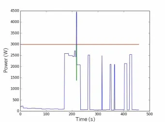
Renault Twizy - Figure 4 reports the performed output charging power in [W] vs the recharging time in [s]. The red line refers to the threshold power, namely the value of 3 [kW]. The graph shows how the system started with a simple monitoring of the loads in the environment under examination, then with the start of the recharge phase at time [s] an increase in the power absorbed by the network can be noticed; nevertheless, with the consequent introduction of a further electric load, the total instantaneous power exceeds the simulated contractual power limit of 3 [kW]. The calculation program will then be activated with a consequent reduction in the current supplied to the vehicle.
Figure 4 – The Renault Twizy charging pattern
The last part of the graph shows a series of power peaks due to the recharging phase of the vehicle with its consequent detachment. As it can be observed, the recharge session does not result to be successful because changing the current from management there is a communication error given by the absence of the pilot control, "a control conductor in the power cable connecting the control box on the cable or in the fixed part of the EVSE, and the ground of the EV through the control circuit on the vehicle” [7],which does not allow a correct modulation of the signal and therefore a variation of the current.
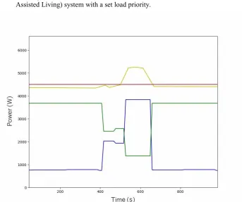
the line of instantaneous absorbed power – namely the loads plus the charging station - constantly follows the red line or the contracted power line at 4.5 [kW].
This pattern shows the correct functioning of the calculation program: in fact, when the loads - blue line in the graph - varies within the examined environment, then a correct modulation of the current supplied to the vehicle is obtained, always allowing maximum recharging power and avoiding exceeding the contractual limit and the risk of electric blackout. For instance, when the blue line is overtaken - from 0.75 [kW] to 2.03 [kW] in the figure – then, the current and the maximum power of the charging station decreases from a value of 16 [A] to 10.70 [A] and from 3.68 [kW] to 2.46 [kW], respectively, however the instantaneous absorbed power is constant.
Table 1: phases recharge Nissan Leaf
Blu line Power loads [kW] Charging Station current [A] Green line Maximum power charge point [kW] Yellow line Instantaneous absorbed power [kW]
0,80 15,60 3,58 3,58+0,80≈4,40
0,75 16,00 3,68 3,68+0,75≈4,40
2,03 10,70 2,46 2,46+2,03≈4,50
1,95 11,10 2,55 2,55+1,95=4,50
3,90 6,00 1,38 1,38+3,90≈5,30
0,80 16,00 3,68 3,68+0,80≈4,50
By analyzing the central part of the graph, it can be noticed a greater absorption of the loads present in the examined environment, making it possible to exceed the contractual threshold up to 5.3 [kW]. The dynamic modulation system, to stay below the 4.5 [kW] threshold, would have to supply about 2.5 [A], but the recharge column has a lower supply limit of at least 6 [A] as it was mentioned beofre.
The above table (Table 1) reports the main values of the power loads, charging station current and the performed instantaneous and maximum power.
Nevertheless, a threshold overrun has occurred but there is not an electric blackout. In order to solve this problem, the following strategies maybe adopted with the aim:
To provide for the immediate sending of a message (i.e. SMS, e-mail or display) to the user to make him aware of the exceeding of contractual power and the risk of electric blackout if the power of the loads is not reduced. To integrate the solution with a home automation device or AAL (Ambient
Assisted Living) system with a set load priority.
Fig 5: The Nissan Leaf charging pattern
4.
Conclusions
A future development consists in interfacing the electricity meter with the charging station through the communication on the appropriate Chain 2 channel. It is therefore necessary to carry out a data transmission by means of the Power Line Carrier (PLC) communication channel, using appropriate waves conveyed on the wiring systems that connect the meter directly to the relative user device, in order to be able to modulate the power supplied by the charging station.
5.
Acknowledgments
We thank you all staff of the DriWe Company for their valuable support and in particular: Mr. Alessio Vitella.
This work was presented in thesis form in fulfilment of the requirements for the MsC in Energy Engineering for the student G. Corzato at the Department of Industrial Engineering, University of Padova, Italy.
References
[1] Irena.org. (2017) [online] Available at:
http://www.irena.org/documentdownloads/publications/smart_grids.pdf [Accessed 15 Dec. 2017].
[2] Iea.org. (2017) [online] Available at:
https://www.iea.org/publications/freepublications/publication/smartgrids_roadmap.pdf [Accessed 15 Dec. 2017].
[3] Aci.it. (2017) [online] Available at:
http://www.aci.it/fileadmin/immagini/Notizie/Mobilita/FIA_E-mobility.pdf [Accessed 15 Dec. 2017].
[4] U. Abronzini et al., "Optimal energy control for smart charging infrastructures with ESS and REG," 2016 International Conference on Electrical Systems for Aircraft, Railway, Ship Propulsion and Road Vehicles & International Transportation Electrification Conference (ESARS-ITEC), Toulouse, 2016, pp. 1-6.
[5] “Fattibilità tecnologica per il controllo dinamico dei carichi in ambiente monofase, durante la ricarica di veicoli elettrici”, Gabriele Corzato, Università degli studi di Padova, 2017.
[6] Á. Rodríguez-Serrano, A. Torralba, E. Rodríguez-Valencia and J. Tarifa-Galisteo, "A communication system from EV to EV Service Provider based on OCPP over a wireless network," IECON 2013 - 39th Annual Conference of the IEEE Industrial Electronics Society, Vienna, 2013, pp. 5434-5438.
[7] “Sistema di ricarica conduttiva dei veicoli elettrici, Parte 1: prescrizioni generali”, Norma CEI EN 61851-1, 2012.
[9] L. Secco, A. Alberti, E.L. Secco, MOB-Y: Smart Grid for sustainable MOBility with retrofit Electric Vehicles, The 3rd IEEE International Conference on Cybernetics (CYBCONF-2017), 21-23 June 2017, DOI: 10.1109/CYBConf.2017.7985790.