Gateway Node-Based Greedy Routing
Algorithm for Efficient Packet Forwarding
in Vehicular Ad Hoc Networks
Mohamed Abbas A
Assistant Professor (SG), Department of Computer Applications, B.S. Abdur Rahman Crescent Engineering College, Chennai
Tamilnadu, INDIA. Email: [email protected]
Dr. Sheik Abdul Khader P
Professor and Head, Department of Computer Applications, B.S. Abdur Rahman Crescent Engineering College, Chennai
Tamilnadu, INDIA. Email: [email protected]
Dr. Munir Ahamed Rabbani M
Assistant Professor, College of Computer, Quassim University, Saudi Arabia Email: [email protected]
Abstract
In recent years, vehicular communications are one of the hottest research topics. It has also gained much attention in industry as well as academia. Vehicular Ad Hoc Networks (VANETs) are advances of the wireless communication technologies. Routing is one of the key research issues in VANETs as long as it plays an important role in public safety and commercial applications. In VANET, routing of data is a challenging task due to high speed of nodes (i.e., vehicles) movement and rapidly changing topology. Recent research showed that existing routing algorithm solutions for Mobile Ad Hoc Networks (MANETs) are not able to meet the unique requirements of vehicular networks. In this paper, we propose Gateway Node-Based Greedy Routing (GNGR), a reliable greedy position-based routing approach algorithm. In GNGR, we forward the packets to any of the nodes in the corner of the transmission range of source/forwarding node as most suitable next hop. With this consideration, the nodes move towards the direction of the destination. We propose Dynamic Transition Mobility Model (DTMM) to evaluate our routing technique. This paper gives a complete description of our packet forwarding approach and simulation results. The simulation results are carried out based on Packet Delivery Ratio (PDR). Our routing technique is compared with other routing techniques; the PDR is improved significantly compared with other routing techniques of VANET.
Keywords: Vehicular Ad Hoc Networks, Gateway Node Based Greedy Routing, Dynamic Transition Mobility Model, Packet Delivery Ratio.
1. Introduction
Vehicular Ad Hoc Networks (VANETs) are special cases Mobile Ad Hoc Networks (MANETs). VANETs are distributed, self-organizing communication networks between moving vehicles. The Intelligent Transportation Systems (ITS) have been developed to improve safety, security and efficiency of transportation systems for traveling, which apply rapidly emerging information technologies in vehicles and transportation infrastructures. Inter-Vehicle Communication (IVC) is essential to the ITS, which aims at enhancing the public and private safety as well as increasing the efficiency of the transportation system. The Dedicated Short Range Communications (DSRC) system is developed based on IEEE 802.11 WLAN technologies for the purpose of exchanging information among vehicles. The field of Inter Vehicular Communications, including both vehicle-to-vehicle communications (V-V) and vehicle-to-roadside communications (V-R), also known as VANETs, is recognized as an important component of ITS.
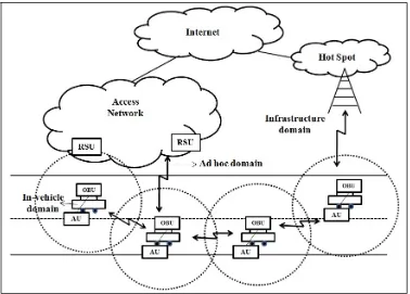
In-vehicle domain is a local network between vehicles and this network is composed of two types of units: (1) On-Board Units (OBUs) and (ii) one or more Application Units (AUs). An OBU is a communication capability (Wired and/or Wireless) device and AU is a device executing one or more applications. These applications make use of the OBU communication capabilities. The AU is a portable device such as laptop or PDA connected with OBU. Usually, the connection between OBU and AU is either wired or wirelessly connected using Bluetooth, WUSB or UWB. Both the units are working in different operation and reside on the same physical unit. In an ad hoc domain, the vehicle networks are equipped with OBUs and Road Side Units (RSUs). The RSUs are fixed on the side of roads. The various moving vehicles of OBUs form a network called MANET and here OBUs are equipped with communication devices, including at least a short range wireless communication device dedicated for road safety. Mobile nodes of OBUs and static nodes of RSUs can be seen as nodes of an ad hoc network. An RSU which can be attached to an infrastructure network can be used to connect with the Internet. The primary objective of RSU is to improve road safety by sending, receiving, or forwarding data in the ad hoc domain. RSUs can be communicated directly with each other or via multi hop. There are two accesses in an infrastructure domain. They are RSU and Hot Spot. RSUs are permitted to access the infrastructure by OBUs and thus, OBUs are to be connected to the Internet. OBUs may communicate with Internet via public, commercial, or private hot spots (Wi-Fi hot spots). If OBUs are integrated with cellular radio networks, they can also be utilizing cellular radio networks communication capabilities even if RSUs and Hot Spots are not available.
The rest of the paper is organized as follows: In Section 2, the background and related work will be presented. In Section 3, we propose new routing algorithm called Gateway Node Based Greedy Routing Algorithm (GNGR). In Section 4, we present the simulation results and analysis.
2. Background and Related Work
In this section, we briefly summarize the characteristics of VANETs related to routing and also survey the existing routing schemes of VANETs.
2.1 VANETs Characteristics
In the following, vehicular networks have special behavior and characteristics and it is distinguished from other types of mobile networks [2] [3].
Unlimited transmission power: Mobile device power issues are not a significant constraint in vehicular Networks, since the node (vehicle) itself can provide continuous power to computing and communication devices.
High computational capability: Operating vehicles can afford significant computing, communication and sensing capabilities.
Predicable Mobility: Unlike classic mobile ad hoc networks, where it is hard to predict the nodes’ mobility, vehicles tend to have very predictable movements that are (usually) limited to roadways. The movement of nodes in VANETs is constrained by the layout of roads. The vehicles are communicating among each other directly when they are within the transmission range. Roadway information is often available from positioning systems and map based technologies such as Global Positioning System (GPS).
Potentially large scale: Unlike most ad hoc networks studied in the literature that usually assume a limited network size, vehicular networks can be extended over the entire road network and include many participants.
High Mobility: Vehicular network scenarios are very different from classic ad hoc networks. In VANETs, vehicles can move fast. It can join and leave the network much more frequently than MANETs. On highways, relative speeds of up to 160 km/h may occur, while density of nodes may be 2-3 vehicles in 1 km on low busy roads. On the other hand, in the city, relative speeds can reach up to 40 km/h and nodes’ density can be very high, especially during rush hour.
Partitioned network: Vehicular networks will be frequently partitioned. The dynamic nature of traffic may result in large inter-vehicle gaps in sparsely populated scenarios and hence in several isolated clusters of nodes.
Network connectivity: The degree to which network is connected is highly dependent on two factors: the range of wireless links and the fraction of participant vehicles, where only a fraction of vehicles on the road could be equipped with wireless interfaces.
2.2 MANETs Routing Protocols
The routing protocols in MANETs can be classified into two categories, proactive and reactive and they can be classified by their properties.
2.2.1 Proactive routing protocols
The proactive routing protocols are based on the table-driven approach. In Table-Driven routing algorithm (e.g., DSDV [10], OLSR [11]), every node maintains the network topology information in the form of routing tables by periodically exchanging routing information. Routing information is generally flooded in the whole network. Whenever a node requires a path to a destination, it runs an appropriate path-finding algorithm on the topology information it maintains, even if these paths are not currently used. The main drawback here is that the maintenance of un-used paths may become a significant part of the available bandwidth if the network topology changes frequently. In the case of vehicular networks, the movement of vehicles are extremely so dynamic so that we did not further investigate proactive approaches.
2.2.2 Reactive routing protocols
To overcome this kind of limitation, a Position-based routing algorithm has been introduced (e.g., GPSR [15], terminodes routing [16]). Position based routing protocol requires information about the physical position of the participating nodes. Routing decision at each node is then based on destination’s position contained in the packet and the position of forwarding node’s neighbors.
2.3 VANETs Routing Protocols
Following are a summary of representative VANETs routing algorithms.
2.3.1 GSR (Geographic Source Routing)
Lochert et al. in [4] proposed GSR, a position-based routing with topological information. This approach employs greedy forwarding along a pre-selected shortest path. The simulation results show that GSR outperforms topology based approaches (AODV and DSR) with respect to packet delivery ratio and latency by using realistic vehicular traffic. But this approach neglects the case that there are not enough nodes for forwarding packets when the traffic density is low. Low traffic density will make it difficult to find an end-to-end connection along the pre-selected path.
2.3.2 GPCR (Greedy Perimeter Coordinator Routing)
To deal with the challenges of city scenarios, Lochert et al. designed GPCR in [5]. This protocol employs a restricted greedy forwarding procedure along a preselected path. When choosing the next hop, a coordinator (the node on a junction) is preferred to a non coordinator node, even if it is not the geographical closest node to destination. Similar to GSR, GPCR neglects the case of low traffic density.
2.3.3 A-STAR (Anchor-based Street and Traffic Aware Routing)
To guarantee an end-to-end connection even in a vehicular network with low traffic density, Seet et al. proposed A-STAR [6]. A-STAR uses information on city bus routes to identify an anchor path with high connectivity for packet delivery. By using an anchor path, A-STAR guarantees to find an end-to-end connection even in the case of low traffic density. This position-based scheme also employs a route recovery strategy when the packets are routed to a local optimum by computing a new anchor path from local maximum to which the packet is routed. The simulation results show A-STAR achieves obvious network performance improvement compared with GSR and GPSR. But the routing path may not be optimal because it is along the anchor path. It results in large delay.
2.3.4 MDDV (Mobility-Centric Data Dissemination Algorithm for Vehicular Networks)
To achieve reliable and efficient routing, Wu et al. proposed MDDV [7] that combines opportunistic forwarding, geographical forwarding, and trajectory-based forwarding. MDDV takes into account the traffic density. A forwarding trajectory is specified extending from the source to the destination (trajectory-based forwarding), along which a message that will be moved geographically closer to the destination (geographical forwarding). The selection of forwarding trajectory uses geographical knowledge and traffic density. MDDV assumes traffic density is static. Messages are forwarded along forwarding trajectory through intermediate nodes which store and forward messages opportunistically. This approach focuses on reliable routing. But trajectory-based forwarding will lead to large delay if the traffic density varies by time.
2.3.5 VADD (Vehicle-Assisted Data Delivery)
To guarantee an end-to-end connection in a sparse network with tolerable delay, Zhao and Cao proposed VADD [8] based on the idea of carry and forward by using predicable mobility specific to sparse networks. Instead of routing along a preselect path, VADD chooses next hop based on highest pre-defined direction priority by selecting the closest one to destination. Their simulation results show VADD outperforms GPSR in terms of packet delivery ratio, data packet delay, and traffic overhead. This approach predicts the directions of vehicles movement. But it doesn’t predict the environmental change in the future.
2.3.6 PDGR (Predictive Directional Greedy Routing)
The various routing protocols of MANETs and VANETs are analyzed and drawbacks of those routing protocols are described below.
2.4 Gaps of MANETs and VANETs Routing Protocols
2.4.1 MANETs Routing Protocol
• AODV - Large latency of packet transmission • DSR - Large latency of packet transmission
• OLSR - High bandwidth consumption due to dynamic topology.
• GPSR - Frequent network disconnection, Routing loops, Too many hops and Wrong direction.
2.4.2 VANETs Routing Protocol
• GSR - End to end connection is difficult in low traffic density • GPCR - End to end connection is difficult in low traffic density
• A-STAR - Routing paths are not optimal and results in large delay of packet transmission. • MDDV - Large delay if the traffic density varies by time
• VADD - Large delay due to varying topology and varying traffic density
• PDGR - Too many hops, Large Delay if the traffic density is high and Low Packet delivery ratio.
3. Proposed Routing Algorithm
3.1 Gateway Node-Based Greedy Routing Algorithm (GNGR)
GNGR is a greedy position based reliable routing algorithm and it is designed for sending messages from any node to any other node. In this, the sending of message is from one node to another node (i.e., Unicast) or from one node to all other nodes (i.e., Broadcast/Multicast) in a vehicular ad hoc network. The common design goals of GNGR algorithm are to deliver messages with high reliability and to optimize packet behavior for ad hoc networks with high mobility.
There are six basic functional operations of GNGR algorithm. i. Identification of Neighbor Node (INN)
ii. Calculation of Distance (CD) between nodes
iii. Identification of Moving Direction (IMD) of the nodes iv. Link Stability Calculation (LSC) between nodes
v. Weighted Score Calculation (WSC) to identify the next hop which is closer to the destination vi. Gateway Node Selection (GNS).
At any point of time the INN takes the responsibility for collection of all neighbor nodes information, which is all present within the transmission range of source/forwarder node. The CD takes the responsibility for calculating the closeness of next hop using distance information from the GPS. The IMD takes the responsibility to identify the direction of motion of neighbor nodes and verifies that these nodes are moving towards the direction of destination. The LSC takes the responsibility for calculating the link stability between the source/forwarder node and its corresponding neighbor nodes. The WSC takes the responsibility for calculating the largest weighted score and also identify the largest weighted score neighbor node which is further forwarding of a particular packet to destination. The GNS takes the responsibility for selection of gateway node and this node will have high weighted score in different levels of transmission range. In the following section, the general assumptions of GNGR algorithm are discussed.
3.2 Assumptions
We assume that every vehicle is equipped with special device (ie., OBU), static digital maps, GPS receiver. With help of OBU, vehicles can communicate with one another within each ones radio transmission range and GPS receivers get their accurate geographical location. This geographical location gives the location of destination well in advance, so that the source/forwarder node can send packets to a destination. We also assume each vehicle has the knowledge of its own velocity and direction.
3.3 Gateway Node Selection
increase packet delivery ratio, minimize end to end delay and avoid packet loss. The Highest Transmission Range (HTR) of a vehicle/node is 250m and other different stages of transmission ranges are 200m, 150m, 100m and 50m, which are considerably lower than HTR.
Pseudo Code for GNGR
currentnode : the current node packet ∝, , : Weighted Score factors
1. Calculation of Distance between nodes ← Closeness of nexthop
2. Identification of Moving Direction of the nodes ← Cosine value of angle made by these vectors
3. Shortest distance from packet forwarding node c to destination D = Distance between current node location and destination node location 4. Vector for the location of gateway node i to the location of destination node D = Destination node location
– Current node location 5. Weighted Score of the node = ×Cosine value of the speed of vector for current node and vector for the
location of current node to the location of destination node.
6. nextHop = currentnode
7. for all neighbors of currentnode do
8. get the location of the i node neighbor, get the speed of i node neighbor, get the distance between destination node location and i node location, get the distance between current node location and i node location
9. for all neighbors of currentnode with distance between current node location and i node location do
10. if (distance between current node location and i node location is less than 250 m AND distance between current node location and i node location is greater than 200 m)
11. Vector for the location of gateway node i to the location of destination node D = Destination node location – Current node location 12. Weighted Score of the i node = ∝ × Calculation of Distance between nodes + × Identification of
Moving Direction of the nodes + × Link Stability between current node and i node 13. for i node of neighbor with greater Weighted Score of the i node do
14. Weighted Score of the node = Weighted Score of the i node 15. nextHop = neighi
16. end for
17. else if (distance between current node location and i node location is less than 200 m AND distance between current node location and i node location is greater than 150 m)
18. Vector for the location of gateway node i to the location of destination node D = Destination node location – Current node location 19. Weighted Score of the i node = ∝ × Calculation of Distance between nodes + × Identification of
Moving Direction of the nodes + × Link Stability between current node and i node 20. for i node of neighbor with greater Weighted Score of the i node do
21. Weighted Score of the node = Weighted Score of the i node 22. nextHop = neighi
23. end for
24. else if ((distance between current node location and i node location is less than 150 m AND distance between current node location and i node location is greater than 100 m)
25. Vector for the location of gateway node i to the location of destination node D = Destination node location – Current node location 26. Weighted Score of the i node = ∝ × Calculation of Distance between nodes + × Identification of
Moving Direction of the nodes + × Link Stability between current node and i node 27. for i node of neighbor with greater Weighted Score of the i node do
28. Weighted Score of the node = Weighted Score of the i node 29. nextHop = neighi
30. end for
31. else if (distance between current node location and i node location is less than 100 m AND distance between current node location and i node location is greater than 50 m)
32. Vector for the location of gateway node i to the location of destination node D = Destination node location – Current node location 33. Weighted Score of the i node = ∝ × Calculation of Distance between nodes + × Identification of
Moving Direction of the nodes + × Link Stability between current node and i node 34. for i node of neighbor with greater Weighted Score of the i node do
36. nextHop = neighi
37. end for
38. else if (distance between current node location and i node location is less than 50 m)
39. Vector for the location of gateway node i to the location of destination node D = Destination node location – Current node location 40. Weighted Score of the i node = ∝ × Calculation of Distance between nodes + × Identification of
Moving Direction of the nodes + × Link Stability between current node and i node 41. for i node of neighbor with greater Weighted Score of the i node do
42. Weighted Score of the node = Weighted Score of the i node 43. nextHop = neighi
44. end for
45. else
46. carry the packet with currentnode 47. end if
48. end for
49. end for
4. Simulation Results and Analysis
In this section, we evaluate the performance of routing protocols GPSR, PDGR and GNGR in an open environment.
4.1 Dynamic Transition Mobility Model (DTMM)
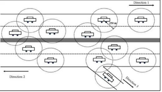
We use mobility model called Dynamic Transition Mobility Model (DTMM) as shown in Fig. 2. This mobility model can be used to simulate the movement pattern of moving vehicles on streets or roads that are defined by maps from the GPS, equipped in these vehicles. DTMM works on the basic idea that vehicles which move on roads can communicate directly with each other or through multiple hops transmission in the form of VANET. In DTMM, vehicles or nodes are randomly distributed on roads with linear node density and road includes two or more lanes. The vehicles are designed to move in different speeds and directions (Vertical and Horizontal). Vehicle moving in vertical roads indicate that the cars travel in north/south direction and horizontal road shows east/west direction. Security distance is maintained between two subsequent vehicles in a lane. Vehicles can move in desired direction based on the place of destination vehicle at the junction of the roads. Vehicles can transmit the packet in both directions. In this model, deterministic and instantaneous transmission mechanism is followed, because, the transmission of packet is within a certain radius r=250m from the sender. Within this transmission range, vehicles can unicast, multicast and broadcast packets to the neighbouring vehicles. Vehicles are also allowed to overtake the preceding vehicle during packet transmission.
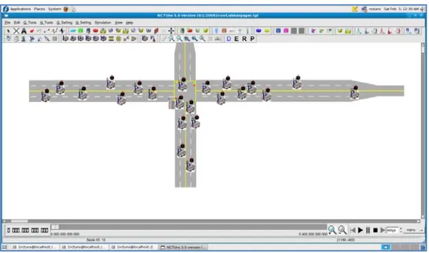
The simulation that was conducted on network simulator is NCTUns5.0 [17]. NCTUns 5.0 is a network simulator and emulator. It includes provision for vehicular traffic simulation. It is open-source and runs on Linux. It directly uses Linux TCP/IP protocol stack. It can use any real –life existing or to be developed UNIX application program as a traffic generator program. It provides a highly-integrated and professional GUI environment as shown in the Fig.3. The GUI supports the desired road network construction and road information is stored in road network specification file.GUI allows to specify different car profile setting and it is stored in car profile file.
The movement of vehicles was controlled by setting vehicle movement and information related to this is stored in node movement scenario configuration file. Simulations for each of the routing protocols were carried out with varying number of nodes with specific parameters. The IEEE 802.11 Distributed Coordination Function (DCF) was used as the Medium Access Control Protocol. The packet size was fixed to 512 Bytes. The Traffic source was UDP. Initially the nodes were placed at certain specific locations, and then the nodes were moved with varying speeds towards new locations. The parameters related to mobility model and wireless communications are shown in Table 1. We used a 1000m×1000m square street area for simulation, the number of vehicles travelling on the road ranges from 10 to 100 and constant bit rate was 2 (Packets/Second). In this scenario all vehicles are communicate with transmission range of 250 meters.
Parameters Settings
Simulation Area 1000m x 1000m Number of Vehicles 10 – 100
Mobility of Vehicles 0 – 50 (meter/second) Number of Packet Senders 30
Transmission Range 250m
Constant Bit Rate (CBR) 2 (packets/second)
Packet Size 512 Bytes
Vehicle beacon interval 0.5 (seconds) MAC Protocol 802.11 DCF
The following metric is considered to evaluate simulation results:
Packet Delivery Ratio (PDR): the ratio of packets that successfully reach destination to the original sent ones.
4.2 Packet Delivery Ratio vs. Mobility
In this division, packet delivery ratio is compared with different speed of vehicles as shown in Fig.4. The packet delivery ratio of GPSR and PDGR decreases due to increase in the speed of vehicles. The high speed of vehicles paves way for the packet loss at the corner of highest transmission range. In GPSR and PDGR, packet loss is high as compared to other VANETs routing protocols. By increasing the speed of vehicles, the packet loss at the corner of highest transmission range is reduced considerably in GNGR and PDR is also improved to 13.8% as compared with PDGR.
Table 1: Simulation Parameters
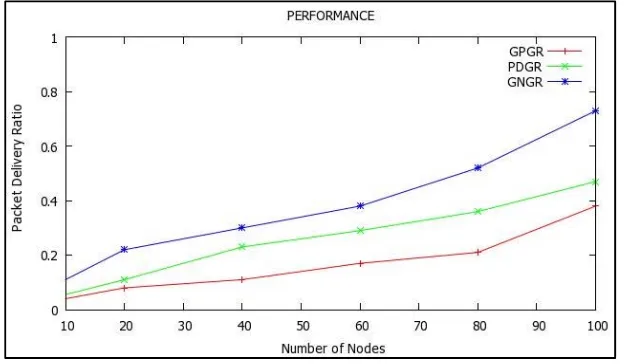
4.3 Packet Delivery Ratio vs. Number of Nodes
In this division, packet delivery ratio is compared with number of nodes as shown in Fig.5. In the beginning, the packet delivery ratio is less due to less number of vehicles for GPSR, PDGR and GNGR. The packet delivery increases depending on the increase of nodes in the routing algorithms. GPSR increases delay of packet transmission, when it switches to perimeter mode in case of no node is available. The packet delivery ratio is high for PDGR as compared with GPSR. In PDGR, next hop selection for packet forwarding is done through prediction and it is not reliable at all situations. When the vehicles are moving in high speed, the packet forwarded to the corner of transmission range will be lost. To overcome this kind of situation, the GNGR uses weighted score calculation for selection of next hop. By increasing the number of vehicles, the GNGR reduces the packet loss at highest transmission range and also packet delivery ratio increases as compared with PDGR for 12.4%.
4.4 Packet Delivery Ratio vs. Transmission Range
In this division, packet delivery ratio is compared with various transmission ranges as shown in Fig.6. In GPSR, packet forward approach is used for one hop neighbor. In the case of PDGR, two hop neighbors are used to forward the packet. However, as number of neighbors starts increasing in the road network, numbers of hops are also increased in GPSR and PDGR. When the number of hops increases, packet delivery ratio decreases. To
Fig 4: Packet Delivery Ratio vs. Mobility
overcome this kind of situation, the neighbor node selection is based on the various levels of transmission range (ie., 250m, 200m, 150m, 100, 50m) using distance information from GPS. Number of hops is reduced reasonably by using various transmission ranges in GNGR and also the packet delivery ratio improved to 16.2% as compared with PDGR.
5. Conclusion
In this paper we have analyzed the various routing characteristics of VANETs and identified the properties of VANETs. The contributions and limitations of MANETs, VANETs were presented. The various unique characteristics of VANET were compared with MANET. We have proposed new mobility model called Dynamic Transition Mobility Model and also position based greedy routing approach GNGR. The GNGR, GPGR and PDGR were compared in terms of packet delivery ratio. The simulation result shows GNGR significantly improves packet delivery ratio. In the future, our approach requires modifications to city environment characteristics and different mobility models with obstacles. The proposed GNGR routing algorithm approach when compared with other existing approach, gives an improvement of packet delivery ratio over other routing approach.
References
[1] Car 2 Car Communication Consortium Manifesto, work in progress, May 2007.
[2] M. Nekovee, “Sensor networks on the road: the promises and challenges of vehicular ad hoc networks and vehicular grids,” In Proc. Of the Workshop on Ubiquitous Computing and e-Research, Edinburgh, UK, May 2005.
[3] J. Blum, A. Eskandarian, and L. Hoffmman, “Challenges of intervehicle ad hoc networks,” IEEE Trans. Intelligent Transportation Systems 5(4), December 2004, pp. 347-351.
[4] C. Lochert, H. Hartenstein, J. Tian, D. Herrmann, H. Fubler, M. Mauve: “A Routing Strategy for Vehicular Ad Hoc Networks in City Environments”, IEEE Intelligent Vehicles Symposium (IV2003).
[5] C. Lochert, M. Mauve, H. Fler, H. Hartenstein. “Geographic Routing in City Scenarios” (poster), MobiCom. 2004, ACM SIGMOBILE Mobile Computing and Communications Review (MC2R) 9 (1), pp. 69–72, 2005.
[6] B.-C. Seet, G. Liu, B.-S. Lee, C. H. Foh, K. J. Wong, K.-K. Lee. “A-STAR: A Mobile Ad Hoc Routing Strategy for Metropolis Vehicular Communications”, NETWORKING 2004.
[7] H. Wu, R. Fujimoto, R. Guensler and M. Hunter. “MDDV: A Mobility-Centric Data Dissemination Algorithm for Vehicular Networks”, ACM VANET 2004.
[8] J. Zhao and G. Cao. “VADD: Vehicle-Assisted Data Delivery in Vehicular Ad Hoc Networks”, InfoCom 2006.
[9] Jiayu Gong, Cheng-Zhong Xu and James Holle. “Predictive Directional Greedy Routing in Vehicular Ad hoc Networks”, (ICDCSW’ 07).
[10] Charles E. Perkins and Pravin Bhagwat, “Highly dynamic destination-sequenced distance-vector routing (DSDV),” in Proceedings of ACM SIGCOMM’94 Conference on Communications Architectures, Protocols and Applications, 1994.
[11] T. H. Clausen and P. Jacquet. “Optimized Link State Routing (OLSR)”, RFC 3626, 2003.
[12] David B. Johnson and David A. Maltz, “Dynamic Source routing in ad hoc wireless networks,” in Mobile Computing,Tomasz Imielinske and Hank Korth, Eds., vol. 353. Kluwer Academic Publishers, 1996.
[13] Vincent D. Park and M. Scott Corson, “A highly adaptive distributed routing algorithm for mobile wireless networks,” in Proceedings of IEEE INFOCOMM, 1997, pp. 1405–1413.
[14] Charles E. Perkins and Elizabeth M. Royer, “Adhoc on-demand distance vector routing,” in Proceedings of the 2nd IEEE Workshop on Mobile Computing Systems and Applications, February 1999, pp. 1405–1413.
[16] Ljubica Blazevic , Silvia Giordano , and Jean- Yves Le Boudec , “Self-organizing wide-area routing,” in Proceedings of SCI 2000/ISAS 2000,Orlando, July 2000.