Mixing and internal dynamics of droplets impacting and coalescing on a solid surface
J. R. Castrej´on-Pita, K. J. Kubiak§, A. A. Castrej´on-Pita, M. C. T. Wilson§, and I. M. Hutchings Department of Engineering, University of Cambridge,
17 Charles Babbage Road, Cambridge, CB3 0FS, United Kingdom. and
§School of Mechanical Engineering, University of Leeds, Leeds, LS2 9JT, United Kingdom
The coalescence and mixing of a sessile and an impacting liquid droplet on a solid surface are studied experimentally and numerically in terms of lateral separation and droplet speed. Two droplet generators are used to produce differently coloured droplets. Two high speed imaging systems are used to investigate the impact and coalescence of the droplets in colour from a side view with a simultaneous grey-scale view from below. Millimetre-sized droplets were used with dynamical conditions, based on the Reynolds and Weber numbers, relevant to microfluidics and commercial inkjet printing. Experimental measurements of advancing and receding static contact angles are used to calibrate a contact angle hysteresis model within a lattice Boltzmann framework, which is shown to capture the observed dynamics qualitatively and the final droplet configuration quantitatively. Our results show that no detectable mixing occurs during impact and coalescence of similar-sized droplets, but when the sessile droplet is sufficiently larger than the impacting droplet vortex ring generation can be observed. Finally we show how a gradient of wettability on the substrate can potentially enhance mixing.
Keywords: Droplets, Coalescence, Mixing, Lattice Boltzmann.
PACS numbers: 47.55.db (Drop and bubble formation) and 47.80.Jk (Flow visualization and imaging)
I. INTRODUCTION
Coalescence and mixing of droplets on a solid surface are of great interest not only to the established inkjet printing industry, but also to emerging applications such as the non-contact printing of functional electronics and biological materials, and in the fields of microfluidic de-vices, microchemistry and fast prototyping [1–5]. The advantages of the inkjet printing of liquid materials over traditional delivery techniques are many and based on the technological ability of printheads to generate ho-mogeneously sized droplets on demand at a determined speed and direction. These characteristics create a sce-nario where precise volumes of reagents and/or reac-tive components can be dispatched at a specific loca-tion at precise times. The process of non-contact print-ing involves the generation, deposition and coalescence of droplets to make patterns for graphics applications or three-dimensional structures in other manufacturing processes [6]. In graphical applications, the coalescence of droplets on a substrate needs to be controlled to re-duce pixelation and increase the resolution of printing. In contrast, in additive manufacturing applications such as in the synthesis of nylon 6 in situ via inkjet print-ing of reactive fluids, good mixprint-ing durprint-ing drop-on-drop deposition is essential [7].
For printing applications, it is the coalescence and mix-ing of consecutively printed droplets (i.e. the impact of a falling droplet onto a sessile droplet) that is of particu-lar importance. Regardless this, most previous studies in droplet deposition have focused only on the external dy-namics — e.g. the free-surface shape, extent of spreading, and final footprint of the composite droplet [8–13] — and only a few works have explored the internal dynamics or mixing [5,7,14,15].
Castrej´on-Pitaet al. [14] used particle image velocime-try (PIV) within millimeter-size droplets to observe the internal fluid velocity field during the coalescence of a sessile droplet and an impacting one. Yanget al. [5] ex-plored the movement of fluorescent particles during evap-oration of a composite droplet formed from two consec-utively printed droplets, focusing on particle deposition dynamics. Both of the above works relied on viewing the coalescence process from below and using transpar-ent droplets, so that (in the case of PIV) seeding particles could be identified and analyzed to compute the internal flow. Due to the statistical nature of the PIV algorithms, the method does not rely on the identification of individ-ual tracking particles or fluid features, and so the study of mixing is impossible with that technology. The PIV flow visualisations were also limited essentially to one plane within the flow.
(more than 80%) was achieved, with unmixed regions confined to the edges of the contact area, but again the visualisation was not able to reveal the three-dimensional dynamics of the ‘interface’ between the two liquids being mixed.
FIG. 1: (Colour online) Schematic diagram of the two-droplet generator system. The generator on the left contains an un-coloured mixture of glycerol and water and the one on the right contains a blue-coloured mixture.
The mixing and coalescence in flight of two free droplets (i.e. not in contact with a solid surface) have been studied extensively. An effective visualisation of mixing in this case has been a simple colouring of one of the droplets [16,17]. A key observation when a small droplet coalesces with a larger one is the generation of a vortex ring [16] as the small droplet is pulled into the larger one by surface tension. This occurs for sufficiently low viscosities and for coalescence from an initially mo-tionless state, and is a phenomenon well known from studies of droplets falling into a liquid pool [18–22]. An extensive experimental study of binary mid-air drop col-lisions in air was conducted by Ashgriz & Poo [17], who characterised different regimes of coalescence and sepa-ration in terms of Weber number and an impact parame-ter measuring the degree to which the drop centres were offset from a head-on collision. Since one of the drops was dyed, this study also revealed that for offset colli-sions, substantial mixing can occur within the combined drop as a result of the free-surface deformations. These processes illustrate the potential for promoting mixing within a composite droplet.
When one or both droplets is in contact with a solid
surface, coalescence is complicated by the dynamics of the three-phase contact line, particularly as a result of contact angle hysteresis [14]. Yet the initial stages of ses-sile droplet coalescence still represent a dramatic change in free-surface shape that produces an internal flow pat-tern within the composite droplet. In millimeter-sized systems, this flow is short-lived, decaying within hun-dreds of microseconds, and the following dynamics are governed only by diffusion [23]. Previous studies of mix-ing driven by free-surface movement [24–26] have shown that free-surface dynamics can be effective in enhancing mixing within the enclosed liquid, even under conditions where molecular diffusion is negligible. However, the suc-cess of such chaotic advection-driven mixing or stirring relies on repeated stretching and folding of the ‘interface’ between the two liquids being mixed. In ‘pure’ surface-tension driven sessile droplet coalescence, i.e. where the two sessile droplets are not driven into each other by other means, there is no repeated stretching and folding, and experiments on such a system have not shown ef-fective mixing [2]. On the other hand, in sessile droplet coalescence where one droplet is driven into the other by a wettability gradient [23], stretching and folding of the ‘interface’ can occur, resulting in ‘fingers’ of each liquid penetrating the other and an enhancement of the mixing. This work explores the mixing of two coalescing droplets where one droplet is driven into the other by the impact of a falling droplet on to a sessile one. The pro-cess is studied experimentally and numerically in terms of lateral separation between the droplets, droplet size and impact speed. We aimed to separate the effects of other variables such as drying, curing, and density and viscos-ity gradients from purely dynamical effects. To provide a clear picture of the mixing the approach of colouring one of the droplets, which has been useful in visualising the mixing during in-air coalescence of two free droplets [17] and two sessile droplets [23], is applied. The experi-mental results are compared with numerical simulations by the lattice Boltzmann method showing that mixing is not achieved within the combined volume of the co-alescing droplets. It is also shown that mixing is not affected by the lateral separation between the sessile and the impacting droplet. Simulations are also used to pre-dict the mixing of droplets under conditions not explored by experiments. Details of the experimental and compu-tational methods are given in sectionsIIand III respec-tively, the results are presented in IV and conclusions drawn inV.
II. EXPERIMENTAL DETAILS
[image:2.595.55.304.120.368.2]identical. The impact, coalescence and relaxation of the droplets were recorded by colour high-speed imaging to allow the identification of regions of fluid with different colours.
The design of the droplet generator has been presented elsewhere, [27,28]. Briefly, it consists of a reservoir with a base containing a nozzle orifice and an upper bound-ary formed by a flexible rubber membrane. Droplets are ejected by the action of an electromagnetic actua-tor (V200, LDS Test and Measurement Ltd, UK) on the upper membrane. The actuation occurs in response to an electrical signal (waveform), the shape of which can be modified to vary the jetting characteristics. In these ex-periments, the drive waveform consists of a single pulse whose amplitude and width were adjusted to produce single droplets of different sizes and speeds.
The schematic view of the experimental setup is shown in Fig. 1. Two identical droplet generators were po-sitioned with their nozzles where 100 mm apart. The droplet generators with 2.2 mm diameter nozzles with 45◦ conic inlets were driven independently by two pulse generators [28]. Below the droplet generators, a plane transparent polymer substrate (polymethylmethacrylate, PMMA, Perspex) was mounted on a translation stage.
As shown in Fig. 1, two visualization methods were used. One high-speed camera (Phantom V640) captured colour side-views of the impact and deposition process and a second camera (Phantom V310) was used to si-multaneously capture gray-scale images from below. To acquire the colour images, a front-illumination arrange-ment was employed, consisting of a 500 W tungsten lamp placed 0.5 m from the point of drop coalescence and oblique to the substrate. The imaging system from un-derneath the substrate did not require (and could not accommodate) an independent illumination source. The angle of incidence and the position of the lamp were chosen to maximize the contrast and brightness in both views. In this way, the light entered obliquely to the substrate to provide illumination to both systems. The colour camera was coupled to a Tamron macro AF90 lens at maximum aperture and set to record at a frame in-terval of 1 ms with a frame exposure of 400 µs; under these conditions a resolution of 65±0.4 pixels/mm was achieved.
The grey-scale camera was used with a Navitar 12× microscope lens system and set to record at a frame in-terval of 3.33 ms and frame exposures of 3.33 ms; the resolution of this system was 56.8±0.6 pixels/mm. Res-olution and frame speed are competing characteristics in most single-sensor high-speed cameras. In this work, the resolution of the side-view images was prioritized over their frame speed and over the characteristics of the vi-sualization from beneath the substrate. Both cameras were focused on the impact and coalescence zone on the substrate beneath the second droplet generator. In this way, the jetted droplet produced by the second genera-tor impacted at the center and in the focal plane in both fields of view. Spatial or directionality accuracy
(repro-ducibility) of the drop generators was measured to be< 200µm.
During the experiments, the first generator was used to deposit, by jetting, the droplet that later became ses-sile on the substrate. Droplets were jetted using a drive waveform of a single square pulse whose amplitude was varied to adjust the desired droplet speed. The pulse duration and amplitude were adjusted within the range of 5.0 to 6.5 ms and 15 to 20 mbar to produce single droplets without satellite drops from both generators. In previous work with a similar system, it was shown that the internal liquid dynamics and surface retraction are completely damped within the first half second [14]. Af-ter landing, a resting time of 5 s was used to ensure that the first droplet had stopped spreading and retracting. After this time, the deposited, now sessile, droplet was moved by means of a 2-axis translation stage to the im-pact zone beneath the second droplet generator. The position of the sessile droplet was then adjusted by align-ing its edges to pre-established fiducial pixel coordinates on both camera views. The separation between the im-pacting and the sessile droplet (y-axis) was adjusted by a micrometer-driven stage.
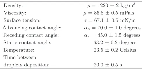
The properties of the coloured and uncoloured glycerol-water mixtures were measured and adjusted to produce a system with no interfacial gradients of den-sity, viscosity or surface tension. The fluid properties are shown in TableI.
Density: ρ= 1220±2 kg/m3
Viscosity: µ= 85.8±0.5 mPa.s
Surface tension: σ= 67.1±0.5 mN/m
Advancing contact angle: αa= 70.0±1.0 degrees
Receding contact angle: αr= 45.0±1.5 degrees
Static contact angle: 63.2±0.2 degrees
Temperature: 23.5±0.2 Celsius
Time between
[image:3.595.320.564.400.519.2]droplets deposition: 20.0±0.5 s
TABLE I: Fluid and droplet properties for coloured and un-coloured mixtures.
±0.5 mPa s), to a 100 ml sample of the uncoloured so-lution. Pure water was then added to the dyed solution until the viscosities of the coloured and uncoloured fluids were matched.
The liquid-substrate interaction was characterised by the measurement of the equilibrium contact angle and the contact angle hysteresis, using a similar method to that in [29]. A shadowgraph system was used to illuminate, from behind, sessile droplets resting on a substrate mounted on a rotational stage. Equilibrium contact angles were imaged with the substrate horizontal. Receding (αr) and advancing (αa) contact angles were recorded by tilting the substrate up to the first point of slip; an example of this is shown in Fig. 2. From the image analysis of these recordings, the contact angles were calculated by linear and polynomial fitting. The same methodology was used on both fluid solutions (coloured and uncoloured). No difference, within experimental error, was observed in the contact angles for the coloured and uncoloured droplets.
Experimental profile Lattice Boltzmann simulation
FIG. 2: (Colour online) Contact angle hysteresis analysis showing advancing and receding contact angles of a drop on an inclined PMMA surface just starting to slip. The image shows a comparison of experimental measurement and nu-merical modelling of an uncoloured mixture of glycerine and water with a viscosity of 85.8 mPa s. The droplet starts to slip when the surface is inclined at approximately 25◦.
III. SIMULATION METHOD
Reliable, predictive simulations of droplet impact and coalescence could provide a useful tool to complement experimental visualisation, allowing access to pressure fields, fluid flow trajectories and other data that is diffi-cult to obtain experimentally. However, modelling flows with moving contact lines, particularly in 3D, is very challenging. In addition to the computational resource issue associated with capturing 3D time-dependent flow, the crucial difficulty with most simulation methods, for example the popular volume-of-fluid (VoF) approach, is that the dynamic contact angle needs to be prescribed, often in a complicated fashion [30–33] dependent on ex-perimental measurements. Simulations of flows such as the impact and spreading of droplets are particularly sen-sitive to the dynamic contact angle behaviour. Yokoi et al. [33] found that accurate dynamics could only be achieved when using a dynamic contact angle based on experimental observations.
In contrast, the lattice Boltzmann method used here does not require the dynamic contact angle to be speci-fied. Instead, the wetting characteristics of the solid sur-face are included only through the static contact angle, and the dynamic behaviour emerges during the simula-tion. This makes the method particularly suitable for the asymmetric, fully three-dimensional coalescence configu-ration considered here, since the dynamic contact angle varies continuously around the whole perimeter defined by the contact line. Of course real surfaces do not in gen-eral exhibit a unique static contact angle; indeed contact angle hysteresis plays an important role in determining the final composite droplet footprint. Hence the model used here includes hysteresis and its inputs are only the advancing and receding static contact angles rather than the dynamic contact angle that varies widely and must be specified at all points along the contact line (as in VoF). In this work, the static contact angles were measured ex-perimentally by using a tilted substrate, as described in
§II. Once calibrated by simulating this experimental ar-rangement to produce the correct angles (see Fig.2), the model is used without any further adjustment to simulate the droplet impact and coalescence.
Rather than solving the Navier-Stokes equations by conventional direct discretisation of the partial differen-tial equations, the LB approach is based on a velocity space discretisation of the Boltzmann equation in which molecular velocities are represented by a set of (typically in 3D) 19 microscopic velocities,~ea (a= 0, . . . ,18). The ~eaare given by the zero vector and the vectors connecting each node to its 18 nearest neighbours in a cubic lattice structure, and each has associated with it a probability distribution function,fa. The macroscopic fluid density, ρ, and velocity, ~u, at each lattice node are found from moments of the distribution functions:
ρ= 18 X
a=0
fa and ρ~u= 18 X
a=0
fa~ea. (1)
The dynamics of the flow emerge as the values of fa across the whole lattice evolve following a two-step pro-cess at each time step: (i) relaxation towards a local Maxwellian equilibrium distribution, capturing the effect of molecular collisions, and (ii) ‘streaming’, in which the value of eachfa moves along its associated vector to the neighbouring node. Using a single relaxation time, τ, which is related to the fluid kinematic viscosity, the pro-cess can be written as
fa(~x+~ea, t+ ∆t) =fa(~x, t)−
[fa(~x, t)−faeq(~x, t)]
τ (2)
where the local Maxwellian equilibrium distribution is given by:
feq
a (~x, t) =waρ
1 + 3~ea·~u c2 +
9 2
(~ea·~u)2
c4 −
3 2
~u2 c2
(3)
[image:4.595.54.303.284.363.2]Series: 1 2 3
Impacting droplet radius (r0): 1.39 ±0.05 mm 1.20 ±0.05 mm 1.19 ±0.05 mm
Initial radius of sessile droplet: 1.40 ±0.05 mm 1.30 ±0.05 mm 1.52 ±0.05 mm
Impacting droplet speed (v): 1.12±0.04 m/s 1.08±0.04 m/s 2.23±0.08 m/s
Dimensionless time factor (2r0/v): 2.48±0.18 ms 2.22±0.17 ms 1.07±0.08 ms
[image:5.595.62.558.175.488.2]Dimensionless time for maximum spreading: 1.6±0.3 1.8±0.4 2.8±1.2
TABLE II: Experimental conditions explored in this work.
FIG. 3: (Colour online) Colour high-speed imaging of the impact and coalescence of an uncoloured sessile and an impacting coloured droplet. In these experiments, the impact speed is 1.12±0.04 m/s (Series 1 in TableII).
time, ∆t the time step, and c the lattice speed. Us-ing a multiple scale analysis, it can be shown that the Navier-Stokes equations can be obtained from the lattice Boltzmann equation [34].
There are various means of modelling multiphase flow using the LB framework, e.g. [35–37]. In this work the Shan-Chen [38] model is used since it was found to give the closest qualitative agreement with the free-surface shapes seen in the experiments. This efficient model introduces an interaction potential between neighboring lattice nodes, which can be expressed as:
F(~x, t) =−Gψ(~x, t) 18 X
a=0
waψ(~x+~ea, t)~ea (4)
whereFis fluid-fluid interaction force,Gis an interaction
strength parameter (negative for particle attraction), and ψis a potential function that depends on density:
ψ(ρ) =ρ0[1−exp(−ρ/ρ0)] (5)
where ρ0 = 1. This model produces a non-ideal equa-tion of state supporting the coexistence of a heavy phase of density ρh and a light phase of density ρl. However, use of this equation of state limits the density ratio be-tween the heavy and light phases to about 100 and re-sults in large spurious currents at the liquid-gas interface that hamper the tracking of passive tracer particles in this region. Here, following previous work [39, 40], the Carnahan-Starling equation of state
p=ρRT1 +bρ/4 + (bρ/4) 2
−(bρ/4)3 (1−bρ/4)3 −aρ
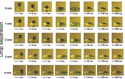
FIG. 4: (Colour online) Colour high-speed imaging of the impact and coalescence of an uncoloured sessile droplet and an impacting coloured droplet. These experiments corresponds to series 2, in which the sessile and the impacting droplet have a different volume.
is used (with parameters a = 1, b = 4 and R = 1) to extend the density ratio to 525 (G = −0.0553, ρh = 0.43112, ρl= 0.0008196668) and reduce the spurious cur-rents at interface while keeping the simulation stable.
Further increase of the density ratio led to instabilities and simulation failure, but further increase was deemed unnecessary since the simulation predictions were insen-sitive to density ratio at ρh/ρl = 525. Two relaxation times, τh = 1.0 and τl = 0.6, for the heavy and light phases respectively, are used to capture the different vis-cosities of the phases, and a linear interpolation based on local density value is used to calculate the relaxation time locally at every lattice node. Setting the lattice spacing atdx= 6.071×10⁻⁵
m and time step asdt= 4.0×10⁻⁵ s produces a kinematic viscosity ratio ofνh/νl= 4.741.
The wetting characteristics of the substrate are incor-porated by specifying an artificial fluid density,ρs, at the solid surface, such thatρl≤ρs ≤ρh [41,42]. This pro-duces an equilibrium contact angle between zero and 180◦ measured through the heavy phase. For convenience the surface density is defined in terms of a normalised ‘wet-ting parameter’,
η= ρs−ρl ρh−ρl
, (7)
so that η = 1 corresponds to equilibrium angle αe = 0◦ andη= 0 toαe= 180◦. Such specification of an artificial fluid density at the solid wall will generate an adhesion force at the solid-fluid interface through the multiphase model (4).
Inclusion of contact angle hysteresis is essential for cor-rect modelling of the dynamics of impacting and coales-cencing droplets [14], and hysteresis is included here us-ing a similar method to that in Ref. [14]. Initially, the value of η = 0.44 on the unwetted solid surface is set to correspond to an equilibrium angle equal to the ad-vancing static contact angle, αa, found experimentally. Parts of the surface that become wetted then have their value of η = 0.61 modified to correspond to the experi-mentally determined receding contact angle. Making the change inη over a controllable time scale also allows the effects of surface adhesion saturation times [43] to be in-corporated. When a wetted part of the surface is dewet-ted, the surface density returns to its original (advancing contact angle) value over a controllable time scale. Since ρl≤ρs≤ρh, the wetted/unwetted parts of the solid sur-face can be identified by the gradient of density normal to the surface, with∂ρ/∂n >0 corresponding to a wetted patch and∂ρ/∂n <0 to an unwetted part.
[image:6.595.64.546.46.298.2]D
ro
p
S
e
p
a
ra
ti
o
n
t = -2 ms t = 0 ms t = 10 ms t = 20 ms t = 100 ms t = 500 ms
3 mm 2 mm 1 mm 0 mm
4 mm
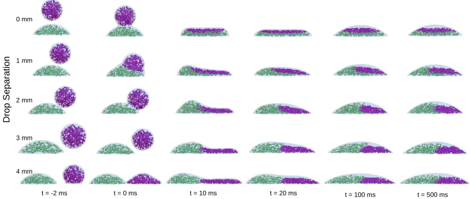
FIG. 5: (Colour online) Internal flow analysis of sessile and impacting droplet during spreading phase using lattice Boltzmann simulations. The configuration corresponds to experimental Series 2.
IV. RESULTS
Three series of experiments were carried out to ex-plore the coalescence and mixing under various dynami-cal regimes. Lateral drop separation, drop size and im-pacting speed were varied within the capabilities of the system. Only conditions which produced single droplets from the generators were used. TableIIsummarizes the details of these experiments.
Under these conditions, the system can be dynami-cally characterized by the Reynolds (Re =ρr0v/µ), We-ber (We = ρr0v2/σ) and Ohnesorge (Oh =
√
We/Re) numbers of the impacting droplet. Experimentally these numbers lie in the following ranges: Re=20–23, We=29– 33 and Oh=0.25–0.26. These dimensionless numbers were chosen to lie within the operating parameters found in most commercially available inkjet printers, e.g. for typical inkjet printing systemsρ≈1,000 kg/m3
,r0≈50 µm, v = 5 m/s, µ = 10 mPa s and σ = 45 mN/m. It has been demonstrated that the behaviour of impact-ing droplets of different size and temporal scales can be compared using the dimensionless time to reach the max-imum spreading diameter and by scaling the time by 2r0/v, [44]. These scaling parameters are shown in Table
IIto facilitate the comparison with other systems. In addition to variation of the drop size and speed, the droplet separation was varied from axisymmetric impact conditions (i.e. zero separation) up to a lateral separation of 4 mm from drop center to drop center.
A. Internal views of equal-size droplets merging
Fig. 3 presents experimental images of a coloured droplet impacting at 1.12±0.04 m/s on to an uncoloured
sessile droplet. Time t = 0 is taken to be the moment of first contact of the droplets. The first sequence corre-sponds to the axisymmetric case, where the centre of the impacting droplet lies directly above that of the sessile droplet. As can be seen, the impact produces a large dis-turbance to the free surface as the combined droplet flat-tens and spreads out into a pancake shape. Att= 5 ms spreading of the combined droplet has reached its full extent, and at this point the coloured and uncoloured parts appear to have been completely mixed. However, this is not the case, as later frames show the recoil of the free surface and reveal that no intermixing of the ini-tial droplets has occurred. The substanini-tial disturbance to the free surface clearly produces a stretching of the ‘interface’ between the coloured and uncoloured regions, but crucially there is no folding of this interface upon itself. Repeated stretching and folding of the interface is the basis for mixing enhancement via chaotic advec-tion. Without folding of this interface, when the com-bined droplet recoils the interface shrinks again to reach the final lens-like shape of the larger sessile droplet. At much later times, molecular diffusion drives a slow inter-mixing of the coloured and uncoloured parts.
[image:7.595.63.547.54.259.2]FIG. 6: (Colour online) Colour high-speed imaging of the impact and coalescence of an uncoloured sessile droplet and an impacting coloured droplet. These experiments corresponds to Series 3 in which the impacting droplet has approximately twice the speed of the one in Series 1.
combined droplet (for example by a wettability gradient [23]) while the impacting droplet spreads above it, then folding of the interface between the droplets could occur. Under the dynamic conditions and offset alignment of these experiments, the collision of two free droplets would produce a degree of mixing within the combined droplet [17] as it spins, stretches and oscillates due to the asym-metric contact. Here, the presence of the substrate in-hibits this motion, and the deformation of the free sur-face is further restricted by the dynamics of the moving contact line. Hence there remains a sharp interface be-tween the dyed and undyed liquids and no mass transfer between the original droplets.
In all cases the final combined droplet shape is the same as that obtained without colouring the impacting droplet. Also as expected, increasing the droplet sepa-ration results in the coloured part of the final, combined droplet being located further to the right.
The droplet separation of 4 mm (lowest row of images) approaches the maximum separation at which coales-cence is still possible. Under these conditions the dis-turbance of the sessile droplet is small, apart from the formation of the neck between the droplets, as in the coalescence of two sessile droplets. It is therefore not surprising to see the coloured and uncoloured parts of the droplet remaining separate.
The lack of mixing during droplet impact and coa-lescence is beneficial for graphical printing applications where good colour separation is required. However this could be problematic for applications where the mixing of components or colour is desired — particularly for droplet-based chemistry [45], where good mixing is es-sential. The observations here indicate that under the conditions explored homogeneous mixing is not achieved by drop deposition and coalescence. Future work on this topic could include the parametric study of droplet
mix-ing in terms of liquid and substrate properties to assess under which conditions the conclusions drawn by Kr¨ober et al. are appropriate [15]. However, from the observa-tions in this work, it is important to note that having only a top view of drop-on-drop deposition is not enough to evaluate mixing and that a side-view is necessary.
B. Coalescence of different-sized droplets
Fig.4shows a second series of experiments in which the impacting droplet volume is a little smaller than that of the sessile droplet (Series 2 in TableII). The impact speed is nominally the same as in Fig.3. The images show that the behaviour is qualitatively the same as for equal-sized droplets, and again no folding of the ‘interface’ between the coloured and uncoloured liquids is seen. The side-view imaging proved to be invaluable as use of a top view would wrongly suggest that mixing was achieved.
t = 0 t = 6 ms
t = 660 ms t = 920 ms t = 1440 ms
t = 18 ms
FIG. 7: (Colour online) Numerical simulation showing vortex ring generation when a small droplet impacts on a sufficiently large sessile droplet.
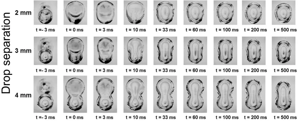
[image:8.595.65.548.50.239.2] [image:8.595.318.564.550.652.2]visual-FIG. 8: High-speed imaging of the impact and coalescence of an uncoloured sessile droplet and an impacting coloured droplet. Images are taken from underneath the substrate by oblique illumination. In these experiments, the impacting speed is of 1.12
±0.04 m/s. Images have been colour-inverted to show the contact line and shapes more clearly.
isation produced by the lattice Boltzmann simulations (see Fig.5), where the passive tracers remain separated. The simulations show good qualitative agreement with the experiments in terms of the internal and external dy-namics, though there is a small discrepancy in the time. Such temporal discrepancies have been observed before [46] and arise as a result of the computational liquid-gas interface thickness being larger than in practice. At later times in the simulations, as the droplet begins to recoil, the surface of the impacting droplet stops moving down-wards and begins to move updown-wards. During this change of direction, the normal velocity of the liquid-gas inter-face is very small and spurious currents in the liquid-gas interface that are normally negligible compared to the average fluid velocity result in a small displacement of the tracer particles away from the interface. As the in-terface then accelerates upwards, a small region adjacent to the interface is left devoid of tracers. Tracers in the bulk of the combined droplets are unaffected.
If the size of the impacting droplet is reduced signif-icantly further, it is possible to reach conditions under which a vortex ring is generated when the small droplet is pulled into the larger one. This is illustrated by the nu-merical simulation in Fig.7, which shows the first stages. This effect is well known [16], and produces an extended ‘interface’ between the two bodies of liquid, thus assist-ing later diffusion-driven mixassist-ing of the two droplets at least in part of the composite droplet. However, the ef-fect soon dissipates and again produces no active stretch-ing and foldstretch-ing of the outer boundary of the coloured ‘blob’. This mechanism is relevant to the experiments of Fathi & Dickens [7] where small drops of a second reagent are deposited on a large drop of another reagent (which was built up by printing multiple small droplets), and supports their conclusion that their reagents are mixed. However, the results of Figs. 3 and 4 indicate that,
un-der the conditions used in the present experiments, if reagents are combined via individual drop-on-drop depo-sition, then mixing will be very poor.
Fig.6 shows the side view of further experimental se-quences in which the impact speed is approximately dou-bled. Here, the disturbance of the free surface during coalescence is correspondingly more violent. In particu-lar, att≈3 ms the coloured liquid lamella almost spills over the left-hand side of the uncoloured liquid. Such a spillover could result in the entrainment of a finger of uncoloured liquid into the coloured liquid, hence fold-ing over the ‘interface’ between these two regions. How-ever, increasing the speed further to achieve this effect is likely to promote splashing and loss of control of the com-posite droplet footprint, which in a printing application would be undesirable. As can be seen in Fig.6, despite the increased free-surface distortion during coalescence, the end result is a composite droplet incorporating two separate volumes of liquid corresponding to the initial droplets.
C. Evolution of droplet contact area
As outlined above, the experimental arrangement al-lows for a simultaneous view of the coalescence process from underneath. This is particularly useful for explor-ing the final footprint of the composite droplet, which is important in manufacturing applications where a contin-uous printed track is desirable.
[image:9.595.63.550.53.251.2]t = -5 t = 0 ms t = 9 ms t=27 ms t = 100 ms t =400 ms t = 500 ms
D
ro
p
s
se
p
a
ra
ti
o
n
4
m
m
t = -5 t = 0 ms t = 9 ms t=27 ms t = 100 ms t =200 ms t = 500 ms
D
ro
p
s
se
p
a
ra
ti
o
n
4
m
m
Static contact angle α= 57.5º
Lattice Boltzmann method with hysteresis model Contact angles: advancing (α
a= 70º) and receding (αr= 45º)
FIG. 9: (Colour online) Evolution of the dynamic contact line modelled by lattice Boltzmann method without (upper sequence) and with (lower sequence) contact angle hysteresis model. The configuration corresponds to Series 2.
of the composite droplet and the expansion of the ‘neck’ region when the initial droplet separation is large. The elongated shape of the composite droplet further illus-trates the damping effect that the substrate has on the free surface movement and hence the scope for mixing within the combined droplet.
To illustrate the importance of capturing contact an-gle hysteresis correctly, Fig.9shows the evolution of the droplet footprint predicted by the simulation with and without contact angle hysteresis. In the upper sequence, a single equilibrium contact angle is used, whose value is set to the average of the experimentally measured ad-vancing and receding contact angles, whereas in the lower sequence the correct advancing and receding angles are used. During the initial spreading phase of motion, there is little difference between the two sequences, though it can be seen that the neck width develops more slowly with hysteresis included. As the droplet reaches its max-imum extent and starts to retract, the effect of contact angle hysteresis is very apparent: without it, all com-posite droplets will eventually reach a circular footprint, whereas in practice the contact line becomes pinned. Note that the rightmost image in each sequence corre-sponds to the final state.
The sensitivity of the composite droplet footprint to the contact angle hysteresis makes this system a good test for the hysteresis model incorporated in the lattice Boltzmann simulations. Fig. 10 shows a comparison of the final footprints obtained experimentally and numer-ically with different droplet separations. As can be seen, excellent agreement is observed. Recall that in the lat-tice Boltzmann method used, the dynamic contact an-gle is not prescribed anywhere, and the surface wettabil-ity is accounted for only by the advancing and receding
static contact angles measured experimentally. There is no means of artificially pinning the contact line.
D = 2 mm D = 3 mm D = 4 mm
FIG. 10: (Colour online) Comparison of final footprints for different initial droplet separations. Red contours on the ex-perimental images (left) correspond to contours modelled by the lattice Boltzmann method (right). The configuration cor-responds to Series 2.
D. Dynamics of droplet coalescence on a surface with a wettability gradient
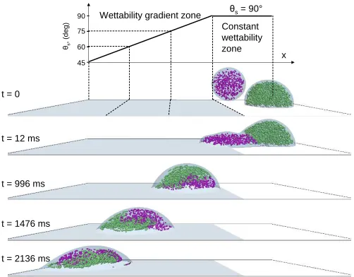
[image:10.595.129.481.49.282.2] [image:10.595.318.565.363.436.2]on a region of a solid surface having a uniform wettabil-ity (with static contact angle 90◦), but close to a region in which the static contact angle decreases linearly with distance. Rather than pushing the droplets together, as shown in [23], this gradient in wettability produces trans-port of the entire composite droplet.
θs
,
(d
e
g
)
θ
s= 90°
Wettability gradient zone
90
75
60
45
Constant wettability zone
t = 0
t = 12 ms
t = 996 ms
t = 1476 ms
t = 2136 ms
x
FIG. 11: (Colour online) Mixing within a composite droplet moving on a substrate with a wettability gradient. Time is given in lattice Boltzmann timesteps.
The impacting droplet lands on the boundary be-tween the regions of uniform and varying wettability, and spreads into the sessile droplet. Once coalescence of the two droplets has been initiated, the entire volume of the sessile droplet is rapidly dragged off the uniform region and on to the impacted droplet. The composite droplet dewets the uniform region, then travels along the sur-face with the wettability gradient, moving towards the more wettable area. As the composite droplet moves, the change in contact angle causes a continuous reduction in its aspect ratio. This creates a continuous variation in the flow field which promotes intermixing of the liquids from each droplet. This happens on a much shorter time scale that the slow coalescence observed by Laiet al. [23]. Re-cent experiments carried out elsewhere have shown that the speed at which the substrate is moving dictates the deposition dynamics and the onset of splashing (or lack thereof) [47]. As a consequence, the effect of a moving substrate on mixing dynamics is something that is yet to be studied. Another topic of future interest is that of chemical reactions within droplets; e.g. experiments where pH indicators or other reagents could be added to the droplet or the substrate in order to monitor the progress of a chemical reaction or the extent of spread-ing and pinnspread-ing of the contact line on chemically treated substrates.
V. CONCLUSIONS
Despite the large free-surface deformations that arise in the impact and coalescence process, no mixing of the two droplets occurs for the conditions explored here, which are dynamically equivalent to the conditions typi-cal of drop-on-demand inkjet printing. The impact and coalescence happen on a time scale much shorter than that of diffusion, and mixing can only be enhanced by advection if the ‘interface’ between the coloured and un-coloured liquids is stretched and folded to create fingers of liquid interpenetrating the original droplet volumes. Though rapid stretching of this ‘interface’ occurs dur-ing impact and coalescence, especially at small lateral droplet separations, it quickly contracts again without folding. Under these dynamic conditions, free droplets colliding asymmetrically can exhibit mixing in the com-bined drop due to the spinning, stretching and oscillation caused by the collision. However, the presence of a sub-strate inhibits much of this motion and prevents mixing. Furthermore, pinning of the contact line inhibits move-ment along the substrate.
The observations indicate that under conditions found in traditional inkjet technologies, the lack of mixing would clearly be problematic. A parametric study vary-ing liquid and substrate properties is required to iden-tify conditions of good and bad mixing for droplet-based chemistry applications.
Numerical simulations using the lattice Boltzmann method with the Shan-Chen multiphase model and a con-tact angle hysteresis model show good qualitative agree-ment with experiagree-ments in terms of the internal dynam-ics, and excellent quantitative agreement with the final printed footprint. The model is first calibrated by sim-ulating the experimental measurement of the advancing and receding contact angles, then used without further adjustment. A key feature of the model is that only these static contact angles are needed — the dynamic contact angle emerges from the simulation, without the need for complicated treatment. Simulations also reveal the ap-pearance of the well-known vortex ring when the impact-ing droplet is sufficiently small compared with the sessile droplet. Finally, simulations show that, when a surface wettability gradient is used to maintain movement and continuous extension of the composite droplet, mixing of the two liquids can be enhanced.
Acknowledgments
[image:11.595.53.304.150.346.2]References
[1] H. Sirringhaus,et al.,Science,290, 2129 (2003). [2] M. Sellier and E. Trelluyer,Biomicrofluidics,3, 022412
(2009).
[3] R.E. Saunders, J.E. Gougha and B. Derby,Biomaterials,
29, 193 (2008).
[4] H. Song,Anal. Chem.78(14), 4839 (2006).
[5] X. Yang, V.H. Chhasatia, J. Shah and Y. Sun,Soft Mat-ter,8, 9205 (2012).
[6] B. Derby,Annu. Rev. Mater. Res.40, 395 (2010). [7] S. Fathi and P. Dickens,J. Mater. Proc. Tech.,213, 84
(2013).
[8] H. Fujimoto, T. Ogino, H. Takuda and N. Hatta,Int. J. Multiphase Flow27, 1227 (2001).
[9] H. Fujimoto, A.Y. Tong and H. Takuda,Int. J. Thermal Sci.47, 229 (2008).
[10] R. Li, N. Ashgriz, S. Chandra, J.R. Andrews and J. Williams,J. Manuf. Sci. Eng.,130, 041011 (2008). [11] R. Li, N. Ashgriz, S. Chandra, J.R. Andrews and S.
Drap-pel,Exp. Fluids,48, 1025 (2010).
[12] W. Lee and G. Son,Comput. Fluids,42, 26 (2011). [13] X. Yang, V.H. Chhasatia and Y. Sun,Langmuir,29, 2185
(2013).
[14] J.R. Castrej´on-Pita, E.S. Betton, K.J. Kubiak, M.C.T. Wilson and I.M. Hutchings,Biomicrofluidics 5, 014112 (2011).
[15] P. Kr¨ober, J. T. Delaney, J. Perelaer and U.S. Schubert,
J. Mater. Chem.19, 5234 (2009)
[16] A.V. Anilkumar, C.P. Lee and T.G. Wang,Phys. Fluids
A11, 2587 (1991).
[17] N. Ashgriz and J. Y. Poo, Journal of Fluid Mechanics 221, 183-204 (1990).
[18] J.J. Thomson and H.F. Newall,Proc. Roy. Soc. London 39, 417 (1885).
[19] L. V. Zhang, J. Toole, K. Fezzaa and R.D. Deegan, J. Fluid Mech.690, 5 (2012).
[20] S.T. Thoroddsen,J. Fluid Mech.690, 1 (2012). [21] M-J. Thoraval, et. al, Phys. Rev. Lett. 108, 264506
(2012).
[22] A.A. Castrej´on-Pita, J.R. Castrej´on-Pita and I. M. Hutchings,Physical Review E 86, 045301 (2012). [23] Y. Lai, M. Hsu and J. Yang, Lab in a Chip, 10 3149
(2010).
[24] M.C.T. Wilson, J.L. Summers, N. Kapur and P.H. Gaskell,J. Fluid Mech. 565, 319 (2006).
[25] H. Song, J.D. Tice, R.F. Ismagilov, Andew. Chem. Int. Ed. 42, 767 (2003).
[26] C.-P. Lee, H.-C. Chen and M.-F. Lai,Biomicrofluidics6,
012814 (2012).
[27] J.R. Castrej´on-Pita, G.D. Martin, S.D. Hoath and I.M. Hutchings,Rev. Sci. Instrm.79, 075108 (2008). [28] J.R. Castrej´on-Pita, N.F. Morrison, O.G. Harlen, G.D.
Martin and I. M. Hutchings, Physical Review E 83, 036306 (2011).
[29] P.S. Yadav, P. Bahadur, R. Tadmor, K. Chaurasia and A. Leh,Langmuir 24, 3181 (2008).
[30] J. Fukai, Y. Shiiba, T. Yamamoto, O. Miyatake, D. Poulikakos, C.M. Megaridis and Z. Zhao, Phys. Fluids 7(2), 236 (1995).
[31] ˇS. ˇSikalo, H.-D. Wilhelm, I.V. Roisman, S. Jakirli´c and C. TropeaPhys. Fluids 17, 062103 (2005).
[32] I.V. Roisman, L. Opfer, C. Tropea, M. Raessi, J. Mostagmhimi and S. Chandra,Colloids Surf. A: Physic-ochem. Eng. Aspects322, 183 (2008).
[33] K. Yokoi, D. Vadillo, J. Hinch and I.M. Hutchings,Phys. Fluids,21, 072102 (2009).
[34] D.A. Wolf-Gladrow, Lattice-gas cellular automata and lattice Boltzmann models: an introduction, Springer, Berlin (2000).
[35] M. Liu, Z. Yu, T. Wang and L. Fan,Chemical Engineer-ing Science655615 (2010).
[36] T. Inamuro, T. Ogata, S. Tajima and N. Konishi,Journal of Computational Physics198628 (2004).
[37] H.W. Zhen, C. Shu and Y.T. Chewm,Journal of Com-putational Physics 218353 (2006).
[38] X. Shan and H. Chen,Phys. Rev. E,47, 1815 (1993). [39] X. He, S. Chen, R. Zhang, Journal of Computational
Physics 152, 642 (1999).
[40] P. Yuan, L. Schaefer,Phys. Fluids 18, 042101 (2006). [41] A.R. Davies, J.L. Summers and M.C.T. Wilson,Int. J.
Comp. Fluid Dyn.20(6), 415–425 (2006).
[42] D. Iwahara, H. Shinto, M. Miyahara and K. Higashitani,
Langmuir,19(21), 9086 (2003).
[43] R. Tadmor, K. Chaurasia, P.S. Yadav, A. Leh, P. Ba-hadur, L. Dang and W.R. Hoffer, Langmuir, 24, 9370 (2008).
[44] H. Dong, W.W. Carr and D.G. Bucknall,AIChE Journal 532606 (2007).
[45] P.J. Smith and A. Morrin, J. Mater. Chem.,22, 10965 (2012).
[46] J.M. Yeomans,Physica A369, 159 (2006).