Page 474 www.ijiras.com | Email: [email protected]
Comparative Study And Analysis Between Tunnel Formwork And
Conventioal Formwork System
Aditya S. Lahare
Post Graduate Student, Construction and Management, NDMVPKBT COE, Pune, Maharashtra, India
I. INTRODUCTION
Formwork includes the actual material contact with concrete known as form face and all the necessary associated supporting structure. Formwork should be capable of carrying all dead load and live loads on it. A detail construction planning is pre-requisite element to ensure the project in completing on time, planning and meeting the budget, quality, safe and environmental requirements. A well-organized and modern formwork requires less manpower and keeps costs in control. But substantially the client is a challenge and takes time.
Formwork planning is done as follows
STAGE 1: The necessary information and limiting conditions must be collected and defined. When projects of similar nature are executed, a checklist can be of immense help in obtaining information required to prepare a complete scheme.
STAGE 2: The formwork system to be used can be selected. In addition to cost of the materials, the choice of the system will be influenced by the experience of the planner and of the team, which has to set up the formwork on the site, and
by the project archive. A database / project archive that captures the experience gathered over the years can aid in cost effective system selection.
STAGE 3: This involves all engineering design tasks. This part of the process is most time consuming. It is important to be able to allow for changes arising at later phases of the project. The emphasis should be on maximum reuse of materials available and procuring minimum materials Just-In-Time.
II. OBJECTIVE
Objective of study is to study tunnel formwork systems & after to compare with Conventional system on basis on
Alternatives to reduce Slab cycle time
Productivity Analysis.
Cost Analysis.
And hence to suggest best formwork system for high rise building.
Abstract: India is developing country and it is in the process of going to more interconnected world. Now day’s duration, quality and cost are the main factors considered in construction; also as per current situation for more accuracy in work, industry should move from labour oriented to machine oriented. Recently lot of research is carried out in this sector, Tunnel formwork is a latest example of this modernization. Formwork selection is a main part in construction. Around 20-25% of construction cost is invested in formwork. To achieve quality and cost construction planning, material availability, customer requirements, limiting conditions are important. Advanced Tunnel formwork system is a highly systematic, earthquake resistant technique that produces monolithic structure in which slab, beam & walls are casted at one time which acts as RCC load bearing structure. This paper aimed at studying advanced tunnel formwork system in high rise building, to compare this system with Conventional system and to find best formwork in terms of economy and rapid construction.
Page 475 www.ijiras.com | Email: [email protected] III. FORMWORK
There are various types of formwork used in India. Several systems are adopted at different places in the world; eventually the systems which are reasonably economical and easy for operation with skilled labour are useful in India. Certain systems are in trend and more contractors are trying to bring in new technologies. Following are the types of formwork.
A. CONVENTIONAL FORMWORK
This is the oldest type of formwork used in the construction industry. This type uses timber, bamboo, masonry and carpentry in the construction. This type is very much suitable for small houses with two to three storeys and still they are in use for so many constructions.
B. MODERN CONVENTIONAL FORMWORK
In modern conventional formwork more advanced material is used and they can reuses several times. The differences of both types are that steel props and various types of jacks (U jack, T jack) are used instead of timber supports and ply wood sheets are used instead of timber planks on slab decks.eg. Cast in situ method of construction.
C. SEMI-SYSTEM FORMWORK
This type is much more advanced than the modern conventional type. In this type there are pre-fabricated formwork items such as pre-fabricated formworks for slab panels and supports and ply wood should be used additionally for slab deck, beams and columns for the surface. There are other forms of semi system formwork such as table forms, flying forms etc. DOKA is the most famous brand for this type of formwork and some people know about this type only as “DOKA formwork”. These types of formworks can be categorized under the Composite Construction method.
D. MODERN FORMWORK
System formwork has prefabricated modular components with casting panels. The system formwork is fabricated as it suits the required shape. The biggest advantage of this type is the speedy and quality construction. But the high initial cost is the main disadvantage and hence it is not economical to use in low–rise buildings. But this is the most economical form of formwork type to be used in high-rise building construction when it is having few typical storeys.eg. Mivan, Tunnel formwork
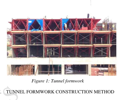
E. TUNNEL FORMWORK
The tunnel formwork is a room sized structural steel fabricated form which is used to cast the shear walls and floor slabs of a building as a monolithic structure in a continuous pour. The forms are then heated using hot air blowers for accelerated curing of the concrete for particular area. This is
the most cost-effective when the structure consists of large number of identical units.
The sequence of construction comprises placing of reinforcement, electrical and sanitary conduits along with the tunnel forms. Concrete is then poured and the open side of the forms is covered and hot air blowers placed inside. The forms are removed the next day and placed on the next site using cranes. The optimum use of tunnel form is in multiunit shear wall structure with identical floor layout at each level.
Figure 1: Tunnel formwork
F. TUNNEL FORMWORK CONSTRUCTION METHOD
a. TYPE & DESIGN OF THE STRUCTURE
The structure is designed as a portal frame having monolithic casting of the wall, slab and columns. The beams are eliminated and columns are in built with the wall.
b. FOUNDATION
The foundations are completed with the conventional method and dowels are left out for column and wall reinforcement. The wall reinforcement is tied in position along with the electrical conduits and reservations for the plumbing fixtures before placing the tunnel forms in position.
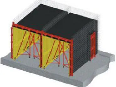
c. TUNNEL FORM WORK FOR WALL AND SLAB
Page 476 www.ijiras.com | Email: [email protected] Figure 2: Tunnel form work for wall and slab
d. SCAFFOLDING
For scaffolding & dismantling of the tunnel forms specially designed stripping platforms are used. This provides a readymade truss made with steel tube & having wooden scantling at top. Each bracket is composed of upper horizontal steel I beam of 120mm at least 6 meter long onto which three 60mm dia tubes are welded to form a triangular shape. These trusses are arranging d in the consoles between two successive slabs, already poured. This arrangement is very easy to install. The scaffolding arrangement requires no welding etc.& can be easily erected with tower cranes. The scaffolding for slab area of 100 Sq. m can easily be completed within 2 hours. The same scaffolding can be erected to next floor very easily with the help of crane.
e. REINFORCEMENT, PLUMBING RESERVATIONS & ELECTRICAL CONDUITS
The placing of the wall reinforcement leads the tunnel form work erection by one phase. To save the time reinforcement network are used in place of normal steel bars. Readymade prefabricated reinforcement mesh is used for slab & wall reinforcement. These meshes are available in different sizes & are cut in sizes as per drawing & placed in position with the help of cranes. This arrangement saves a lot of time in cutting, fabricating & placing the reinforcement. After placing the tunnels in position, reinforcement is placed in position. In accordance with the design, steel block outs may be installed on the form work panels to form the plumbing openings. Similarly the electrical conduits may be laid on the slab & in the wall before the concrete.
Figure 3: Reinforcement, plumbing reservations & electrical conduits
f. CONCRETING & HEAT CURING
After the completion of the formwork, concrete is poured. The grade of the concrete depends on the design. Normally concrete with 12 to 15mm slumps is used for walls & 7 to 9mm for the slab. After completion of the concrete the tunnels are closed with protective curtains to assist the curing process. Sealing the ends of the curing tunnel and heating the enclosed space from inside with the help of burners & LPG are used to heat the concrete. The slab is covered from top with an insulating material to prevent the heat loss. This process shall continue till the concrete attains the desired strength. However care is to be taken to prevent concrete from burning. The studies show that the concrete attains maximum strength in 12 hours, when heated up to 54 degree C. Care must be taken that the internal temperature of the concrete should not exceed 80 degree C. The rate of the temperature rise should be limited to 20 degree C. /Hours. Before any heat is applied, minimum procuring period of 2 hours is recommended. This process normally takes 6 to 12 hours depending on the weather conditions.
Figure 4: Concreting & heat curing
g. QUALITY CONTROL OF THE CONCRETE
Concrete cubes are taken at the time of the concreting as per the normal procedure. To confirm that the strength required for striking has been achieved, cubes should be cured under the insulation on the upper central area of the slab and then tested before the form is struck. The cubes should follow the same temperature history of the concrete in the slab as closely as possible, if they are to reflect the maturity of the slab. If the strength of the cube is around 65 to 70% of the designed strength, the stripping process may start.
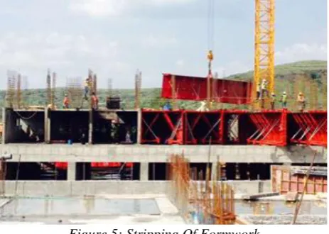
h. STRIPPING OF THE FORMWORK
Page 477 www.ijiras.com | Email: [email protected] location. All spacer cones are removed from the wall by
means of a punch.
Figure 5: Stripping Of Formwork
IV. CASE STUDY
Sr.
No. Details Case study I Case study II
1 Name of firm
Rohan Builders India Pvt. Ltd, Pune
A V Bhat builder, Pune
2 Name of project
Rohan Abhilasha Wagholi, Pune
Ectsasia, Hingane, Pune
3 Type of project Residential Residential
4 Type of system used TUNNEL formwork
Conventional system
5
Area for data
collection Wing A6 of ,'A' block Ecstasia
6
Consultant hired for system
MESA Imalat,Hi Tek Insat
Navate Architct, JW
consultant 7 Slab Area 13568 sq. meter 3345sq. m.
Table 1: Table summarizing case studies
V. DATA COLLECTION
Data collected from both site is as below:
Plan, Section of building
Survey report
Quantity estimates of material (Steel, Concrete & formwork)
Formwork technical manuals & user guide.
On site actual data collection.
VI. DATA ANALYSIS FROM STUDY
From bar chart prepared based on data collected there are 3 possible alternatives where we can reduce time in each slab cycle.
Concreting operations.
Crane operation.
By increasing quantity of formwork.
Increase in labour productivity.
ALTERNATIVE 1: REDUCING TIME IN CONCRETING OPERATIONS
Average rate of concreting operation with transit mixer is 15 m3 per hour. This quantity can be increased by supplying concrete direct from batching plant to concreting area. Average distance of pipeline is 105 meter from batching plant to concreting area. This alternative is not possible due to following reasons.
Due to added hyper plasticizers setting time of concrete is reduced as per demand of site engineers to achieve slab cycle of 4 days.
Due to longer pipeline (about 110 meter) chances of setting of concrete in pipeline itself leads to choke up problem with concrete pump.
Also direct supply of concrete from batching plant to concreting area leads to segregation of concrete due to difference between batching plant output and concrete pump capacity.
These problems can be overcome by using 2 transit mixers for concreting activity.
ALTERNATIVE 2: REDUCING TIME IN CRANE OPERATION
Second alternative available is reducing time by optimizing tower crane operations. From bar chart drawn it is clear that tower crane remain idle for 2 hours every day. This time can be used for activities in next day, but as all activities are to be carried out in continuous manner we cannot reduce time by using tower crane for next day activity. However we can use this time to carry out other works such as moving material to store, moving material from store to required position etc.
ALTERNATIVE 3: INCREASE QUANTITY OF
SHUTTERS
At present 50 % of quantity per floor is being used Increasing quantum of shutters can be one of the alternative but it leads to subsequent increase in heavy machinery, highly skilled labour and initial investment.
tunnel formwork if used 100% quantum of slab, as it involve heavy investment in procurement, heavy machineries, specialized expert labour it becomes uneconomical. In case project involves more than 20 storied building over large area, total economics may change considerably. However this aspect will require further study to arrive at conclusion.
ALTERNATIVE 4: INCREASE IN LABOUR
PRODUCTIVITY
Page 478 www.ijiras.com | Email: [email protected] CYCLE TIME ANALYSIS (TUNNEL FORMWORK)
For cycle time analysis of tunnel formwork, slab cycle of both systems is studied and based on average cycle time of both systems i.e. 4days slab cycle of tunnel formwork and 20 days slab cycle of conventional system study is done.
Following chart is prepared by combining average slab cycle of slab and tower crane data collected from site.
Area considerations
Formwork available: Formwork available (1500 m2)
Concrete area of building A6-I for slab & wall (Tunnel formwork area required):1480 m2
Slab area per floor of building A6 part I : 550 m2 Time considerations
Time required taking out “one half tunnel”, moving to desired location and fixing to location is 8 minutes.
Time required unfixing “wooden platform”, and moving it to desired location and then fixing is 20 minutes.
Time required to move and fix “wall/ slab box out” is 6 min.
PRODUCTIVITY ANALYSIS
A production rate is defined as the number of units of work produced by a person in a specified time. Production rates may also specify the time in man-hours or man-days required to produce a specified number of units of work. The time that a labour will consume in performing a unit of work varies between labours and between projects and with climatic conditions, job supervision, complexities of the operation and other factors. Productivity is one of the factors in time & cost calculations. More is the productivity less will be time required for activities and hence cost. Work done in one day (in m2) Total man hours
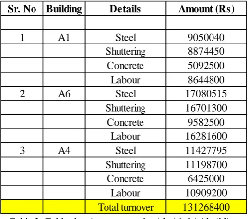
COST ANALYSIS
Sr. No
Building
Details
Amount (Rs)
1
A1
Steel
9050040
Shuttering
8874450
Concrete
5092500
Labour
8644800
2
A6
Steel
17080515
Shuttering
16701300
Concrete
9582500
Labour
16281600
3
A4
Steel
11427795
Shuttering
11198700
Concrete
6425000
Labour
10909200
Total turnover
131268400
Table 2: Table showing turnover for A1, A6 &A4 building (Constructed by using 1 set of tunnel formwork)
Sr. No Description Quantity Unit Rate (Rs/ Unit) Amount (Rs)
1 RCC work
A Footing, Plinth beam (M25) 250 4300 1075000
B 1st to 3rd floor (M30) 950.72 4500 4278240
C 4th to 7th floor (M30) 950.72 4500 4278240
D Terrace floor 179.32 4025 721763
Total concrete (M 20, M 25, M30) 2330.76 RS 10353243
2 Reinforcement (3% wastage)
A 1st to 14 th floor 469 46000 21574000
B Terrace floor 11 46000 506000
C Binding wire 11.21 50000 556050
Total reinforcement RS 22636050
3 Conventional material
Ply 1100 no 1200 1320000
Ballies 2000 no 200 400000
Wooden planks 500 Sq. Meter 1500 750000
Total material RS 2470000
4 Labour
Fitter 3345 Sq. Meter 32 107040
Shuttering labour 3345 Sq. Meter 40 133800
Concreting labour 2330 Cu. Meter 225 524250
Total Labour RS 765090
Total amount RS 36224383
Cu. Meter
MT
Table 3: Table showing part BOQ of RCC work slabs for Residential building Ecstaisa site
VII. CONCLUSION
Real estate construction industry has a reputation of not begin very technologically sophisticated, generally lagging in innovation, construction techniques & management. But now a day’s lot of research is carried out in this sector, advanced Tunnel formwork is good examples of this innovation.
We can achieve 1-3 days slab cycle by TUNNEL formwork system, where as we also can use Conventional formwork we can achieve slab cycle of 21 days.
Considering Indian conditions tunnel formwork if used 100% quantum of slab, as it involve heavy investment in procurement, heavy machineries, specialized expert labour it becomes uneconomical. In case project involves more than 20 storied building over large area, total economics may change considerably.
Also after studying and comparing both the systems it can be concluded that, though initial investment and per day operational cost in Tunnel formwork is more than Conventional system, due to more reuses and reduced slab cycle time Tunnel formwork works out ultimately economical.
Returns from initial investment regained due rapid completion of project Hence in long term consideration Tunnel formwork system is beneficial than that of Conventional formwork system.
ACKNOWLEDGEMENT
Page 479 www.ijiras.com | Email: [email protected] REFERENCES
[1] Meriam Webster Defines formwork(SICETE) 27
[2] Karke Swapnali M , Kumathekar M.B.Comparison of the use of Traditional and Modern Formwork Systems [3] Kazi1 Arbaz, Parkar Fauwaz Comparative Study And
Decision Making For A Formwork Technique To Be Adopted On A Construction Site In Mumbai
[4] Ninjal M Parekh, Bhupendra M Marvadi, Umang Patel, comparative studies of construction Techniques (conventional technique vs. Aluminium Formwork techniques), journal of information, knowledge and research in Civil engineering,
[5] Patil Dhanashri Suryakant and Prof. Desai D B, “Emerging Trends in Formwork - Cost Analysis & Effectiveness of Mivan Formwork over the Conventional Formwork” IOSR Journal of Mechanical and Civil Engineering (IOSR-JMCE) ISSN: 2278-1684, PP: 27-30 www.iosrjournals.org. Second International Conference on Emerging Trends in Engineering (SICETE) 27 | Page Dr.J.J.Magdum College of Engineering, Jaysingpur. [6] S. A. Anuar, N. H. Hamid, M. H. Hashim, S. M. D.
Salleh, “Comparison of Double Unit Tunnel Form Building before and after Repair and Retrofit under in-Plane Cyclic Loading”, World Academy of Science, Engineering and Technology, International Journal of Civil, Environmental, Structural, Construction and Architectural Engineering Vol:8, No:12, 2014.
[7] Dilek Tezgelen and Ozgul Yilmaz Karaman, “Evaluation of user comfort in tunnel formwork housing: Izmir as a Case Study”, Archnet-IJAR, International Journal of Architectural Research 2014.
[8] Yaser Sotoudeh, MozhdehSalehi, SaeedMoradzadeh, HomayoonTaghipoor, Meisam Behboodi, Building technology for mass concrete tunnel form method”,
Advances in Environmental Biology, 7(9): 2190-2194, 2013 ISSN 1995-0756.
[9] Sandip.P.Pawar and P.M.Atterde, “Comparative analysis of formwork in multistory building”, IJRET: International Journal of Research in Engineering and Technology, Volume: 03 Special Issue: 09, June-2014.
[10] Taehoon Kim, Hunhee Cho*, and Kyung-In Kang “Form work management based on ubiquitous computing for high-rise building construction”, School of Civil, Environmental and Architectural Engineering, Korea University, Seoul, Korea.
[11] Hisham A. Abou Ibrahimand Farook R. Hamzeh, “Role of formwork systems in high-rise construction” 5th International/11th Construction Specialty Conference 5eInternational/11e Conférence spécialiséesur la construction Vancouver, British Columbia June 8 to June 10, 2015.
[12] Sameer S. Malvankar, “Factors Affecting the Selection, Economics Involved in Formwork” The master builder, July 2013, www.masterbuilder.co.in
[13] Name of the author: Ramesh Kannan.M, Helen Santhi.M, “Constructability Assessment of Climbing Formwork Systems Using Building Information Modelling”, Science direct, Procedia Engineering 64 (2013) 1129 – 1138. [14] Prathul U, Leeladhar Pammar, Analysis of Productivity
by Comparing Mivan and Conventional Formwork, Journal of Emerging Technologies and Innovative Research (JETIR -ISSN-2349- 5162) (ww.jetir.org), April 2015, Volume 2, Issue 4. List of miscellaneous literature (Handbooks & user manuals)
[15] Dunne group ltd. Cellular construction using tunnel form, Dunne Group Ltd Tunnel Form 2009