Four Quadrant Speed Control of DC Motor with
the Help of AT89S52 Microcontroller
Vikash Kumar Rekha Jha
M. Tech Student Assistant Professor
Department of Electrical Engineering Department of Electrical Engineering BIT Sindri, Jharkhand,
India
BIT Sindri, Jharkhand, India
Abstract
Speed control of a machine is the most vital and important part in any industrial organization. This paper is designed to develop a four quadrant speed control system for a DC motor using microcontroller. The motor is operated in four quadrants i.e. clockwise, counter clock-wise, forward brake and reverse brake. It also has a feature of speed control. The four quadrant operation of the dc motor is best suited for industries where motors are used and as per requirement they can rotate in clockwise, counter-clockwise and also apply brakes immediately in both the directions. In case of a specific operation in industrial environment, the motor needs to be stopped immediately. In such scenario, this proposed system is very apt as forward brake and reverse brake are its integral features. Instantaneous brake in both the directions happens as a result of applying a reverse voltage across the running motor for a brief period and the speed control of the motor can be achieved with the PWM pulses generated by the microcontroller. The microcontroller used in this project is from 8051 family. Push buttons are provided for the operation of the motor which are interfaced to the microcontroller that provides an input signal to it and controls the speed of the motor through a motor driver IC. The speed and direction of DC motor has been observed on digital CRO. Microcontroller programming has been written in assembly language by using notepad and it has been converted in hex file by using micro vision Kiel. The burning of programming in the 8051 microcontroller chip has been done by using positron boot loader software.
Keywords: DC motor, AT89S52 Microcontroller, Motor Driver (L293D), Voltage Regulator (LM7805), Push Buttons, PWM.
_______________________________________________________________________________________________________
I.
I
NTRODUCTIONDC machines play a very important role in industries and in our daily life. The outstanding advantage of DC machines is that they offer easily controllable characteristics. This paper is designed to develop a four quadrant speed control system for a DC motor using microcontroller. The motor is operated in four quadrants i.e. clockwise, counter clock-wise, forward brake and reverse brake. It also has a feature of speed control.
The four quadrant operation of the dc motor is best suited for industries where motors are used and as per requirement they can rotate in clockwise, counter-clockwise and also apply brakes immediately in both the directions. In case of a specific operation in industrial environment, the motor needs to be stopped immediately. In such scenario, this proposed system is ver y apt as forward brake and reverse brake are its integral features. In this work the concept of four quadrant speed control i.e. clockwise movement, anticlockwise movement, instantaneous forward braking and instantaneous reverse braking of a dc motor with the help of microcontroller through motor driver (L293D) has been proposed.
II.
M
ETHODOLOGYThe project work has been divided into two parts. In the first part simulation is done using proteus software and in second part a prototype model is developed and the result is verified using a prototype hardware model.
System Overview
Fig. 1: Block Diagram of the System
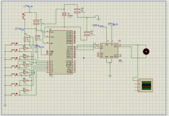
The circuit uses standard power supply comprising of a step down transformer from 230V to 12V and the four diodes forming a bridge rectifier that delivers pulsating dc which is unregulated is regulated to constant 5V dc. The output of the power supply which is 5V is connected to the 40pin of microcontroller and ground is connected to 20pin. Pin no 1 to 7 of port 1 are connected to switches. Pin no 21, 22, 23 of microcontroller are connected to input 1,2, enable pins of motor driver L293D.Pin 3 and 6 are connected to motor terminals.
Four Quadrant Operation of DC Motor:
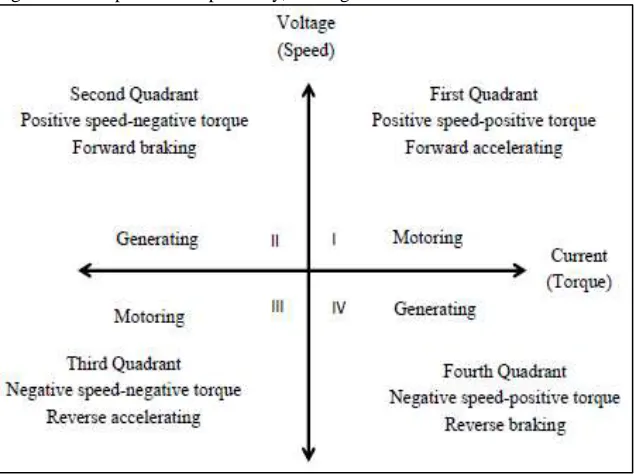
There are four possible modes or quadrants of operation using a DC Motor which is depicted in Figure 2. When DC motor is operating in the first and third quadrant, the supplied voltage is greater than the back emf which is forward motoring and reverse motoring modes respectively, but the direction of current flow differs. When the motor operates in the second and fourth quadrant the value of the back emf generated by the motor should be greater than the supplied voltage which are the forward braking and reverse braking modes of operation respectively, here again the direction of current flow is reversed.
Fig. 2: Four Quadrants Of Operation
Pulse Width Modulation:
Pulse-width modulation (PWM) is a commonly used technique for controlling power to an electrical device, made practical by modern electronic power switches. The average value of voltage (and current) fed to the load is controlled by turning the switch between supply and load on and off at a fast pace. The term duty cycle describes the proportion of on time to the regular interval or period of time; a low duty cycle corresponds to low power, because the power is off for most of the time. Duty cycle is expressed in percent, 100% being fully on.
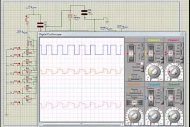
The main advantage of PWM is that power loss in the switching devices is very low. When a switch is off there is practically no current, and when it is on, there is almost no voltage drop across the switch. Power loss, being the product of voltage and current, is thus in both cases close to zero. PWM works also well with digital controls, which, because of their on/off nature, can easily set the needed duty cycle. PWM has also been used in certain communication systems where its duty cycle has been used to convey information over a communications channel. The duty cycle determines the speed of the motor. The desired speed can be obtained by changing the duty cycle. The PWM in microcontroller is used to control the duty cycle of DC motor. The PWM pulses generated from the microcontroller are viewed for various duty cycles in the simulation done in proteous software.
Motor Driver IC:
L293D is a dual H-bridge motor driver integrated circuit (IC). Motor drivers act as current amplifiers since they take a low-current control signal and provide a higher-low-current signal. This higher low-current signal is used to drive the motors.
L293D contains two inbuilt H-bridge driver circuits. In its common mode of operation, two DC motors can be driven simultaneously, both in forward and reverse direction. The motor operations of two motors can be controlled by input logic at pins 2 & 7 and 10 & 15. Input logic 00 or 11 will stop the corresponding motor. Logic 01 and 10 will rotate it in clockwise a nd anticlockwise directions, respectively. Enable pins 1 and 9 (corresponding to the two motors) must be high for motors to start operating. When an enable input is high, the associated driver gets enabled. As a result, the outputs become active and work in phase with their inputs. Similarly, when the enable input is low, that driver is disabled, and their outputs are off and in the high-impedance state.
III.
C
OMPLETE DRIVE SYSTEMTo implement this project work three software have used. These are: 1) Kiel
2) Proteus 3) Flash Magic
Kiel:
Kiel compiler has been used to convert high level language into Hex code.
Proteus:
It has been used to simulate the result in software.
Positron Boot Loader:
It has been used to burn Hex code into microcontroller
The overall block of the system is implemented in the proteous software and the response and the operation of the motor is viewed as in figure 3.
The response of the motor connected can be seen visually according to the program fed into the microcontroller and the operations are carried accordingly. It is the easiest way to check whether the hardware will get the desired output. The changes can be made to get the desired output and the operation can be carried out accordingly.
IV.
H
ARDWARE DESCRIPTIONThe following procedures are carried out for the for the four quadrant DC motor speed control operation using microcontroller. Here seven switches are interfaced to MC to control the speed of motor in four quadrants. When start switch is pressed the motor starts rotating in full speed being driven by a motor driver IC L293D that receives control signal continuously from the microcontroller. When clockwise switch is pressed the motor rotates in forward direction as per the logic provided by the program from the microcontroller to the motor driver IC. While forward brake is pressed a reverse voltage is applied to the motor by the motor driver IC by sensing reverse logic sent by the microcontroller for a short time period due to and reverse brake switch is pressed the microcontroller delivers a logic to the motor driver IC that develops for very small time a reverse voltage across the running motor due to which instantaneous brake situation happens to the motor. PWM switch is used to rotate the motor at varying speed by delivering from the microcontroller a varying duty cycle to the enable pin of the motor driver IC. It starts from 100% duty cycle and reduces in steps of 10% when it is pressed again and finally reaches to 10% duty cycle and the process repeats. Stop button is used to switch OFF the motor by driving the enable pin to ground from the microcontroller command accordingly.
V.
P
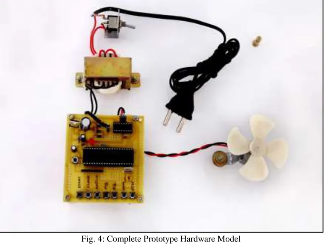
RACTICAL IMPLEMENTATIONThe practical implementation of the four quadrant control of the DC motor is shown in figure 4. The hardware is designed and the operation has been done based upon the program written in the microcontroller for the four quadrant operation of the DC motor and the speed is also controlled by using PWM technique which instantaneous brake situation is applied to the motor.
Fig. 4: Complete Prototype Hardware Model
Fig. 5: Flow Chart Diagram Of System
VI.
E
XPERIMENTAL RESULTSSimulation Results Using Proteus Software:
The simulated waveform of microcontroller based dc motor speed control for the four quadrant modes of operation i.e. clockwise, anticlockwise movement, forward and reverse braking is given below.
Fig. 6: (B). Waveform Of Anti-Clockwise Movement Of Dc Motor
Fig. 6: (C). Waveform Of Forward Braking Of Dc Motor
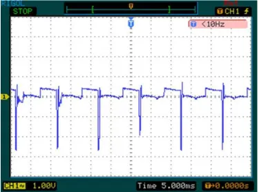
Hardware Implementation:
The hardware model has been designed and implemented for speed control of dc motor using AT89S52 microcontroller and the waveform of input pulse given to dc motor from pin of microcontroller has been observed on digital CRO. And the waveforms for four quadrant modes of operations are achieved for different duty cycle achieved.
Fig. 6: (E). Clockwise Movement Of DC Motor
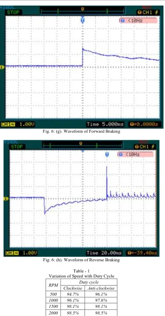
Fig. 6: (g). Waveform of Forward Braking
Fig. 6: (h). Waveform of Reverse Braking
Table - 1
Variation of Speed with Duty Cycle
RPM Duty cycle
Clockwise Anti-clockwise
500 94.7% 96.1%
1000 96.1% 97.6%
1500 98.1% 98.1%
2000 98.5% 98.5%
From the table no.01, it has been observed that as the duty cycle of dc motor increases its speed also increases.
2) In this project the DC Motor is interfaced with AT89S52 Microcontroller using L293D Motor Driver. Push Button switches are provided to control the speed of the dc motor. The average DC value delivered to motor can be varied by varying the duty ratio of the PWM.
3) From the experiment it has been observed that in forward and reverse braking mode the dc motor runs for a short duration and after this it stops.
VII.
C
ONCLUSIONThe prototype hardware model for the four quadrant dc motor speed control using microcontroller is designed. . A simulated model has been developed by proteus software and then result has been verified using a prototype hardware model. In the proposed model, the PWM technique has been used to control the speed of dc motor. By variation in duty cycle, applied voltage varies therefore speed of dc motor can be controlled. The waveform of input pulse given to DC motor has been taken for different values of duty cycle and it has been observed that speed of dc motor is directly proportional to duty cycle, i.e. as the on time duty cycle increases the speed of dc motor also increases. The waveform of input pulse of dc motor has been taken for forward and reverse braking mode and it has been observed that amplitude of waveform became high for very short duration and after that amplitude becomes zero.
In the experimental result it has been observed that some harmonics are occurred. It is due to different nonlinear electronic components such as diodes, transistors etc. present in the prototype developed model. It has been observed that amplitude of waveform obtained in proteus simulated model is 5v while it is 3.5v for waveform obtained from experimental result i.e. amplitude of waveform obtained from experimental result is less. It is due to the fact that some voltage drop has been taken place across resisters used in the prototype developed model.
It is practical and highly feasible in economic point of view and has an advantage of running motors of higher ratings. It gives a reliable, durable, accurate and efficient way of speed control of a DC motor. The program is found to be efficient and the results with the designed hardware are promising. The developed control and power circuit functions properly and satisfies the application requirements. The motor is able to operate in all the four quadrants successfully. Regenerative braking is also achieved.
A
CKNOWLEDGMENTSI would like to thank BIT Sindri for giving me the opportunity to use their resources and work in such a challenging environment.
First and foremost I take this opportunity to express my deepest sense of gratitude to my guide Mrs. Rekha Jha for her able guidance during my project work. This project would not have been possible without her help and the valuable time that he has given me amidst her busy schedule. I would also like to extend my gratitude to my friends and senior students of this department who have always encouraged and supported me in doing my work.
Last but not the least I would like to thank all the staff members of Department of Electrical Engineering who have been very cooperative with us.
R
EFERENCES[1] B.K Bose., Power electronics and motor drives recent technology advances, Proceedings of the IEEE International Symposium on Industrial Electronics, IEEE, 2002, pp 22-25.
[2] Devika R. Yengalwar, Samiksha S. Zade, Dinesh L. Mute “Four Quadrant Speed Control Of Dc Motor Using Chopper” International Journal Of Engineering Sciences & Research Technology,vol. 4 issue 2: February, 2015, ISSN: 2277-9655,pp 401-406.
[3] “DS1103 PPC Controller Board”, Germany: dSPACE, July 2008. Janice Gillispie Mazidi. “Books on Microcontroller: 8051 microcontroller and embedded systems”
[4] Maiocchi.G., “Books on DC motors: Driving DC Motors “BL.Theraja. “DC Motors and drives “
[5] Muhammad Ali Mazidi and Janice Gillispie Mazidi, “The 8051 Microcontroller and Embedded Systems, Pearson Prentice Hall Publication”.
[6] Shruti Shrivastava1, Jageshwar Rawat2, Amit Agrawal “Controlling DC Motor using Microcontroller (PIC16F72) with PWM” International Journal of Engineering Research (ISSN : 2319-6890),Volume No.1, Issue No.2, pp : 45-47 01 Dec. 2012.
[7] S.M.Rangdal1, Prof. G.P.Jain2 “Speed Control Of Dc Motor Using Microcontroller” International Journal of Advanced Technology in Engineering and Science www.ijates.com Volume No.02, Issue No. 12, December 2014 ISSN (online): 2348 – 7550.
[8] Snehlata Sanjay Thakare and Prof. Santosh Kompelli “Design and implementation of dc motor speed control based on pic microcontroller” International Journal of Engineering and Computer Science ISSN: 2319-7242, Volume - 3 Issue -9 September, 2014 Page No. 8075-8079.
[9] Valter Quercioli., “Books on PWM technique: Pulse Width Modulated Power supplies”.