Multilevel Home Security System using Arduino
& GSM
Viswanatha V. Venkata Siva Reddy R.
Assistant Professor Professor
Department of Electronics & Communication Engineering Department of Electronics & Communication Engineering Acharya Institute of Technology, Bangalore, India REVA University, Bangalore, India
Ashwini Kumari P. Assistant Professor
Department of Electrical & Electronics Engineering REVA University, Bangalore, India
Abstract
This paper presents sensor based multilevel security system. It offers three levels of security using PIR sensor, temperature sensor, password based digital lock. It is basically wireless sensor network using Arduino Mega 2560 and GSM .This wireless sensor network is made up of sub systems like PIR sensors, fire alarm module which is made by temperature sensor, digital lock system and burglar alarm module into a single automated architecture for the purpose of practical implementation in smart home system. When sensors get signals or obtained signals crosses reference value, Arduino controller sends an information to the user having mobile through the GSM (Global System for Mobile Communication) module over a wireless communication .All the modules work parallel and independently by sharing computational resource i.e. microcontroller together. Hence a low cost, accessible, auto-configurable, secure and remotely controlled solution has been developed for smart home security system.
Keywords: Arduino MEGA, GSM, LCD, LM35 Sensor, PIR Sensor
_______________________________________________________________________________________________________
I. INTRODUCTION
Security System
Wireless security is the prevention of unauthorized access or damage using wireless networks as a systematic solution for home security. Wireless technologies like Bluetooth. Infrared, Wi-Fi and GSM are available to access the system for security and automation [3], [6]. Now days everybody wants to take care to prevent intrusion because crime is increasing day by day. The proposed system characteristics involve remote control of appliances, system security and intrusion control using GSM based wireless technology.
Block Diagram
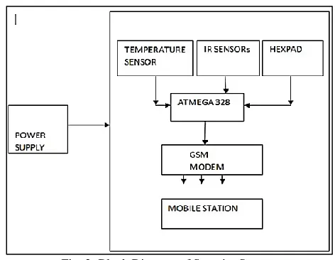
The block diagram of the security system is as shown in fig.2 and it consists mainly of the blocks as follows, Source
Sensing block
Decision making block Alert system
Fig. 2: Block Diagram of Security System
Source
Power to the Arduino microcontroller is supplied through a 12 V, 1 ampere adapter. Sensing Circuit
Temperature sensor: LM35 is employed to monitor ambient temperature conditions in the premises. The LM35 is better compare to linear temperature sensor which is standardized in Kelvin, since a large constant voltage is subtracted from the output to get convenient centigrade scaling which is done by device itself [4],[6]. No user is required to do this. The LM35 is easily interfaced to readout or control circuitry because of its special characteristics of low-output impedance, linear output and precise inherent calibration.
Keypad
In matrix keypads, four columns and four rows combination is use to determine the state of the button to the microcontroller or any other host device. Pushbutton is used in each key, one end is connected to one row and the other end is connected to one column [4]. Based on the state of columns, microcontroller can understand which button is pressed.
Decision Making Block
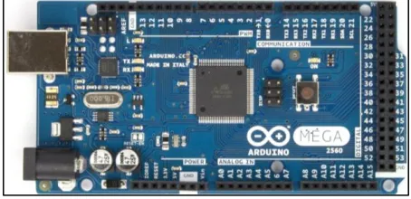
Here, Arduino mega microcontroller board is used which decides the appropriate action to be taken as and when required. The Arduino Mega can be powered via the USB connection or with an external power supply.
The power source is selected automatically. External (non-USB) power can come either from an AC-to-DC adapter or battery [5]. Leads from a battery can be inserted in the Gnd and Vin pin headers of the POWER connector.
Alert System
In the hardware Implementation, alert system consists of buzzer which produces audio signal and this device can be mechanical, piezoelectric or electromechanical system [3]. Typically it is used in alarm, timers and confirmation of user inputs such as mouse click or keystroke
GSM Module
II. WORKING PRINCIPLE
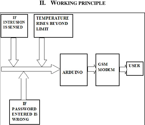
Fig. 3: Block Diagram Depicting the Working of Security System
Three level home security systems are depicted in terms of blocks as shown in fig.3 and is explained as follows. 1) Connect a 12V, 1A adapter to GSM module after inserting the SIM card and then wait for the network initialization. 2) Connect USB cable to Mega 2560 with laptop or connect one more adapter to Mega 2560 DC pin to supply the power. 3) As soon as we press the password set push button, the LCD will start to display.
4) When display shows “SET 5 digit password”, enter 5 digit password which will be shown on the LCD display. Set the password and lock it.
5) Enter the correct password then press “A” to unlock. Only if the password is correct, motor will rotate and door will open. 6) Two PIR sensors are used for two separate rooms and one PIR sensor is located in each room.
7) If any intrusion is sensed in any room then the buzzer attached to the PIR sensor starts alarm and simultaneously the camera motor will also rotate to track the motion so that the viewer can see the live recording.
8) PIR sensors can be tested by creating an obstruction in front of any PIR sensor, the buzzer will beep and camera motor will rotate.
9) Then, check with wrong password. If password is incorrect, then the motor controlling door will not rotate and simultaneously the message is sent to the owner and also when someone try to change the password, the message will be sent to the owner. 10) After the user enters the premises by entering the correct pass key and needs to reactivate the system while leaving, “B” key is
to be pressed.
11) If the owner wants to change the password then enter the present correct password and press “C” key. Enter the new password to set the new password.
12) The temperature sensor, LM3 senses the temperature when it exceeds the set ambient temperature of the premises. A message “temperature is not normal in the room”, is sent by the GSM module alerting the owner of the same.
Table – 1
The Entire Methodology is summarized in Table 1
If, Password is incorrect Temperature rises beyond limit
Intrusion is detected Then,
These outputs will be fed into the Arduino
Arduino with the help of GSM module and a SIM card will send a
message accordingly
The owner of the registered number will receive the
message
III. SOFTWARE & PROGRAM
Software
Program
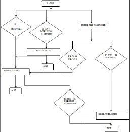
Logic of the program used for the implementation of hardware using Arduino controller is depicted in terms of flowchart shown in fig.4
Fig. 4: Flowchart of Three Levels of Home Security System
IV. HARDWARE IMPLEMENTATION
1) Arduino Mega 2560 2) Temperature sensors 3) H bridge motor driver circuit 4) Passive Infrared Sensor
5) Global system for mobile communication 6) Keypad
7) Liquid Crystal Display
Hardware
Complete hardware implementation is depicted in the fig.5
V. RESULTS
Case 1. When PIR Sensor Detects Intrusion, the Message given in fig.6 Sent to the Owner
Fig. 6: Message Received by the Owner
Case .2 when Temperature Exceeds Ambient Limits, the Message given in fig.7 Sent to the Owner
Fig. 7: Message Received by the Owner
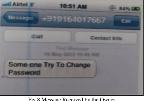
Case. 3 When Change in Password is detected, the Message given in fig.8 sent to the Owner
Fig.8 Message Received by the Owner
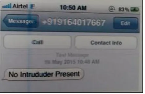
Fig. 9: Message Received by the Owner
VI. CONCLUSION
Home Security is a main concern worldwide. Since the technology is getting advanced, various home based security systems are developed and implemented to protect our homes from illegal invasion. In this paper, multilevel home security (MHSS) which has been designed and developed consists of motion sensor, temperature sensor, GSM module, LCD display and an alarm circuit. Alarm system is to alert the house owner and neighbors and also sends alert messages to the house owner.
Hence to conclude the basic three levels of home security system, the use of Arduino Mega microcontroller lets us control many subsystems and at the same time letting the use of single system. The system can be further developed using automatic gas breaking detector/motion detector so the solution can be integrated with these and other security systems. In addition this system will be self-contained power supply system and not prone to electric failure.
REFERENCES
[1] Deepali Javale,Assistant Professor,Dept. of Computer Engg ,MAEER's MITCOE Pune, India ;Mohd. Mohsin Student ,Dept. of Computer Engg,MAEER's MITCOE ,Pune, India ;Shreerang Nandanwar ,Student ,Dept. of Computer Engg ;MAEER's MITCOE ,Pune, India ;Mayur Shingate Student ,Dept. of Computer Engg ;MAEER's MITCOE ,Pune, India. (2013, March). Home Automation and Security System Using Android ADK. International Journal of Electronics Communication and Computer Technology (IJECCT). [Online]. 3(2). Available:
[2] http://www.academia.edu/14501543/Home_Automation_and_Security_System_Using_Android_ADK.
[3] Dinesh Suresh Bhadane Department of E&TC Sandip Polytechnic, Nashik, Maharashtra, India ;Monali D. Wani, Department of E&TC Sandip Polytechnic, Nashik,Maharashtra,India ;Sanjeev. A. Shukla, Department of E&TC SITRC, Nashik, Maharashtra, India.( 2015, February). A Review on Home Control Automation Using GSM and Bluetooth. International Journal of Advanced Research in Computer Science and Software Engineering.[Online].5(2).Availablr: https://www.scribd.com/document/267053611/A-Review-on-Home-Control-Automation-Using-GSM-and-Bluetooth.
[4] Bhargav B. Patel, Assistant Professor, E & C Department, GTU University, Gujarat, India ;Keyur Chauhan, Assistant Professor, E & C Department, GTU University, Gujarat, India ;Suchita B. Patel , Assistant Professor, M.Sc IT Department, S.P University, Gujarat, India.(2015,January). Wireless Visual Visitor Verifier for Home Security Using Smart Phone. International Journal of Advanced Research in Computer Science and Software Engineering.[Online].5(1).Available: http://ijarcsse.com/Before_August_2017/docs/papers/Volume_5/1_January2015/V5I1-0246.pdf.
[5] Ms. Gunjan Jewani,Department of Computer science & Engineering,Nagpur,India ;Prof. Shubhangi Borkar,Department of Computer science & Engineering,Nagpur Institute of Technology,Nagpur ,India.(2015,February). Review On-A Knock Based Security System. - International Journal on Recent and Innovation Trends in Computing and Communication.[Online].3(2).Available: http://www.ijritcc.org/download/ICAET15TR011797.pdf.
[6] Wikipedia. Home automation, http://en.wikipedia.org/wiki/Home_automation. [7] BTBee Alliance, “Products and Certification Overview,” BTBee Alliance. [8] The Android open source project, http://source.android.com/.