User Interface of Test System Test Management and Programming Tool
Sets
Test Executable (TE)
System Under Test (SUT) Implementation
Adaptor
Platform Adaptor
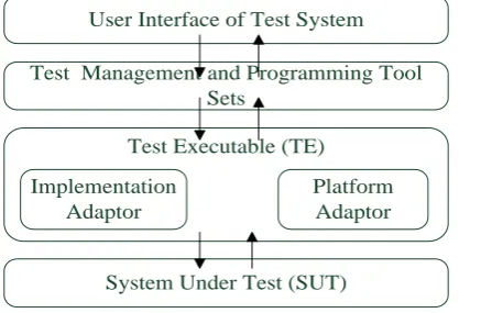
Figure 1. Abstract test system model
A Micro-Kernel Test Engine for Automatic Test
System
Shuai Wang
1. Department of Automation, Tsinghua University
2. Tsinghua National Laboratory for Information Science and Technology, Tsinghua University, Beijing, China Email: [email protected]
Yindong Ji
1. Department of Automation, Tsinghua University
2. Tsinghua National Laboratory for Information Science and Technology, Tsinghua University, Beijing, China Email: [email protected]
Shiyuan Yang
Department of Automation, Tsinghua University, Beijing, China Email: [email protected]
Abstract—In traditional automatic test solutions, a test engine usually encompasses all functions in its kernel, including compiling test program, generating test event chain, scheduling test process and executing test events. This makes the engine tightly coupled with test language and the system under test, so that it is difficult to maintain, optimize and extend the test engine. In order to solve these problems, a micro-kernel test engine is designed and implemented based on the service oriented architecture. This micro-kernel approach decouples function modules to make the test engine kernel independent of the system under test and the test language. This also makes the test engine more modularized, so that the debugging process and maintenance work of the engine can be much easier. With new compiling component and test adapters, the engine kernel can be extended for new test methods or reused in new test applications. The application example and extensibility analysis discussed in section 6 show the feasibility of this micro-kernel test engine.
Index Terms—automatic test system, test engine, micro-kernel, service oriented architecture
I. INTRODUCTION
Automatic testing is an efficient approach to cope with the test application of systems which are more and more complex. A typical automatic test system usually consists of multiple function components: user interface of test system, test management and programming tool sets, and test executable unit.
A general test system model is shown in Fig. 1 and the functions of components are described as follows.
User interface of test system help testers use test system.
Test management and programming tool sets are used to manage test requirement, test case, test program, fault trace and so on.
Test executable unit is responsible for the runtime behavior of test program. In other words, actual test execution takes place at this component.
The heart of an automatic test system is the executable unit that glues everything together and makes the desired test possible. It is also called test execution environment or test engine. In the following discussion, we use test engine to denote it.
A test engine can be seen as a virtual machine that provides the run-time execution environment for the test programs. Compiling a test program, creating test event chain (test process has the same meaning) according to the program, scheduling the test process and managing the running of each event are the essential chores of a test engine. These functions should be coded and embedded in every automatic test system solution. In this sense, every automatic test system should entail a test engine in one way or another.
These monolithic kernels are tightly coupled with the systems under test and the specific test languages [1]-[5]. When the system under test (SUT) changed (function update or sub-system replaced with products of different manufactures), the updating work of the test engine is cumbersome. At the same time, the debugging, updating and maintenance for the test engine are also problems, when it is monolithic. At the worst situation, we may need to redevelop a new test engine.
However, we often want to have the freedom to change the system under test without developing entirely new test engine from the scratch for each function, and at the same time ease the work of debugging and maintenance of the engine. Especially, we hope that the invariant part can be reused or embedded in forthcoming test applications. To this end, we are interested in isolating the core invariant portion of test engine, and providing a generalized framework for building other functions on top of the core to reuse the invariant portion in different application as well as optimization of existing engine components without the need for engine-wide changes.
In this paper, a micro-kernel test engine is designed and implemented for this aim.
The desired micro-kernel [6] approach for building automatic test engine (ATE) is based on analogy with operating systems [7]. In operating systems that are based on micro-kernel architecture, a very basic set of services are provided by the operating system core (e.g., process identifiers and address spaces). Using such primitive services, the rest of the system services are in fact built outside the core (e.g., file systems and networking). A micro-kernel operating system provides an easy and safe way of adding new system/kernel services, such as new network protocols and file systems.
We borrow this design idea into our test engine. Similarly, a micro-kernel ATE provides an easy way to add new objects under test (equipment or system) or engine functions without the need for an overhaul of the entire engine implementation.
In this paper, we argue the micro-kernel principle, decoupling each function module and remaining only the test process scheduling capability in the kernel. Following this, a micro-kernel test engine is designed based on service oriented architecture. All other functions supporting test execution are implemented as services for the kernel. The benefits of this micro-kernel method are summarized as follows.
1) The engine is modularized, so the debugging process and maintenance work of the engine are much easier.
2) The updating work of the engine becomes easier. 3) The reuse of the invariant portion of test engine in
other application domain becomes possible. The rest of this paper is organized as follows. Section 2 reviews some other test engines. The guiding principles are discussed in section 3. The design of this micro-kernel test engine is introduced in Section 4. The implementation details of the micro-kernel are described in Section 5. One application of this engine and its
extensibility are discussed in section 6. Finally, conclusion is presented in Section 7.
II. BACKGROUND AND RELATED WORK
In some of our current railway domain projects, we are pursuing a special automatic test system. This test system is used to assure the function features of train control system [8] which is a distributed system. The train control system is composed of numbers of sub-systems which may be manufactured by different companies and run on different platforms. The primary goal of our test system is to make testing for this system more efficient to support the heterogeneous applications. Because the changeability and complexity of train control system, the test engine needs to be extended and reused easily. At the same time the debugging and maintenance work should be alleviated. To this aim, the micro-kernel test engine is designed.
A. Related work
Traditional test environments are usually dependent on the implementations of system under test and the adopted test languages. Several test execution environments are illustrated as follows.
TTCN-executable: The Testing and Test Control Notation (TTCN) [9] is a test specification and implementation language. It was first developed for conformance and interoperability testing of communication protocols in telecommunication domain and now have been extended and broadened to allow the testing of local/distributed and reactive/proactive systems. The test execution environment for TTCN is used to parse the TTCN program and execute the test. Many research institutions and companies have done a lot of work to develop the test engines for TTCN to make the program of TTCN executable, e.g. the test system for maglev control system design [10] and TTCN-3 test harness [11-12].
The separation between the engine and test adapter is suggested in TTCN reference model, so TTCN executable unit is decoupled with SUT. But all implementations depend on the TTCN language notations, so the extension of the test engine capability is constraint within the ability of TTCN standard. The reuse of the engine may be also constrained in the TTCN application domain. Due to the coupling of other functions, the maintenance and updating may also be a cumbersome work.
difficult, and the maintenance of the test execution environment may be another problem.
AGEDIS [14]: The aim of this project is to increase the efficiency and competitiveness of the software industry by automating software testing, and improving the quality of software while reducing the expense of the testing phase. AGEDIS achieves this by developing a methodology and a set of tools for the automation of software testing with emphasis on distributed component-based software systems. The primary goal of the test execution environment [15] for it is to support test execution on the heterogeneous distributed system. The implementation of this environment has no SUT platform or language dependencies, but its architecture does not have a structural separation between the functions of test program compiling and test events executing. The maintenance and updating of the test environment may be a difficult work.
Till now, most test engines focus on one test application of specific system, and they are usually monolithic kernel engines, in which the monolithic kernel aims at a full-fledged, all-encompassing set of test engine functions. All function components are coupled tightly is the main problem for the extension, maintenance and reuse of the test engines.
III. GUIDING PRINCIPLES
Different form traditional test system solutions that all functions are implemented in the core of test engine, a micro-kernel test engine focuses exclusively on providing test process scheduling capabilities, leaving all of the remaining functions out of the kernel. The purpose of developing a micro-kernel test engine is to make the maintenances and extension of the engine easy as well as reuse the invariant portion in forthcoming applications. Thus a micro-kernel test engine kernel must be designed in a way that is independent of (1) specific test language, (2) particular ways of interacting with resources (3) platform and implementation of system under test.
A. Test programming language compiling
Test programming language is used to define test case and test execution process. Several test languages have been developed for different test applications [16]-[17]. In order to make the test executable, test engines which depend on the notations of a specific test language are implemented. In different test system, different compiling components of test engine are implemented to generate test event chain from test program. In the micro-kernel approach, the engine core needs be independent of the test language to support test engine extension and reuse. So a universal description model for test event chain is used to define the compiling outcome of different test languages. The details will be discussed in following section. The model must:
Be able to describe test process. We can use the elements of model to define a test process for different test purpose and methods.
Be extensible: The model must supply extension mechanism to add new model elements.
B. Resource Invocation
Many test engines assume some specific ways of interacting with resources and do not consider that, in a complex test environment, they may be required to interact with a variety of resources, from human to different systems, applications, or even machines and equipments. Each resource may require a specific kind of interaction, from reply/request to iterated attempts of task acceptance and fulfillment. A micro-kernel test engine cannot make any assumptions on the way that resources are invoked, or on the way that each resource carries out its work. In fact, a micro-kernel engine core should not invoke any resource directly; rather, it should provide a mechanism that allows it to interact with any resource in a uniform manner. This way it is possible to invoke any number or type of resources without having to make any changes of the test engine.
A kind of adapter, resource adapter is designed out with this requirement. In essence, they are application wrappers that allow the test engine to invoke resources according to a uniform engine-defined interface. However, a specific resource adapter assumes that a certain kind of resource will be invoked. In the test system for circuit, for example, several adapters are used to retrieve information from different kinds of measure equipments. The interaction process with different resources is implemented by different adapters. New test adapter will be designed to adapt the change of resources and the addition of new resources, but the test engine core needs no changes.
C. Interaction with systems under test
Most test engine implementations depend on the implementation of system under test, so test engine is tightly coupled with the implementation of SUT. Specific test interaction way is assumed between test engine and SUT. But when the system under test is distributed, the problems appear.
Distributed system may run in different host environments (physically separated in a network). Different programming languages may be used to code the different sub-systems in the system under test. Test system is required to interact with a variety of sub-systems under test. Each sub-system requires a different kind of interaction ways, from communication protocols to reply/request manners. A micro-kernel test engine core cannot make any assumptions on the way that interacts with SUT but need to provide a uniform interface to invoke SUT so that we can add new sub-system under test, update engine and reuse the core in other application domain without having to make any changes to the implementation of test engine core.
Compiling
Test Program
Test Adapter
Resource Adapter
Time handler
Interrupter
System under test
Test process
scheduling
Resource
Test Process
Store
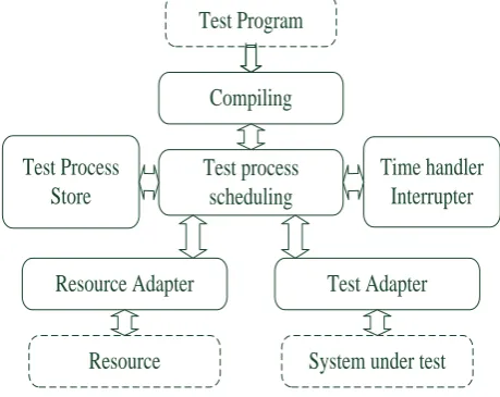
Figure 2. Architecture of the test engine
engine in the high level, so the details of interaction is concealed behind this interface.
IV. MICRO-KERNEL TEST ENGINE DESIGN
In this section, we introduce the design details of the micro-kernel test engine. The design rule is uncoupling all engine functions. The kernel of engine only focuses on the test process scheduling capability, and other functions are all extracted out of the engine kernel.
In our design, this micro-kernel test engine is implemented based on service-oriented architecture (SOA) [18]. Each function is taken as a service for the execution of test program. Combining the required functions we can implement the automatic test system. New functions can be implemented under this architecture, and combined with existing functions to fulfillment new test application requirement; and the debugging process is restricted in the scope of each function module, so the update and maintenance of the engine is easy to achieve. At same time, some of the function modules can be reused in other test application domains.
A. Architecture of the test engine
On the whole, the micro-kernel test engine has two layer meanings:
1) The function of test engine kernel is very simple. It only deals with the scheduling approach of test process. In other word, when one test event has finished, the test engine kernel continues the test process according to the test event chain.
2) The functions are modular and are coupled loosely. So the updating, extension and reuse are easy to achieve.
The architecture of test engine designed based on SOA is shown in Fig. 2. Implementing reusable and removable services as system components is the key motivation in using SOA for developing system solutions. In our design of micro-kernel test engine, all functions are implemented as services in order to modularize and reuse each module. Because of the modularized design, the maintenance and update of each module are easy.
The functions of main modules are stated as follows:
Compiling: This module is used to compiles the test program and the implementation of this module is according to the test language definition. The test event chain which describes test process has been generated.
Test process scheduling: This module is the kernel of test engine, and it is responsible for executing test events and scheduling test process. The engine kernel is independent with the platform and language of SUT.
Test Adapter: Different test adapters must be implemented and they are used to handle the messages communication with SUT and SUT process call. Test engine kernel doesn’t send the test data to SUT directly but test adapters instead. The test data defined in test program is only the application related data, but not packed with communication protocol and mechanism. The test adapter composes the abstract test data into the type which the SUT can recognize, and then send the data to SUT through specific physical link. When the implementation of system under test changed, new test adapters are developed for the concrete test execution, and other functions have no need to change.
Resource Adapter: Resource adapter is responsible for interaction with specific resource. With the resource adapters, test system need not to take care of the invoking details. A uniform invoking manner is used for different resources. New resources can be invoked by test system through developing new resource adapters.
Test process store: This function module is used to store test process instance when the test program is very long so that the whole test event chain cannot be stored in the memory.
Of course, other function modules can be implemented to help engine finish specific test purposes, such as time handler and interrupter.
B. Core services
The kernel of the test engine focuses on the scheduling capability of the test event. It needs assuring that the test process executes according to the process definition from one test event to another. The kernel needs to solve two problems: scheduling test process and maintaining test process context.
The test process model is the foundation of test process scheduling. The test process model described in [19] is adopted by this paper.
Test process model: A test program usually describes a test logic which is composed of test events and the executing logic of these events. Compiling outcomes of different test languages are modeled as a universal test process model to make the engine kernel independent of specific test language. The test process model (TPM) is defined as:
TPM:: ( , , , , ) E Q L V t . (1) (1) E:: ( e e1
, ,
2,
em), E is a set of test events.0
m , m is the number of the events;
Start node Test input data D1 D2 D3 D4
D5 D6
D1
D2 Test event1
D7
D7
D3 Test event3
D8
D8
D6 Test event6
D11 D7
D4
Test event2
D9
D9 D5 Test event5
D10
End node Test output data
D7 D8 D9 D10 11
SUTs Resources SUTs
Resources
e1
e2
e3
Xf
l
1l
2l
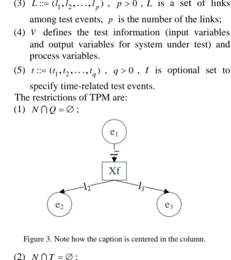
3Figure 3. Note how the caption is centered in the column. (3) L:: ( l l1
, ,
2,
lp), p0, L is a set of linksamong test events, p is the number of the links; (4) V defines the test information (input variables
and output variables for system under test) and process variables.
(5) t:: ( t t1
, ,
2,
tq) , q0 ,t
is optional set to specify time-related test events.The restrictions of TPM are: (1) N Q ;
(2) N T ;
(3) Q
b f, , b is the starting tag and f is the ending tag.A test process model can be represented by a directed graph G( , )N E , where the set N{ ,n1 nn} of nodes
represents the set of specified events of the test process and the directed edges E represent the execution order of events. In general, the graph of a certain test process contains a start node, an end node, several test event nodes and links which are associated with the execution logic of these events.
In the implementation of test engine, node is a base class. Node with specific properties and type can execute specific test event. The type of the node defines its runtime behavior. A test process model is shown in Fig. 3. In this example, e1, e2, e3 are test interaction events
(inputting test data or receiving test outcome). Xf is a
“XOR-fork” test control event. The runtime behavior of Xf is discussed in [19].
Test process scheduling: It focuses on how to schedule the test process execution. We adopt tokens to schedule test process and the test event which has a token can execute its behavior. The tokens are transferred from one event to next to prompt the test process. In TPM, test events trigger tokens transfer between events through links. Events are therefore responsible for the continuation of the test process execution. Links are associated with execution direction.
When a token arrives on a node, a certain event must be invoked, regardless of what that event will effectively do. The event may dispatch a task to SUT or resource, or it may request a remote machine operation, or it may perform some operation on a variable, for example. The input data for any SUT, as well as the output data that were brought back to the engine kernel by means of events, are represented as message. A signal is generated with specific link after certain test event has finished. Continuous execution of the test process is done by the leave method of event objects. When receiving an unnamed signal, the token will leave its current event over the default leaving link. When a link-name is specified in the signal, the token will leave its event over the specified link.
Take the test process model described in Fig. 3 for example. The instance of this model is constructed and illustrated in Fig. 4. The start event and the end event are attached in the test event chain in order to define the beginning and ending of this test process. In some complex test application scenario, the end nodes may be more than one.
A token is created for the main path of test execution after the test process instance has been constructed. This token is called the root token of the test process and it is positioned in the start event of the test process. A start signal instructs the token to start the process execution. Then, each test event triggers the token transferring between events through the links. When the token arrived in the end event, the process end event will be executed to stop the process execution.
Test process context: The test process context is about process variables and process resources. Process variables are key-value pairs that maintain the state of test process.
V. MICRO-KERNEL TEST ENGINE IMPLEMENTATION
In this section, we will introduce the implementation of the micro-kernel test engine.
A. Compiling component
Test program Compiling
e2
e3
e4 e5
Test language Compiler Test even chain
Figure 5. Example of test process scheduling B. Kernel of the test engine
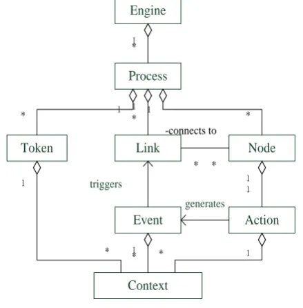
The test engine kernel essentially comprises a set of objects that are inter-related according to the principles described in the last section. At the top of the class hierarchy, class engine provides the access to the set of currently active processes, as depicted in Fig. 6.
The engine object behaves as a singleton object and it is the single point of entry for every other component accessing the test engine kernel. The engine object contains a list of references to process objects. A process is comprised of a set of node and link objects that refer each other. A node references its input and output link objects, while a link references its input and output node objects. A token is pointer to node and which node has a token can run its behavior. A node will usually contain an action which encapsulates a certain event code, an invocation of some resource, an interaction with SUT or an inner action.
Context is used to maintenance the context of test process. Action objects, event objects and token objects make use context to execute test process instance. Many different type events which have specific runtime behaviors are defined by inheriting the node class.
Usually, nodes are responsible for propagating the process execution. Their methods for this function are the most complex part of the engine kernel. Each token represents a path of execution. A node can create and destroy tokens, and also launch tokens transfer over links. Basically, each node has the following options for propagating the process execution:
1) Propagating the execution over one of the leaving links of the node. This means that the token that originally arrived in the node is passed over one of the leaving links. The node can execute some custom action and then continue process execution automatically without waiting.
2) Creating new paths of execution. A node can create new tokens. Each new token represents a new sub-path of execution and each new token can be launched over the node's leaving links.
3) Ending paths of execution. A node can end a path of execution. That means that the token of this path is ended and the path of execution is finished.
C. Test adapter
Test adapters are used to help engine kernel to finish interacting with SUTs. To the aim discussed in last section, the adapter design pattern [20] is used to supply a uniform interface for engine kernel to execute test event. Based on this, numbers of test adapters are developed for concrete test execution. This makes it possible to invoke any number or type new SUTs without having to make any changes to other function of test engine. The class diagram of test adapter is shown in Fig. 7.
From Fig. 7, we see that appropriate test adapter facilitates the interaction between the SUT and the test engine kernel. The physical and electrical characteristics, the identification and classification, the intended platform are all supported by test adapters.
generates Engine
Process
Node Link
Token
Action
* -connects to
*
Context Event
1 *
1
* 1* 1 *
1
* 1 * 1
*
1 1
triggers
Figure 6. Simplified class diagram for the engine Kernel
Engine/SUT
+request() <<interface>>
Target
+Specificrequest() Adaptee
Engine/SUT
+request() testAdapter
Resource adapters have similar implementation principle with test adapters, so we will not introduce it here.
VI. EXAMPLE STUDY AND EXTENSIBILITY ANALYSIS
In this section, we have designed one example to study the feasibility of this test engine. Our implementation currently runs on a distributed simulation system which is used to simulate China train control system level three.
A. Example
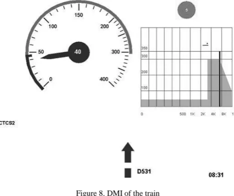
This is an example that the test engine is used to test train control system for the function features validation. We design a small test program (written with test language defined by another research of ours) to test whether the train control system can successfully receive speed limit command and then execute the expected actions according to the system requirement specification. From test system view, this test program is composed of three test events, sending temporary speed restriction message to train control system, observing executing result from train control system, comparing test result and expected result. The test engine kernel is responsible for scheduling this test event chain. At the same time, to implement testing, two specific test adapters are developed for this application. One is responsible for interacting with train control center and the other is responsible for interacting with auto train protect equipment. The test results are shown in Fig. 8.
When the train is near or in this speed limit span, from the DMI of train we can see that the speed of the train is lower than the limit speed which is shown in Fig. 8. We can conclude that the test engine has good applicability for such a professional area.
B. Extensibility analysis
According to the discussion in the above sections, this test engine can be easily extended and reused. We will explain this in the following four aspects.
Event type extension: Each event objects has a specific type. The event type determines what will happen when a token arrives in it at runtime. A pre-implemented set of
engine. In the future, we can write custom code to extend runtime behavior of node by action object. The extended event type is used to implement special test applications.
Changes of system under test: When a new sub-system under test is inserted into the test environment or the implementation of certain sub-system is changed, the test environment need to support these changes. By the micro-kernel approach, a new test adapter is developed for these changes, and other components of test engine do not need to be updated.
Service extension: The service oriented architecture make the kernel easy to integrate new service to fulfill new test requirements. For example, the time handler can be developed to supply time service for engine kernel to support the test engine to cope with time-related test applications.
Reuse in new application domains: The engine kernel can be reused in new application domains by developing new compiling component to support new test language, new test adapters and resource adapters.
VII. CONCLUSION
In traditional automatic test system solutions, all the functions of test engine are implemented in the kernel of engine so that the engine is tightly coupled with test language and system under test. Especially, this makes the updating, maintenance and reuse of the test engine difficult. To solve these problems, a micro-kernel test engine based on SOA is designed to separate the core invariant portion from variant portion of test engine.
Instead of developing all the functions in the core of engine, the micro-kernel test engine introduced in this paper only provides test process scheduling capabilities in its kernel, leaving all of the remaining functions out of the kernel. Based on the idea of SOA, all the functions of test engine are designed as services. Specific compiling component compiles the test program to a test process model which can be executed by engine kernel. This decouples the coupling between the engine kernel and test language. Test adapters are responsible for interacting with SUT. The physical/electrical characteristics, the identification/ classification, and the intended platform are all supported by test adapters. Resource adapters are responsible for the resources invocation. These two kind adapters make the engine independent of specific SUT or resource.
Based on the micro-kernel approach, the test engine is independent of (1) specific test languages; (2) particular ways of interacting with resources; (3) implementation of system under test.
The architecture of this micro-kernel test engine gives an easy way to extend or reuse the engine. Extension of event type supports new test method or purpose. Extension of test adapter supports new systems under test or changes of system under test. Extension of resource adapter supports new resources. Extension of new service component supports special test application.
ACKNOWLEDGMENT
This work was supported in part by the National Key Technology R&D Program under Grant 2009BAG12A08, the R&D Foundation of the Ministry of Railways under Grant 2009X003 and the Research Foundation of Beijing National Railway Research and Design Institute of Signal and Communication.
REFERENCES
[1] P. Lerchbaumer, A. Ochoa and E. Uhlemann, “Test environment design for wireless vehicle communications,” Vehicular technology conference, pp.2214-2218. 2007. [2] Wenli Dong, “Multi-agent test environment for
BPEL-based web service composition,” Cybernetics and Intelligent Systems, 2008 IEEE Conference, pp.855-860, 2008.
[3] J. L. Amsell, “Enhanced integrated satellite factory test environment,” AUTOTESTCON 2003, IEEE Systems Readiness Technology Conference, pp.597-603, 2003. [4] A. A. Khwaja, “An MFC based multi-threaded test
environment for the validation of an embedded automotive microcontroller,” Technology of Object-Oriented Languages and Systems 2000, pp.15 – 24, 2000.
[5] S. J. Youn, Y. J. Byun and et al., “Design and implementation of software simulation platform for ATM switching systems,” Proceedings of the 1997 International Conference on Parallel and Distributed Systems, pp.184-187, 1997.
[6] P. B. Hansen, “The nucleus of a multiprogramming system,” Communication of the ACM, Vol.13, Issue 4, pp.238-241, 1970.
[7] J. Liedtke, “On micro-kernel construction. ACM SIGOPS Operating Systems Review,” Vol.29, Issue 5, pp.237-250, 1995.
[8] A. Zimmermann, G. Hommel, “Towards modeling and evaluation of ETCS real-time communication and operation,” Journal of Systems and Software, Vol.77 Issue 1, pp.47-54, 2005.
[9] ETSI, “Methods for testing and specification (MTS): The testing and test control notation version 3, Part 1: TTCN-3 core language,” European technological standards Inst.,” ETSI standard ES 201 873-1, 2007.
[10]J. C. Wang, “Research of TTCN-3 based vehicle on-board equipment test system of maglev control system,” thesis. [11]J. C. Okika, A. P. Ravn and et al., “Developing a TTCN3
test harness for legacy software,” Proceedings of the 2006 international workshop on Automation of software test, pp.104-110, 2006.
[12]X. Z. Xing, L. Zhang, F. Jiang, S. Y. Cheng and X. Jiang, “Combined symbolic and concrete execution of TTCN-3 for automated testing,” Proceedings of the 2008 International Symposium on Information Science and Engineering, pp.58-61, 2008.
[13]S. Pakin, “The design and implementation of a domain-specific language for network performance testing,” IEEE Transactions on Parallel and Distributed Systems, Vol.18 Issue 10, pp.1436-1449, 2007.
[14]A. H., K. Nagin, “The AGEDIS tools for model based testing,” ACM SIGSOFT Software Engineering Notes. Vol.29 Issue 4, pp.129-132, 2004.
[15]A. Hartman, A. Kirshin and K. Nagin, “A test execution environment running abstract tests for distributed software, Proceedings of SEA 2002.
[16]T. R. Mitchell, “A standard test language – GOAL,” Proceedings of the 10th workshop on Design automation, pp.87-96, 1973.
[17]R. Kapur, M. Lousberg and T. Taylor, “CTL the language for describing core-based test,” International Test Conference, pp.131-139, 2001.
[18]N. Wilde, and S. Simmons, “Understanding features in SOA: some experiences from distributed systems,” Proceedings of the 2nd international workshop on Systems development in SOA environments, pp.59-62, 2008. [19]S. Wang, Y. D. Ji, S. Y Yang, “A Novel Test Process
Modeling Method for Automatic Test,” Proceedings of the 2nd IEEE International Conference on Computer Science and Information Technology, pp.459-463, 2009.
[20]E. Gamma, R. Helm, R. Johnson, and J. Vlissides, “Design patterns-elements of reusable object-oriented software,” Addison-Wesley Publishing, Reading, Mass, 1995.
Shuai Wang was born in Changchun, Jilin Province, China, on April 3, 1981. He received his B.S. degree in control science and engineering from Beijing Institute of Technology University, Beijing, China in 2004. Currently, he is a PH.D candidate working in fields of control science and engineering at Tsinghua University. His major research interests include system test, fault diagnosis and reliability analysis.
Yindong Ji was born in Beijing, China in 1962. He received his B.S. and M.S. all from the Department of Automation, at Tsinghua University, in 1985 and 1989, respectively. His main research areas are digital signal process, fault diagnosis, modeling & simulations. He is a member of IEEE.
Prof. JI is with the Department of Automation, and Tsinghua National Laboratory for Information Science and Technology, Tsinghua University, Beijing, China. He has published over 60 papers in journals. His current research interest is in the area of train control system of high speed railway.
Shiyuan Yang was born in Shanghai, China, in 1945. He received his B.S. and M.S degree from Tsinghua University in 1970 and 1981, respectively.