A New Test Data Compression Scheme
Ling Zhang1,2 Jishun Kuang1 1
School of computer science Huangshi Institute of Technology Huangshi, China 2
School of Computer and Communication, Hunan University Changsha , China
Abstract—With the improvement of technology, more cores
are placed on a single chip to form a system. The volumes of test data becomes a challenges for circuits test. The paper presents a test data compression which uses hybrid prefix code and a new test set regenerating algorithm. In essence, the technique uses two formats of prefix to encode for the new regenerated test set, and the regenerated test set is better suitable to our compression scheme. So it gain better compression ratio. Experimental results show that the proposed compression solution could re duce test data volume effectively with a simple decoding architecture.
Index Terms—hybrid prefix code, embedded core testing,
test data compression, test regeneration
I. INTRODUCTION
The increase in integration density has resulted in a tremendous increase in the test data volume needed to test those chips. The large test data volume not only increase the testing time but may also exceed the tester memory capacity. To reduce the testing time and cost, it is necessary to reduce the test data volume.
Test volume reduction can be achieved by utilizing built-in self test(BIST) and test compression techniques. BIST solution reduces the need for an expensive ATE as on-chip pattern generators and signature compaction are used. In practice, BIST may not always replace other test methods for the long time needed to detect random pattern resistant faults[1].
There are extensive works on the test compression which used to speed up the ATE-SoC interaction during test. These works are used to compress the precompued test-data set(TD) which often provided by core vendor, to a smaller test set TE(|TE|<|TD|) which is then stored in the ATE’s memory, and an on-chip decoder decompresses TE to TD to be applied to the system under test.
Some test compression techniques are based on utilizing structural information of the circuits. Decompression-based schemes[2] and broadcast-scan-based schemes[3,4]. Other test compression techniques do not require structural information, they compress TD to a smaller volume TE. example of this techniques include alternating run-length coding[5], Golomb coding[6], FDR coding[7], EFDR coding[8] and run-length Huffman coding[9] ,VC9R[1], select Huffman coding[10] . In addition, there are also some techniques based on LFSR encoding[11] and dictionary based compression[12]. A particularly attractive feature of algorithmic strategy for test compression is that it does not require any redesign of IP core.
This paper presents a new compression solution which based on new generated test set and new suitable code
compression scheme. The new compression scheme achieves a higher compression ratio with carefully use ATPG process to generate new better suitable test set based on a given test set, and only requires a very small decoder. In addition, the proposed technique does not perform any circuits’ structure modification.
The rest of this paper is organized as follows. Section II discusses hybrid prefix code scheme and the corresponding decoding architecture. A new algorithm for test regeneration based on a given test set without harm the fault coverage is given in Section III. Experimental results are shown in Section IV. Section V is devoted to a simple conclusion for the proposed test compression solution.
II. TEST REGENERATION FOR COMPRESSION The section presents how to regenerate new test set which is better suitable to the proposed encode scheme.
Compared with previous encode schemes which only use one format prefix, the hybrid encode scheme has longer codeword for run-length of one. Much run lengths of one would harm the compression ratio. For achieving higher compression ratio, an algorithm for regenerating test set based on a given test set which has very few run-lengths of one and more run length of longer run-run-lengths without harm the fault coverage is given.
The objective of the proposed algorithm is to make as few as possible run-lengths of one and as more as longer run-length in the test set based on a given test set while minimizing the increase in the number of test vectors, and maintaining the original fault coverage.
We use the solution of TVD[13] to increase the number of unspecified bits per vector first. TVD is a process of decomposing a test vector into its atomic components. An atomic component is a child test vector that is generated by relaxing its parent test vector for a single fault f, that is, the child test vector contains the assignments necessary for the detection of f. Besides, the child test vector may detect the other faults in addition to f. for example, consider the test vector tp-010110 that detects the set of faults Fp={f1,f2,f3}. Using the relaxation algorithm[14], tp can be decomposed into three atomic components, which are t1=(f1,01xxxx), t2=(f2,0x01xx) and t3=(f3,x1xx0). Every atomic component detects the fault associated with it and may accidentally detect other faults. An atomic component cannot be decomposed any further because it contains the assignments necessary for detecting its fault.
decomposed into subvector(s) in the following manner. The atomic component for each fault detected by the decomposed vector is obtained. These atomic components are then incrementally merged to create new subvectors which have as few as possible run lengths of one and as more as longer run-lengths. Sub-vectors are created in this way until all the faults detected by the parent vector are covered; thus, the longer run-lengths may appear in this process. At last, we merged the new sub-vectors with acceptable vectors to minimize the number of the vectors without raising the number of run-lengths of one. We don’t allow any changing on the essential fault which only has one vector could detect it in the process of decomposed process.
A simple example is presented to illustrate the algorithm. The given test set has three test vectors, and we first make step 1 and 2 of the algorithm and the corresponding results are given in the table I.
The decomposed vector 3 is decomposed into the atomic components for each fault detected by vector 3. In table II, f1 and f2 are not essential faults and f3 is essential faults, so the corresponding atomic component xxxxx00x is not removed or changed in our algorithm. The new test set is given in the table III after performing the algorithm
TABLE I. GIVEN TEST SET AFTER ALGORITHM OF STEM1 AND 2
vectors Faults detected
acceptable Has essential faults
xxx00111 {f1,f4} yes No
xx100x00 {f2,f5} yes No
0x101001 {f1,f2,f3} no Yes
TABLE II. DECOMPOSE FOR VECTOR3
Atomic components of vector3
Faults detected
is essential fault
0x1xx00x {f1} no
0xx01x0x {f2} no
xxxxx001 {f3} yes
TABLE III. LAST TEST SET USING ALGORITHM
Last new test set Faults detected
xxx00111 {f1,f4} xx100x00 {f2,f5} xxxxx001 {f3}
III. NEW COMPRESSION SCHEME
This section presents the new compression technique and the corresponding decoding architecture.
A. New compression scheme
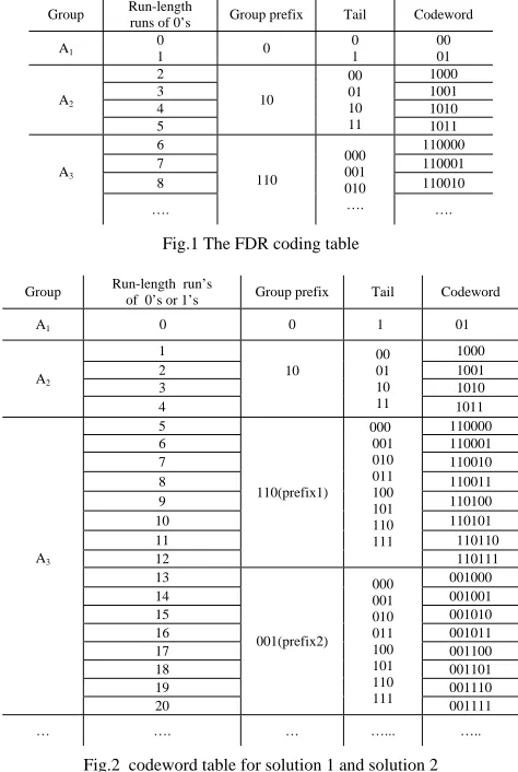
We first review FDR coding and its application to test data compression[7]. The FDR code is a data compression code that maps length runs of 0’s to variable-length codewords. The encoding procedure is illustrated in Fig.1. The reader is referred to [7] for a detailed
run length of zero and one. We use two formats of prefix in the new compression scheme, which we called hybrid prefix code.
The new hybrid prefix code was given in Fig.2. It uses two formats prefix from the group of three and consists two parts—group prefix and tail. The prefix identifies the group in which the run-length lies and the tail identifies the member within the group. For achieving target compression ratio, the new generated test set based on a given test set would have very few run lengths of one and more longer run-lengths. The detailed presentation on the new test set generation algorithm will be given in the next section.
Group Run-length runs of 0’s Group prefix Tail Codeword
A1
0
1 0
0 1 00 01 A2 2 10 00 01 10 11 1000 3 1001 4 1010 5 1011 A3 6 110 000 001 010 …. 110000 7 110001 8 110010 …. ….
Fig.1 The FDR coding table
Group Run-length run’s
of 0’s or 1’s Group prefix Tail Codeword
A1 0 0 1 01
A2 1 10 00 01 10 11 1000 2 1001 3 1010 4 1011 A3 5 110(prefix1) 000 001 010 011 100 101 110 111 110000 6 110001 7 110010 8 110011 9 110100 10 110101 11 110110 12 110111 13 001(prefix2) 000 001 010 011 100 101 110 111 001000 14 001001 15 001010 16 001011 17 001100 18 001101 19 001110 20 001111 … …. … …... …..
Fig.2 codeword table for solution 1 and solution 2
The FDR code is very efficient for compressing data that has few 1’s and long runs of 0’s for it only maps variable-length runs of 0’s to variable-length codewords. However, data streams are composed of both runs of 0’s and runs of 1’s, so only encoding for run-length runs of 0’s is not always efficient[5]. The new hybrid prefix encode scheme could encode for both run-length runs of 0’s and run-length runs of 1’s.
encoding both of them as EFDR which presented in [8] using codewords described in Fig. 3 which uses two formats prefix encoding for run-length runs of 0’s and run-length runs of 1’s, respectively, which we called
solution3.
Group Run-length Prefix1 Tail Codeword for 1 Prefix2 Codeword for 0
A1 -- --- --- --- --- ---
A2
1
10 00 01 10 11
1000
01
0100
2 1001 0101
3 1010 0110
4 1011 0111
A3
5
110 000 001 010 ….
110000
001
001000
6 110001 001001
7 …
110010 …
001010 …
… …. … …... …..
Fig.3 codeword table for solution 1 and solution 2
B. Decompression architecture
The decoder architecture given here could be used for
solution1 and solution 2 which presented in last section. The decoder architecture for hybrid prefix scheme of
solution 3 is very simple, the decoder for alt-FDR[5] could be used to it after a very small modification, and we don’t give the detailed presentation for it.
out FSM
Log2k bit counter
(K+1)bit counter
T
sel shift dec1 rs1
Counter_in rs2 dec inc sel
en
bit_in
v b_out
Clk
bit2
Con
Mapping logic
out1 bit3
sel
out2
⊕
Counter_in1
Fig.4 the decoder architecture for hybrid prefix coding
The decoder architecture for hybrid solution 1 and
solution 2 is shown in Fig.4. It only needs deleting or retaining the architecture in the broken line when used on
solution2 and solution1, respectively. The FSM based architecture makes a small modification on the FDR decoder[5]. An additional simple mapping logic is added to map the prefix in the codewords to its corresponding binary representation length.
As shown in Fig.2, the run length in the grouth k(k>2) is from( 2k+1-11) to (3*2k-12) for the prefix1 and from (3*2k -11) to (2k+2-12) for prefix2; thus, the binary representations of the run-length identified by prefix1 and prefix2 are computed as in Fig.5, respectively. The binary
representations of the run-length identified by the tail are same as the corresponding tail in the codewords.
Group Prefix1 Corresponding binary representation Prefix2
Corresponding binary representation
A3 110 101(5)
001 1101(13)
A4 1110 10101(21) 0001 100101(37)
A5 11110 110101(53) 00001 1010101(85)
A6 111110 1110101(117) 000001 10110101(181)
A7 1111110 11110101(235) 0000001 101110101(363)
… … … … …
Fig.5 corresponding binary representations of prefixes
As shown in Fig.4, the bit_in is the input of the FSM, and the en is an enable signal for the decoder. The signal of counter_in is used to shift the prefix to the (k+1)-bit counter through the mapping logic, and the signal of counter_in1 is used to shift the tail into the k-bit counter. The signal of shift is used to control the mapped prefix and tail of the codeword to shift in k-bit counter, the signal of dec1 controls the counter’s decrement, and rs1 signal is used as the counter’s reset signal. The signal of sel is used to choose different hybrid prefixes. Log2k bit counter is used to count the length of the prefix and tail so as to identify the group, and the signals of inc and dec are used to control the counter’s increment and decrement, respectively. The mapping logic is used to map the prefix to its corresponding binary representation run length.
The detailed operation of the decoder is described as follows:
• The en, shift and inc signals are high, the signal bit_in, sel and counter_in control the prefix shift in the k-bit counter, log2k bit counter make increment. Because our solution has two prefix formats, so we have two situations.
① If bit_in begins as 1, then sel is high, until the bit_in is 0 which identifies the end input of the prefix, then shift and inc is low, and the signal sel, bit2 and bit3 control the mapping logic to map the prefix to the corresponding run length then shift in the k-bit counter.
② If the bit_in begins as 0, then in the next cycle, if the bit_in is 1, then dec and sel control the counter make decrement, and dec1 and sel1 control the k-bit counter make decrement; if the k-bit_in is 0, sel is low, until the bit_in is 1 which identifies the end input of the prefix, then the shift is low, and the signal sel, bit2 and bit3 the mapping logic to map counter_in to its corresponding value and then shift in the k-bit counter.
TABLE IV. COMPRESSION RATIO FOR MINTEST TEST SETS
circuit TD solution 1 solution 2 solution3
S5378 23754 53.52 58.52 52.81
S9234 39273 46.56 50.56 47.64
S13207 165200 81.47 83.95 81.96
S15850 76986 66.26 70.76 68.41
S38417 164736 62.08 66.59 51.25
S38584 199104 63.30 66.39 62.17
average --- 64.16 66.13 60.70
TABLE V. COMPARISON OF COMPRESSION RATIO WITH OTHER COMPRESSION SOLUTIONS
circuit FDR[7]
Alt-FDR[5] EFDR
[8]
VC9[1]
RL Huffman
[9]
SL Huffman
[10]
Block
Code [17] solution 2
S5378 48.02 50.77 53.67 51.64 53.75 55.10 54.98 58.52 S9234 43.59 44.96 48.66 50.91 47.59 54.20 51.19 50.56
S13207 81.30 80.23 82.49 82.31 82.51 77.00 84.89 83.95
S15850 66.22 65.83 68.66 66.38 67.34 66.00 69.49 70.76
S38417 43.26 60.55 62.02 60.63 64.17 59.00 59.39 66.59
S38584 60.91 61.13 64.28 65.53 62.40 64.10 66.86 66.39
average 57.21 60.57 63.30 62.90 62.96 62.57 64.47 66.13
• The tail part is shifted in until the log2k bit counter resets to 0, the dec2 signal is then goes high, the counter is decremented. And the signal rs2 indicates when it is in the zero state.
• Like the decoding of the prefix, the FSM ouput 0’s corresponding to the tail followed by a zero.
IV. EXPERIMENTAL RESULTS
The experiments were conducted on a series of ISCAS 89 circuits on a Pentium with a 3.0GHz processor and 512 MB of memory. The algorithm is programmed using C++ language under linux environment based on the ATPG tools of atom[15] to regenerate the new test set on the given test set of mintest[16].The experimental results are given in Table IV and TableV.
The compression ratios of the proposed solution are shown in Table IV. the compression rate (CR) is defined as follows: CR=(TD-TE)/TD The third, fourth and fifth column in the table are the compression ratio for solution1,
solution2 and solution 3, respectively. As is evident in the Table, the proposed hybrid prefix code scheme which uses two formats prefix and regenerates test set based on a given test set achieves higher reduction rate.
We compare the compression ratio of our scheme with other several classical compression techniques in table V, from the second to the ninth column are the compression ratio results for the FDR[7], alt_FDR[5], EFDR[8], VC9[1], run length Huffman coding[9], select Huffman coding[10] and block merging[16]. As is evident from the table, the proposed hybrid prefix code provides an improved compression rate without harm fault coverage if the ATPG process is executed carefully.
V. CONCLUSION
This paper presents a new compression solution which
use ATPG process to generate new better suitable test set based on a given test set, and only requires a very small decoder. In addition, the proposed technique does not perform any circuits’ structure modification and uses a small decoder and achieves a higher compression ratio. The experimental results show that the proposed technique achieves higher compression ratio with very low overhead.
REFERENCES
[1] M. Tehranipoor, M. Nourani, K. Chakrabarty.
“Nine-Coded Compression Technique for Testing Embedded Cores in SoCs”, IEEE transactions on very large scale integration(VLSI) systems. Vol.13,2005,pp 719-731.
[2] Janusz Rajski, Jerzy Tyszer, Mark Kassab and Nilanjan
Mukherjee. “Embedded Deterministic test”, IEEE transactions on computer-aided design of integrated circuits and systems, Vol.23, No.5 2004, pp,776-792.
[3] F. Hsu,K.Butler, and J. Patel, “A case study on the
implementation of the Illinois scan architecture,” in proc. Int. Test Conf. (ITC’01),2001, pp.538-547.
[4] Laung-Terng Wang, Zhigang Wang, Xiaoqing wen,etc.
“VirtualScan: Test Compression Technology Using Combinatioal Logic and One-Pass ATPG”, IEEE Design & Test of Computers.2008.pp.122-129
[5] A. Chandra, A. Chandrabarty, “a Unified Approach to
Reduce SOC Test Data Volum, Scan Power and Testing Time”,IEEE Transactions on Computer-aided design of integrated circuits and system. Vol.22.No.3, 2003, PP: 352-362
[6] A.Chandra, K.Chakrabarty, “System-on-a-chip Test-data
Compression and Decompression Integrated Circuits and Systems” IEEE transaction on computer-Aided design of integrated circuits and systems. Vol.20, 2001, pp.355-368.
[7] A.Chandra, K.Chakrabarty. “Frequency-diredted
Code”. IET Computers & Digital Techniques. 2008, pp. 155-163.
[9] NOURANI M, Tehranipour. M, “RL-Huffman encoding
for test compression and power reduction in scan applicaiton”, ACM trans.Des. AUTOM. Electron. Syst. 2005, 10, (1), pp. 91-115
[10]JAS A., GOSH-DASTIDAR J., NG M., TOUBA N.: ‘An
effcient test vector compression scheme using selective Huffman coding’, IEEE Trans. Comput. Aided Des., 2003, 22, (6), pp. 797–806
[11]A. Jutman, Igor. Alekejev, J. Raik, etc, “Reseeding using
Compaction of Pre-Generated LFSR Sub-Sequences”, IEEE. 2008. pp: 1290-1295
[12]M. Knieser, F. Wolff, C.Papachristou, D.Wyer, and D.
McIntyre, “A technique for high ratio LZW compression,” in Proc. Design Automation Test in Europe, 2003, pp. 116-121.
[13]EL-MALEH A., OSAIS Y.E.: ‘Test vector
decomposition-based static compaction algorithms for combinational circuits’,ACM Trans. Des. Autom. Electron. Syst., 2003, 8, (4),pp. 430 – 459
[14]EL-MALEH A., AL-SUWAIYAN A.: ‘An effcient test
relaxationtechnique for combinational and full-scan sequentialcircuits’. VTS ‘02: Proc. 20th IEEE VLSI Test Symp.,Washington, DC, USA, 2002, p. 53
[15]Ilker Hamzaoglu and Janak H. Patel, “New Techniques for
Deterministic Test Pattern Generation,” Proceedings of the VLSI Test Symposium,1998, pp. 446-452
[16]I.Hamzaoglu and J.H.Patel, “Test set compaction
algorithms for combinational circuits,” in Proc. Int,Conf. Computer-Aided Design,1998, pp,283-289
[17]A.H.EL-Maleh, “efficient test compression technique