CFD-based Study of Velocity Distribution among
Multiple Parallel Microchannels
PAN Minqiang1* Zeng Dehuai1,2 Tang Yong1 and Chen Dongqing1 1
School of Mechanical and Automotive Engineering, South China University of Technology, Guangzhou510640, China
2
School of Mechatronics and Control Engineering, Shenzhen University, Shenzhen518060, China
1*
Email: [email protected]
Abstract—A three-dimensional computational fluid dynamics (CFD) model was used to calculate the velocity distribution among multiple parallel microchannels with triangle manifolds. The influences of structural parameters on velocity distribution among microchannels were analyzed. The simulation results showed that the velocity distribution became more uniform with larger microchannel length, depth or smaller width. Larger horizontal ordinate, longitudinal ordinate and radius of inlet/outlet, smaller lengths of bottom and side of symmetrical manifolds could favor obtaining narrow velocity distribution among microchannels. Symmetrical manifold structure could achieve more uniform velocity distribution among microchannels than that asymmetrical manifold structure.
Index Terms—computational fluid dynamics, velocity distribution, parallel microchannel, manifold
I. INTRODUCTION
Considerable progress of micro-fabrication techniques over the last decade has enabled microchannel reactors to be widely applied in multiple fields[1-4]. The two fundamentally different constructions of microreactors are monolithic construction and laminated-sheet structure[5]. The latter is considered as one of the preferred microreactor constructions, in which multiple sheets patterned with a large number of equal parallel microchannels are stacked and then bonded together to form a unit, as shown in Fig.1. The microchannels fabricated in the sheets generally have the characteristic dimensions on the order of hundreds of microns, resulting to a much larger surface area-to-volume ratio than that of conventional macroscopic reactors.
Equal fluid velocities in the microchannels are beneficial for improving the heat and mass transfer efficiency as well as achieving high selectivities and conversions. Although manifolds are usually incorporated to enhance the flow uniformity[8-10], it is difficult to obtain equal velocity distribution among multiple parallel microchannels. The structural parameters of manifolds and microchannels play an important role on the velocity distribution, however, current geometrical design largely depends on the rule of thumb. It is important, therefore, to
design reactor geometries to achieve relatively narrow velocity distribution among microchannels.
laminated unit
microchannel cross-section microchannel sheet laminated microreactor
Figure1.Structure of laminated microchannel reactors[6-7]
Some researches were focused on the modeling and simulation of flow or velocity distribution among multiple parallel manifolds. Commenge et al.[11] developed an approximate pressure drop model to examine the features of fluid flow through microchannel reactors. Amador et al.[12] applied an electrical resistance network model to study the differences of flow distribution among microchannels with two manifold structures. Tonomura et al.[13] proposed a CFD-based optimization method for the design of plate-fin microchannel devices with rectangular manifolds.
In our previous works, we studied the characteristics of velocity distribution among non-uniform cross-section microchannels[14], parallel microchannels with complex manifold geometries[15] and asymmetrical manifolds[16] by a physical model. On the basis of these research findings, the objective of the present work is to further summarize the characteristics of velocity distribution among multiple parallel microchannels with triangle manifolds by using a three-dimensional computational
fluid dynamics(CFD) model. The influences of structural
parameters on velocity distribution among microchannels are analyzed by an evaluating parameter for the uniformity degree of velocity distribution.
II. MODEL DESCRIPTION
As shown in Fig.1, the microchannel sheet usually consists of an inlet, an outlet, multiple parallel
Manuscript received January 5, 2009; revised February 13, 2009; accepted February 28, 2008.
microchannels and two triangle manifolds, one is inlet manifold, the other is outlet manifold. In addition, the direction of fluid is perpendicular to the inlet and outlet. In order to investigate the characteristics of flow patterns inside the microchannel plate, the flow zone of fluid is extracted from the plate as a research object, as shown in Fig.2. To study the effects of aspect-ratio of microchannel on the velocity distribution, the microchannel with rectangular cross-section is selected here.
Rectangular microchannels in the cross-section Inlet manifold
Outlet manifold Inlet
Outlet Flow direction
Figure2. The model built for the analysis of velocity distribution among microchannels with triangle manifolds
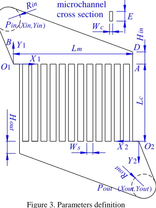
The inlet manifold and outlet manifold is generally centrosymmetric, however, it is not clear that whether the symmetrical geometry favors in obtaining uniform velocity distribution. In the following section, the effects of symmetry of two manifolds on the velocity distribution are investigated. Therefore, the structural parameters of microchannels and manifolds are firstly defined to facilitate understand of the shape change. As presented in Fig.3, the microchannel length, width, depth, interval and
number are defined as Lc, Wc, E, Ws and N, respectively.
The channels are numbered up from 1st to N th along the
direction of O1A.
X1
Y1 H
in
Rin
O1
Wc
L
c
Lm
Ws
R ou t
H
ou
t
Pin (Xin,Yin)
Pout (Xout,Yout)
Y2
O2
X2
E microchannel cross section
A
B D
Figure 3. Parameters definition
During the design of manifolds, take the inlet manifold
for example, the lengths of bottomLm and side Hin are
firstly determined, and then the position and magnitude of
the inlet Pin are chosen, two tangent lines to the Pin
through O1 and D are respectively made, which yields the
final manifold shape. Therefore, the position of inlet or outlet governs the manifold shape. Two coordinate systems are established to determine the relative position of manifold and inlet or outlet, respectively.
As for the inlet manifold, O1 is chosen as the origin of
the coordinate system. The bottommost line O1A of
manifold is selected as the axis X1 and right as positive,
while the vertical plumb O1B perpendicular to O1Aas
axis Y1 and up as positive. O2 is selected as the origin of
the coordinate system for the outlet manifold, and the
establishment of axis X2 and Y2 is similar to that of the
axis X1 and Y1. But the direction of X2 and Y2 are left and
down as positive, respectively. The coordinate of inlet Pin
and outlet Pout in respective system are defined as (Xin,Yin)
and (Xout,Yout). The radius of inlet and outlet are defined
as Rin and Rout, respectively.
In this work, a specific case of 20-microchannel model with centrosymmetric manifolds was illustrated in Table 1. The microchannel distribution was assumed to be
uniform, therefore Ws was determined by Lm when Wc
was determined in advance. This model was seemed as the basic one, and then one or two of structural parameters was independently adjusted while fixing other variables for studying the effects of each structural parameter on the velocity distribution. In addition, the comparison of velocity distribution among microchannels with symmetrical and asymmetrical manifolds was studied. The investigated structural parameters were listed in rightmost volume of Table 1. The microchannel
number N was maintained invariant to reduce calculation
times.
Table 1 The basic and investigated structural parameters of microchannel model
Variables Basic
model
Investigated parameters
Microchannel structural parameters
N 20 -
Lc(mm) 20 10;20;30;40;50
Wc(µm) 500 100;200;300;400;500
E (µm) 500 100;200;300;400;500
Manifold structural parameters
Xin /Xout (mm) -2 -4;-2;-1;0;2
Yin /Yout (mm) 7 5;6;7;8;;10
Rin/Rout (mm) 2 0.5;1;2;2.5;3
Hin/Hout (mm) 2 1;2;3;4;5
Lm (mm) 20 14;16;20;22;30
III. CFD SET-UP AND ANALYSIS
The model was meshed by hexahedral cells, as depicted in Fig.4. The flow pattern was assumed to be laminar in the microchannels. The governing equations were Navier-Stokes equation with non-slip boundary condition and energy equation. In addition, negligible gravity was used to evaluate the flow characteristics.
Figure 4. The model meshed by hexahedral cells
The liquid water(density as 998.2 kg·m-3 and kinetic
viscosity as 1.003×10⁻³ kg·m-1·s-1) under 300K were
selected as the fluid. The boundary conditions used were the velocity value in the Z direction of the inlet and the freedom outlet flow. The entrance velocity of fluid was preset to 1mm/s. The outlet pressure condition was set to zero and the solid boundaries were stationary.
An estimating parameter σU% as defined below is used
to analyze the degree of velocity distribution among
microchannels. The magnitude of σU% indicates the
distributing degree of velocity among microchannels.
Smaller σU% suggests more uniform velocity distribution.
%
1
(
)
1
100
1
2
×
⎟⎟
⎠
⎞
⎜⎜
⎝
⎛
−
=
∑
=
N
i m
c U
U
i
U
N
σ
(1)Where Uc(i) is the velocity value of each
microchannel, Um is the mean value of microchannel
velocities, as defined below.
∑
==
Ni c
m
U
i
N
U
1
)
(
1
(i=1, 2, … , N) (2)
IV. RESULTS AND DISCUSSION
A. Effects of Microchannel Structural Parameters
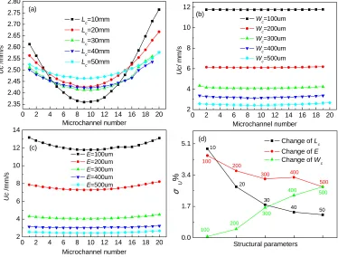
Fig.5 showed how the microchannel structural parameters affected the velocity distribution among microchannels. According to Fig.5(a), the velocity
distributions were asymmetrical with smaller Lc, and the
values of velocities in the microchannels far away from the inlet were larger than that in the microchannels near the inlet. The velocity distribution would be symmetrical when the singular losses in the channels were ignored[11]. The singular losses due to expansion/contraction or change of velocity direction could be possible reasons leading to the deviation of velocity distribution. However, the velocity distribution seemed to be much more symmetrical and uniform with
increasing Lc. That was because pressure drop became
much larger in longer channels[13].
0 2 4 6 8 10 12 14 16 18 20 2.35
2.40 2.45 2.50 2.55 2.60 2.65 2.70 2.75 2.80
Uc
/m
m
/s
Microchannel number
L
c=10mm
Lc=20mm
L
c=30mm
Lc=40mm
L
c=50mm
(a)
0 2 4 6 8 10 12 14 16 18 20 2
4 6 8 10 12
Uc
/ mm/
s
Microchannel number
Wc=100um
Wc=200um
Wc=300um
Wc=400um
Wc=500um
(b)
0 2 4 6 8 10 12 14 16 18 20 2
4 6 8 10 12 14
Uc
/mm
/s
Microchannel number
E=100um
E=200um
E=300um
E=400um
E=500um
(c)
0.0 1.7 3.4 5.1
Structural parameters
500 400
300
200 100
σU
%
Change of Lc
Change of E
Change of W
c
(d)
10
20
30
40 50
100 200
300 400
500
On the other hand, the change of Wc or E showed much
effects on the velocity values than that of Lc, as shown in
Fig.5(b) and (c). The velocity values varied between
2.35mm/s and 2.8mm/s when Lc changed from 10mm to
50mm, while it increased from the 2mm/s to 14mm/s
when Wc or E decreased from 500µm to 100µm. The
velocity value was inversed to the channel width or depth
when the flow Q was constant, which was defined as
below. Since the effect due to the change of flow in each microchannel was much smaller than that of the change
of Wc or E, relatively large change of the velocity values
was produced.
E
W
Q
U
c
c
=
(3)From Fig.5(b) and (c), it could found that the velocity distribution among microchannels appeared symmetrical. The centrosymmetry of the microchannel model could be the cause of symmetrical velocity distribution[11]. However, it was hard to determine the uniformity degree of velocity distribution due to the large change of velocity
values. It could only be estimated by the change of σU%,
as shown in Fig.5(d). Obviously, the velocity distribution became more uniform with larger microchannel depth or smaller width. Therefore, microchannel with high aspect-ratio rectangular cross-section could favor in obtaining narrow velocity distribution among microchannels.
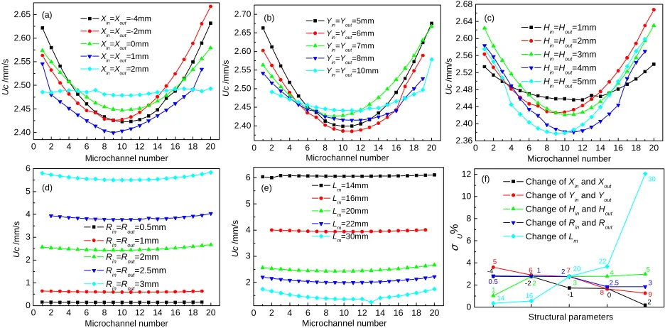
B. Effects of Manifold Structural Parameters
Fig.6 presented the influences of symmetrical manifold structural parameters on the velocity distribution. According to the established coordinate system presented in Fig.3, symmetrical manifold here implied that the structural parameters of inlet manifold and outlet
manifold were equal to each other. In response to the simulation results, it found that the velocity distribution appeared somewhat symmetrical regardless of which parameter. The maximum value appeared the furthest channel from the inlet while the minimum value always in one of the middle microchannels, such as No.9, 10 and 11.
The velocity values changed from 2.3 to 2.7mm/s with
the change of Xin(Xout), Yin(Yout) or Hin(Hout) whereas they
varied much when Rin(Rout) or Lm changed. Since the
entrance velocity was preset to 1mm/s and maintained invariant, the flow in the inlet changed with the change of
Rin, leading to large variation of velocity value in each
microchannel. As for the change of Lm, the most probable
reasons responsible for the change of velocity values lay in two aspects, one was the corresponding change of
microchannel interval Ws in order to assure the uniformity
of microchannel distribution. The other was the change of manifold shape. These reasons also resulted to great change of uniform degree of velocity distribution by the
change of Lm, as shown in Fig.6(f). The value of σU%
increased from 0.35 to 12 when Lm changed from 14 to
30. Fig.6(f) also presented the values of σU% by other
different manifold structural parameters. The values of
σU% varied a little with the change of other parameters.
In addition, it was found that the velocity distribution
became more uniform with larger Xin(Xout), Yin(Yout),
Rin(Rout) or smaller Hin/Hout, Lm. For special, the manifold
changed to approximate right triangle when Xin=Xout=2.
Fig.6(f) indicated that the velocity distribution among microchannels with right triangle manifolds was more uniform than that of the corresponding one with oblique
angled manifolds, here referred to Xin=Xout=-4, -2,-1 and 0.
0 2 4 6 8 10 12 14 16 18 20
2.40 2.45 2.50 2.55 2.60 2.65
Uc
/m
m/
s
Microchannel number Xin=Xout=-4mm
Xin=Xout=-2mm
Xin=Xout=0mm
Xin=Xout=1mm
Xin=Xout=2mm
(a)
0 2 4 6 8 10 12 14 16 18 20
2.40 2.45 2.50 2.55 2.60 2.65 2.70
Uc
/m
m
/s
Microchannel number
Yin=Yout=5mm
Yin=Yout=6mm
Yin=Yout=7mm
Yin=Yout=8mm
Yin=Yout=10mm (b)
0 2 4 6 8 10 12 14 16 18 20
2.36 2.40 2.44 2.48 2.52 2.56 2.60 2.64 2.68
Uc
/mm/s
Microchannel number
H
in=Hout=1mm
Hin=Hout=2mm
Hin=Hout=3mm
Hin=Hout=4mm
H
in=Hout=5mm
(c)
0 2 4 6 8 10 12 14 16 18 20
0 1 2 3 4 5 6
Rin=Rout=2mm
Rin=Rout=2.5mm
R
in=Rout=3mm
Uc
/mm/
s
Microchannel number
R
in=Rout=0.5mm
Rin=Rout=1mm
(d)
0 2 4 6 8 10 12 14 16 18 20
2 3 4 5 6
Uc
/mm
/s
Microchannel number Lm=14mm
Lm=16mm
Lm=20mm
Lm=22mm
Lm=30mm
(e)
0 2 4 6 8 10 12
9 8
7
σU
%
Structural parameters
Change of X
in and Xout
Change of Yin and Yout
Change of Hin and Hout
Change of Rin and Rout
Change of Lm
(f)
5 6
1
2 3
4 5
14 16
20 22
30
0.5
1 2
2.5 3
-4 -2
-1 0 2
Figure 6. Influence of symmetrical manifold structural parameters on the velocity distribution
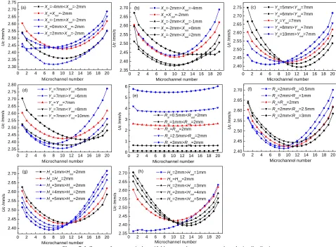
Fig.7 presented the velocity distribution among microchannels with different structures of asymmetrical manifolds. As for all the parameters, only the change of
Rin made great variation of velocity values in the
0 2 4 6 8 10 12 14 16 18 20 2.30 2.35 2.40 2.45 2.50 2.55 2.60 2.65 2.70 2.75 Uc /m m /s Microchannel number X
in=-4mm<Xout=-2mm
Xin=Xout=-2mm
Xin=-1mm>Xout=-2mm
Xin=0mm>Xout=-2mm
Xin=2mm>Xout=-2mm
(a)
0 2 4 6 8 10 12 14 16 18 20
2.35 2.40 2.45 2.50 2.55 2.60 2.65 2.70 Uc /m m /s Microchannel number
Xin=-2mm>Xout=-4mm
Xin=Xout=-2mm
Xin=-2mm<Xout=-1mm
Xin=-2mm<Xout=0mm
Xin=-2mm<Xout=2mm
(b)
0 2 4 6 8 10 12 14 16 18 20
2.40 2.45 2.50 2.55 2.60 2.65 2.70 2.75 Uc /m m /s Microchannel number
Yin=5mm<Yout=7mm
Yin=6mm<Yout=7mm
Yin=Yout=7mm
Y
in=8mm>Yout=7mm
Yin=10mm>Yout=7mm
(c)
0 2 4 6 8 10 12 14 16 18 20
2.35 2.40 2.45 2.50 2.55 2.60 2.65 2.70 2.75 2.80 Uc /mm /s Microchannel number
Yin=7mm>Yout=5mm
Yin=7mm>Yout=6mm
Yin=Yout=7mm
Y
in=7mm<Yout=8mm
Yin=7mm>Yout=10mm
(d)
0 2 4 6 8 10 12 14 16 18 20
0 1 2 3 4 5 6
Rin=Rout=2mm
Rin=2.5mm>Rout=2mm
R
in=3mm>Rout=2mm
Uc
/m
m
/s
Microchannel number
Rin=0.5mm<Rout=2mm
Rin=1mm<Rout=2mm
(e)
0 2 4 6 8 10 12 14 16 18 20
2.40 2.45 2.50 2.55 2.60 2.65 2.70 Uc /m m/ s Microchannel number
Rin=2mm>Rout=0.5mm
R
in=2mm>Rout=1mm
R
in=Rout=2mm
Rin=2mm<Rout=2.5mm
Rin=2mm<Rout=3mm
(f)
0 2 4 6 8 10 12 14 16 18 20
2.40 2.45 2.50 2.55 2.60 2.65 2.70 Uc /m m/ s Microchannel number H
in=1mm<Hout=2mm
Hin=Hout=2mm
Hin=3mm>Hout=2mm
H
in=4mm>Hout=2mm
H
in=5mm>Hout=2mm
(g)
0 2 4 6 8 10 12 14 16 18 20
2.35 2.40 2.45 2.50 2.55 2.60 2.65 2.70 Uc /m m /s Microchannel number
Hin=2mm>Hout=1mm
H
in=Hout=2mm
Hin=2mm<Hout=3mm
Hin=2mm<Hout=4mm
Hin=2mm<Hout=5mm
(h)
Figure 7. Influence of asymmetrical manifold structural parameters on the velocity distribution
According to the simulation results, an interesting conclusion could be summarized as follows: When the structural parameter of inlet manifold was larger than the corresponding one of outlet manifold(such as when
Xin>Xout, Yin>Yout, Rin>Rout or Hin>Hout), the velocity
values in the microchannels far away from the inlet would be larger than that symmetrical one near the inlet. Moreover, the minimum value appeared in the middle channels near the inlet. However, smaller structural parameter of inlet manifold resulted in opposite laws of
velocity distributions. When Xin<Xout, Yin<Yout, Rin<Rout or
Hin< Hout, the velocity values in the channels near the inlet were much larger that the symmetrical one far away from the inlet. The results were accord with the previous ones calculated by a physical model[13].
On the other hand, the velocity distribution among microchannels with symmetrical manifolds appeared much more symmetrical than that with asymmetrical manifolds. Table 2 presented the comparison of the
values of σU% between the symmetrical and
asymmetrical manifolds. The bold numbers in the table represented the same model, that is, the symmetrical manifold structure. It found that the minimum value of
σU% appeared when the structural parameter of inlet
manifold was equal to the corresponding parameter of outlet manifold. That was to say, the symmetrical manifold structure was favor in obtaining much more uniform velocity distribution among microchannels.
Table 2. The value of σU% for different structural parameters
σU% σU%
Xin/mm
(Xout=-2mm)
-4 2.45
Xout/mm
(Xin=-2mm)
-4 2.82
-2 2.38 -2 2.38
-1 2.67 -1 3.80
0 2.41 0 3.96
2 2.91 2 2.60
Yin/mm
(Yout=7mm)
5 3.88
Yout/mm
(Yin=7mm)
5 4.31
6 2.90 6 3.60
7 2.38 7 2.38
8 2.55 8 4.06
10 3.52 10 3.22
Rin/mm
(Rout=2mm)
0.5 3.49
Rout/mm
(Rin=2mm)
0. 5 3.23
1 2.72 1 2.90
2 2.38 2 2.38
2.5 2.61 2.
5 2.36
3 2.72 3 2.40
Hin/mm
(Hout=2mm)
1 2.25
Hout/mm
(Hin=2mm)
1 3.72
2 2.38 2 2.38
3 2.92 3 2.76
4 3.57 4 3.34
V. CONCUSIONS
According to the simulation results of the proposed microchannel model, the conclusions could be summarized as follows:
(1)The velocity distribution became more uniform with larger microchannel length, depth or smaller width. Microchannel with high aspect-ratio rectangular cross-section could favor in obtaining narrow velocity distribution among microchannels.
(2)As for the symmetrical manifold structures, the velocity distribution becomes more uniform with larger horizontal ordinate, longitudinal ordinate and radius of inlet/outlet, smaller lengths of bottom and side of manifolds.
(3)Symmetrical manifold structure could achieve more uniform velocity distribution among microchannels than that asymmetrical manifold structure.
ACKNOWLEDGMENT
This research is also supported by Student Research Program of South China University of Technology. The authors wish to thank Jing Xu, Xin Liu and Lingzi Luo for their helps in this works.
REFERENCES
[1] R. S. Wegeng, L. R. Pederson, W. E. TeGrotenhuis and G. A. Whyatt, “Compact fuel processors for fuel cell powered automobiles based on microchannel technology,” Fuel
Cells Bulletin, vol. 3, no. 28, pp.8–13, 2001.
[2] V. Hessel and H. Löwe,“Microchannel engineering: components, plant concepts, user acceptance- Part II,” Chemical Engineering Technology, vol.26, no.4, pp.391– 408, 2003.
[3] G. N. Doku,W. Verboom, D. N. Reinhoudt and A. van den Berg, “On-microchip multiphase chemistry—a review of microreactor design principles and reagent contacting modes,” Tetrahedron, vol. 61, pp.2733–2742, 2005. [4] J. D. Holladay,Y. Wang, and E. Jones, “Review of
developments in portable hydrogen production using microreactor technology,” Chemical Reviews, vol. 104, no. 10, pp. 4767–4789, 2004.
[5] M. Pan, Y. Tang, H. Yu and H. Chen, “Modeling of velocity distribution among microchannels with triangle manifolds. AIChE Journal, in press.
[6] G. G. Park, S. D. Yima, Y. G. Yoon, W. Y. Lee, C. S. Kim, D. J. Seo, et al, “Hydrogen production with integrated microchannel fuel processor for portable fuel cell systems,” Journal of Power Sources, vol. 145, pp.702–706, 2005.
[7] G. G. Park, S.D. Yima, Y. G. Yoon, C. S. Kim, D. J. Seo and K. Eguchi, “Hydrogen production with integrated microchannel fuel processor using methanol for portable
fuel cell systems,” Catalysis Today, vol. 110, pp.108–113, 2005.
[8] S. K. Ryi, J. S. Park, S. H. Choi, S. H. Cho and S. H. Kim, “Novel micro fuel processor for PEMFCs with heat generation by catalytic combustion,” Chemical
Engineering Journal, vol. 113, pp. 47–53, 2005.
[9] E.R. Delsman, M.H.J.M. De Croon, A. Pierik, G.J. Kramera, P.D. Cobden, Ch. Hofmann, et al., “ Design and operation of a preferential oxidation microdevice for a portable fuel processor,” Chemical Engineering Science, vol. 59, pp. 4795–4802, 2004.
[10]M. Pan, Y. Tang, H. Yu, H. Chen, Y. Li and Kai Zeng, “Development of a pate-laminated methanol steam reformer for hydrogen production,” International Technology and Innovation Conference. Hangzhou:2006, pp.2212–2215.
[11]J. M. Commenge, L. Falk, J. P. Corriou and M. Matlosz, “Optimal design for flow uniformity in microchannel reactors,” AIChE Journal, vol. 48, pp. 345–357, 2002. [12]C. Amador, A. Gavriilidis and P. Angeli, “Flow
distribution in different microreactor scale-out geometries and the effect of manufacturing tolerances and channel blockage,” Chemical Engineering Journal, vol. 101, pp. 379–390, 2004.
[13]O. Tonomura, S. Tanaka, M. Noda, M. Kano, S. Hasebe and I. Hashimoto, “CFD-based optimal design of manifold in plate-fin microdevices,” Chemical Engineering Journal, vol. 101, pp.397–402, 2004.
[14]M. Pan, Y. Tang, Y. Zhang and W. Zhou, “Modelling of flow uniformity among non-uniform cross-section microchannels,” Proceedings of the International Conference on Integration and Commercialization of Micro and Nanosystems. Sanya: 2007, pp. 1073–1078. [15]M. Pan, Y. Tang, L. Pan and L. Lu, “Optimal design of
complex manifold geometries for uniform flow distribution between microchannels,” Chemical Engineering Journal, vol.137, no.2, pp. 339–346, 2008.
[16]M. Pan, Y. Tang, W. Zhou and L. Lu, “Flow distribution among microchannels with asymmetrical manifolds,” The Sixth IEEE International Conference on Control and Automation. Guangzhou: 2007.