Material Characterization and Stress Analysis of a
Through Knee Prosthesis Sockets
Mohsin Abdullah Al-Shammari
1,
Emad Q. Hussein
2, Ameer Alaa Oleiwi
31Mechanical Engineering Department/College of Engineering/University of Baghdad/Iraq, [email protected] 2University of Kerbala, Faculty of Engineering, Mechanical Engineering Department,
[email protected]
3University of Kerbala, Faculty of Engineering, Mechanical Engineering Department, [email protected]
Abstract— A prosthesis is a part fabricated in order to replace a body part, missed due to some trauma or congenital defect. People with through knee amputation (TKA) are prone to have their socket failed under different conditions. In this work, composite materials are suggested in order to modify the prosthetic socket and extend its life of and increase the comfort for its user. This study included two major parts; experimental and theoretical. The interface pressure which is found between stump and socket was measured using the F-socket test for the experimental part, and it was calculated analytically for the theoretical part. The output data of the interface pressure from the experimental and theoretical parts together with the geometry were fed to ANSYS for numerical simulation to calculate the equivalent Von-Mises stresses and safety factors. For the suggested composite material, the results showed that the maximum equivalent Von- Mises stress is equal to 15.42 MPa for analytical part.
Index Term—
I. INTRODUCTION
In Iraq, a large number of people have lost parts of the body as a result of terrorist bombings and due to the low medical treatment level in the country as well as nuclear radiation present from previous wars, so there is a real need for prosthetics to enable the amputees to exercise their daily activities normally. In TKA, the role of normal knee is totally lost by the amputation level. The end of the stump is composed of tissue normally adapted to weight bearing in the kneeling amputated patient. From a biomechanical perspective, this case resembles the case of the above knee amputation. A long lever arm is available for the exertion of control forces by the hip operating in a physiological condition muscles and the muscles themselves are for the most part intact.
TKA is an excellent lower extremity treatment for the ischemic extremity when revascularization is not feasible and a prosthesis is not practical [1] as shown in Fig. 1. M.J. Jweeg et al. [2] investigated the interaction between fatigue and creep for composite materials to be used in manufacturing the prosthetic composites sockets. They concentrated on calculating the fatigue failure limits at room temperature till 50o C, which is approximately similar and compatible with
summer environment in Iraq and other gulf area countries. M.J. Jweeg et al. [3] presented experimental and theoretical studies on the characterization of reinforcement fiber types of composite materials such as long, short, woven, powder, and particle reinforcement with different volume fraction of fibers. The results indicate superior results of modulus of elasticity
for the unidirectional fiber types while the woven type has shown best results in the transverse direction. A.M. Takak et al. [4] prepared composite materials for tensile and fatigue tests specimens. They used 12 layers perlon and 2 layers carbon fibers and 10 layers without carbon fibers. The experimental results were compared with the finite element method results which have shown a good agreement. They suggested for the first lamination with a fatigue safety factor = 3.032 and for the second type with a fatigue safety factor = 1.7578. J.S. Chiad [5] presented two types of laminations (4 perlon + 2 carbon fibers + 4 perlon) and (3 perlon + 2 carbon fibers + 3 perlon) for manufacturing the lower limb prostheses. He concentrated on impact performance. Good results of impact properties in the second scheme of lamination compared to the first one which gives a confidence of absorbing the impact loading and can be used in manufacturing reliable lower limb prostheses.
Fig. 1.A through-knee amputation.
II. EXPERIMENTAL PART
II.1. MATERIALS AND MANUFACTURING OF
THROUGH-KNEE SOCKET LAMINATIONS
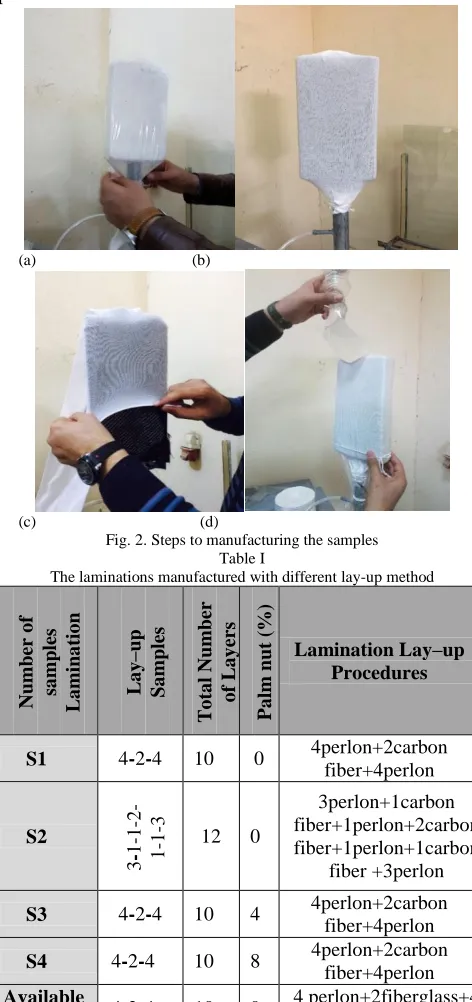
Four samples for second group of composite material will be tested in order to assess their properties. To manufacture the samples; a gypsum mold was placed on a stand and was connected to a vacuum device with a tube as shown Fig. 2a. A layer of (PVA) was then put on the mold. Perlon and carbon fibers and fiberglass were put according to the lamination lay-up as depicted in Table I and shown in the Figs. 2b and 2c. The top end was covered by an outer layer of (PVA) and left opens for resin supply as shown Fig. 2d. The vacuum device was kept operating until all air between layers was removed. After composite material warms up and becomes hard the final product was removed from the mold in order to prepare the specimens for standard mechanical tests.
(a) (b)
(c) (d)
Fig. 2. Steps to manufacturing the samples Table I
The laminations manufactured with different lay-up method
Numb er o f sa mp les L a min a tio n L a y –up Sa mp les T o ta l N um ber o f L a y er s P a lm nu t (%) Lamination Lay–up Procedures
S1 4-2-4 10 0 4perlon+2carbon
fiber+4perlon S2 3 -1 -1 -2 -1 -1
-3 12 0
3perlon+1carbon fiber+1perlon+2carbon fiber+1perlon+1carbon
fiber +3perlon
S3 4-2-4 10 4 4perlon+2carbon
fiber+4perlon
S4 4-2-4 10 8 4perlon+2carbon
fiber+4perlon Available
[44] 4-2-4 10 0
4 perlon+2fiberglass+4 perlon
II.2. MECHANICAL PROPERTIES a. Tensile Tests
Standard tensile test specimens were cut from the final product according to the American society for testing and materials (ASTM) D638 [6], Three specimens were cut for each lamination at the workshop using a computer numeric control (CNC) machine as shown in Fig. 3.
Fig. 3. Specimen for tensile test (all dimensions in mm)
b. Flexural Test
Three specimens from second suggested material were used as specimens of flexural test to find the average bending modulus of elasticity to prepare the fatigue test specimens. The test was carried out using testometric machine. The size of the samples was selected according to the machine's manual as shown in figure Fig. 4.
Fig. 4. The dimensions for bending specimen (all dimensions in mm)
c. Fatigue Test
Fatigue machine (HSM20) was used in this test. The size of the samples was selected according to the machine's manual as shown the Fig. 5. The test was carried out on eight specimens for second suggested lamination. To find the values of the alternating stress (σa), Eq. (1) can be used as follows, [7]: σa=1.5 Eb ℓ2∗ta∗δ (1)
Fig. 5. Fatigue specimen stander dimension
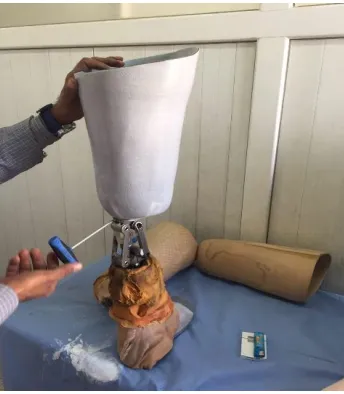
II.3. SOCKET MANUFACTURING AND TESTING a. Manufacturing
Fig. 6. Connected socket with knee joint
b. Measuring Interface Pressure
The pressure between the socket and the stump was found by the means of the F-Socket sensor as shown in Fig. 7. The pressure was measured by placing the sensors onto four regions of the residual limb (Anterior, Lateral, Posterior, and Medial). These forces are produced during the walking of the patient. The patient was a male, age 27 years, weight 80 kg, length 180 cm, type of amputation TK, and the side of amputation is the right leg. The data resulted from this test are to be used later as an input data for ANSYS program.
Fig. 7. Position of sensor of pressure on patient with TK prosthesis
III. ANALYTICAL ANALYSIS
One of the chief purposes of a lower-limb socket, is to bear the weight of the amputee’s,body. The forces created during locomotion in addition to the weight of the amputee are transferred from the, bone to the socket through the tissue and skin of the extremity. A part of vertical force is supported by
the vertical component. Due to the fact that the effective, conical angle of the prosthetic socket shell, is very little, the chief component, of the normal force acts in horizontal, direction and presses the skin towards radial, direction. Friction causes a force acting in the tangential direction to the skin, assists with holding the prosthesis in its position and prevent possible detachment while swinging, phase of gait and supports the body weight during the support phase. For the sake of understanding the action of friction between a stump and a prosthetic socket, a simplified, model has been, established. Two assumptions, were made:
i. A conical shape of the limb’s soft tissue would be produced due to the compression exerted by the prosthetic socket.
ii. The internal bone was considered of cylindrical shape as shown in Fig. 8.
iii. A consideration was made in this model of that these tissues are to be taken as elastic materials and act as a spring 𝑭 = 𝑲𝒅. A “normal” one is considered to mimic support force caused by soft tissues’ normal compression against the skin surface, and, a “parallel” one representing the force produced as a result of shearing or stretching in a direction parallel to the interface [40]. Further consideration were taken that the material was considered as homogeneous, isotropic and linear. Normal and parallel constants of springs,𝑲𝒏𝒂𝒏𝒅𝑲𝒔 can be found from:
Kn=EsA t (2) Ks=GAt (3)
Where G is the shear modulus [G = Es/2(1 + υ)], Es is the Young’s modulus of soft tissue, t the average thickness of soft tissue, υ is the Poisson ratio, A is the area supporting surface of skin which can be calculated from:
A = π L Du+ Dl
2 (4)
Stresses predicted. The average pressure and shear stress acting on the extremity surface is given by:
σ = Kn
A (dno+
W sin Ɵ
Kn sin2Ɵ+Ks cos2Ɵ ) (5)
Fig. 8. Simplified residual limb model [8] And,
τ =Ks
A(−
Kn
KsdNotan Ɵ +
W cos Ɵ
Kn sin2Ɵ+Ks cos2Ɵ ) (6)
It has beenshown that the damage of tissues relies on the resultant of shear and normal stresses σc. This resultant can be obtained from the Eq. (5) and Eq. (6) gives [8].
σc= √σ2+ τ2 (7)
III.1. CASE STUDY
The analysis was conducted using some typical values for, the geometric and mechanical, properties related, with the limb/prosthetic socket: upper, diameter (𝐷𝑢= 145mm), lower, diameter ( 𝐷𝑙= 135mm), height (H = 40mm), average tissue, thickness t = 20 mm, conical, angle Ɵ = 7.120, coefficient of friction µ = 0.4, Poisson’s ratio υ = 0.5, Young modulus, soft tissue E = 100 kPa [41], and force (w= 800N).
vertical, stiffness 88.649 N/mm at, weight of 800 N acting on bone. The minimum displacement of the normal spring𝒅𝒏𝒐is 14.065mm. The average interface, shearing and normal stresses are 34.646 kPa and 86.6149 Kpa, respectively. The shear and normal stresses resultant equals to 93.28 kPa.
III.2. NUMERICAL ANALYSIS FOR TK PROSTHETIC SOCKETS
The finite element method (FEM) provides a numerical solution for complicated problems including complex geometrical boundaries and non-linear material properties. In this work, ANSYS workbench 14.5 software was used as a numerical tool to find the effect of the fatigue, the stress distribution contours, directional deformations, and the safety factor.The analysis done using ANSYS workbench involves, constructing the geometry and meshing, applying the boundary conditions, loading conditions, and executing the program. Finite element model of the socket was built according to the real geometrical dimensions of the amputee’s stump. The real dimensions of the socket were measured. These dimensions were used later on to draw the model using SolidWorks software (Version 2015). The resulted model was then exported to ANSYS workbench 14.5.
III.3. ANALYSIS TYPE AND APPLYING LOAD
The term ‘load’ refers the boundary conditions including constraints, supports and any other external and internal loads. The load is fed to ANSYS and the fixed support is assigned at the adapter of the socket. Simultaneously, the interface pressure is the pressureoccurring between the socket and the patient’s stump during the locomotion. Fig. 9 depicts the position of pressure distributions of the present experimental
case study, the values of this pressure is obtained from two cases; the first case is obtained from the experimental part (F-socket sensor) and the second one is from the analytical part. The pressure for the analytical part is represented in Fig. 10.
Fig. 9. Locations of pressure forces on the model for the experimental part (F-Socket)
Fig. 10. Applying the locations of pressure forces on the model for the analytical part
IV. RESULT AND DISCUSSION IV.1. TENSILE TEST RESULTS
Table II
Mechanical properties of socket samples
Material Thickness
(mm)
Ultimate stress
𝝈 𝒖𝒍𝒕 (Mpa)
Modulus of elasticity
(E)(Gpa)
S1 3.7 92.03 1.773
S2 3.9 148.2 3.95
S3 4 96.1 2.113
S4 4.1 99.5 2.5
Available
model 4.1 33.65 0.941
IV.2. FATIGUE AND FLEXURAL TEST RESULTS
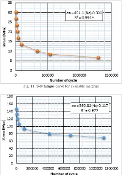
The flexural test has revealed that the average value of bending modulus of elasticity was (8.25 GPa). The stress versus the number of cycles from fatigue testing for available and suggested sockets are depicted in Fig. 11 and Fig. 12 respectively. For material S2 the calculation of stress endurance limit (σe) is equal to 71.6 MPa. While the available model the stress endurance limit (σe) is equal to 7.05 MPa.
Fig. 11. S-N fatigue curve for available material
Fig. 12. S-N fatigue curve for suggested material S2
IV.3. INTERFACE PRESSURE TEST RESULTS
After carrying out the tests and obtaining the results of interface pressure for these regions. These regions were divided to three parts: upper, middle and bottom as shown in
Fig. 13 for the posterior region. The load exerted on the stump when it is loaded normally is distributed non-uniformly. The positions and the pressure on the inner sides of the socket are listed in Table III and Table IV summarized values of interface pressure were calculated analytically in theoretical part. These values of interface pressure are to be imported to ANSYS in a further step in order to be used as boundary conditions.
Fig. 13. Interface pressures distribution in the pressure sensor for the anterior area.
Table III
Values of interface pressure (F-Socket) for the prosthetic socket Socket
Regions
Sensor Positions
Interface Pressure (KPa) Anterior
A 114.6
B 121
C 111.8
Lateral
J 74.2
K 56.6
L 51.5
Posterior
D 103
E 101.5
F 84
Medial
G 39
H 52.4
I 47.1
Table IV
Values of interface pressure (theoretical) for the prosthetic socket
SocketRegions Upper Middle Lower
Interface
Pressure (kPa) 70.6 79.22 90.17
IV.4. FINITE ELEMENT RESULTS
The static and fatigue properties of prosthetic socket were investigated using finite element method. Two cases of socket were implemented by using ANSYS, the first case was the available prosthetic socket material, and the second one was the suggested prosthetic socket.
contours for the experimental and analytical values of the interface pressure values for the available socket.
The analysis of deformation allowed to knowthe values of total directional deformation and their positions in the socket. From this study, it can be observed that the highest value of total deformation in available socket, while the lowest value in the suggested socket for both parts. Fig. 16 represents the total deformations for suggested composite material (S2) for experimental and theoretical. The values of total deformations are 3 mm and 2.63 mm for experimental and theoretical respectively. While Fig. 17 represents the total deformation for the available prosthetic socket for experimental and theoretical. The values of total deformations are 8.68 mm and 7.62 mm for experimental and theoretical respectively.
a. The interface pressure values are measured experimentally
b. The interface pressure values are calculated analytically Fig. 14. Von-Mises stress for suggested prosthetic socket (S2)
a. The interface pressure values are measured experimentally
b. The interface pressure values are calculated analytically Fig. 15. Experimental Von-Mises stress for available socket
b. The interface pressure values are calculated analytically Fig. 16. Total deformation for suggested prosthetic socket (S2)
a. The interface pressure values are measured experimentally
b. The interface pressure values are calculated analytically Fig. 17. Total deformation for available prosthetic socket
The minimum safety factors obtained for the suggested prosthetic socket, for experimental and analytical parts are equal to 4.832 and 4.932 respectively, Fig. (18) showed these results for the suggested prosthetic socket. While for the available prosthetic socket; the minimum safety factors were 0.611 and 0.625 for experimental and analytical parts respectively, as shown in Fig. 19.
a. The interface pressure values are measured experimentally
b. The interface pressure values are calculated analytically Fig. 18. The minimum equivalent safety factor for suggested prosthetic socket
b. The interface pressure values are calculated analytically Fig. 19. The minimum equivalent factor of safetyfor the available socket
V. CONCLUSIONS
From the previous discussion, the following conclusions can be summarized as follows:
1. Increasing the number of layers of carbon and perlon fiber had a positive effect on increasing the strength since theypossess superior tensile properties.
2. The suggested model (S2) has a perfection in both, the ultimate stress and modulus of elasticity, by 61.03% and 123.16%, respectively, when compared with the available design.
3. As a result of fatigue test the suggested design of composite material sequence has an improvement in the stress endurance limit by 915 % with respect to the available material.
4. It can be noticed that deformations are at their minimum values for the suggested design. That can be justified by the fact that the suggested design has superior mechanical properties with respect to the available material.
5. There was an increase in the value of minimum factorof safety in suggested material as compared with the available material from 0.611 to 4.832.
Symbols
A : Area supporting surface of skin (m2)
Dl : Lower socket diameters side of the support surface (mm)
Du : Upper socket diameters side of the support surface (mm)
dno : Pre-compressive displacement of the normal spring (mm)
Eb : Bending modulus of elasticity (GPa) Es : soft tissue’s modulus of elasticity (kPa) G : modulus of rigidity (kPa)
Kn : Normal spring constants (N/mm) Ks : Parallel spring constants (N/mm) L : Length limb contacts with socket ℓ : Length fatigue specimen (mm)
Dl : Lower socket diameters side of the support surface (mm)
t :Average thickness of soft tissue (mm) ta : Average thickness for fatigue specimen (mm) W :Vertical force (weight)
Ɵ : Conical angle (degree) δ : Deflection (mm)
σ : Average pressure acting on the extremity surface (kPa) σc : Resultant of shear and normal stresses (Mpa)
σe : Stress endurance limit (Mpa)
τ : Shear stress acting on the extremity surface (Kpa)
REFERENCES
[1] Nellis, N. and J. M. Van De Water, “Through-the-Knee Amputation: an Improved Technique, ” The American surgeon 68(5): 466, 2002. [2] M.J. Jweeg, K.K. Resan, and M. Tarig, “Study of Fatigue Creep
Interaction in a Below Knee Prosthetic Socket,” ASME International Mechanical Engineering, Nov. 9-15, Houston, Texas, USA, 2012. [3] M.J. Jweeg, A.S. Hammood, and Muhannad Al-Waily, “Experimental
ans Theoretical Studies of Mechanical Properties for Reinforcement Fiber Types of Composite materials,” International Journal of Mechanical and Mechatronics Engineering, IJMME-IJENS, Vo. 12, No. 4, pp. 62-75, 2012.
[4] A.M. Takak, M.J. Jweeg, and S.M. Abbas,Characterization of Materials Used in Manufacturing the Ankle Foot Ortheses,” International Journal of Energy and Environment , Issue on Applied Mechanics Research, Vol. 8, Issue 4, pp. 291-298, 2017.
[5] J.S. Chiad, “Study the Impact Behavior of the Prosthetic Lowe Limb Lamination Materials due to Lower Velocity Impactor, “ Proceeding of the ASME, 12th Biennial Conference of Engineering System Design and Analysis, June 25-27, Copenhagen, Denmark, 2014.
[6] American Society for Testing and Materials International, “Standard Test Method for Tensile Properties of Plastics, D 638, 2000.
[7] Alternating Bending Fatigue Machine Instruction Manual HSM20. [8] Zhang, M., et al., “Frictional Action at Lower Limb/Prosthetic Socket
Interface,” Medical Engineering & Physics, ” 18(3): 207-214, 1996 [9] Zhang, M. et al., “Estimating the Effective Analysis of Effects of

![Fig. 8. Simplified residual limb model [8]](https://thumb-us.123doks.com/thumbv2/123dok_us/1353055.1643973/4.612.317.564.316.463/fig-simplified-residual-limb-model.webp)