Dual Winding Concurrent Machine: Performance and Parametric Analysis
K.Muthukumar
1, J.Ikramullah
2and V.Chandrasekaran
31,2, 3
Department of EEE, Sri Krishna College of Engineering and Technology, Coimbatore, Tamilnadu, India. Email: [email protected], [email protected]
Article Received: 22 September 2017 Article Accepted: 25 December2017 Article Published: 12 January 2018
1. INTRODUCTION
Conventional induction motor consists of only one set of winding in its stator and DWIM consists of two sets of
windings in the same stator. A three phase supply is applied to one of the stator windings, a revolving magnetic
field is developed in the air gap and this field is shared by both windings. Two separate windings with displaced
angle between them are provided in the same stator for the improvement in efficiency. The behavior of an alternator
with two three phase stator windings displaced by an angle is analyzed by means of an orthogonal transformation
(Fuchs1974). Weber (1992) represented a dual stator induction motor for energy conservation which consists of
two sets of RUN windings. Out of two sets of windings, one set of RUN winding is energized to have sufficient
MMF to meet the reduced mechanical load, thereby the flux density in stator core reduces, reduced eddy current
losses and copper losses. Depending on the shaft load of the machine, second set of RUN winding is excited
through a power source.
2. DESIGN OF DOUBLE WINDING INDUCTION MOTOR
In a double winding induction motor, when one of the windings is connected to a three phase supply, a revolving
magnetic field of constant magnitude is developed in the air gap. This is utilized by both the stator windings to work
as induction motor to meet mechanical load while, a three phase EMF is induced in the second set of winding to
which electrical load can be connected to work as an Induction alternator.
3.
REPRESENTATION OF DWIM
Razik (2006) explained that the stator windings of double winding induction motor can be arranged with different
shift angles .In DWIM, shift angle of 60 degrees or zero degrees are the best choice. In the proposed model, to A B S T R A C T
Synchro machines are generally employed for constant speed applications. An attempt is made in this project to improve the efficiency and power factor of synchronous machine and also to conserve energy. A 3kw, 415V, 1500 rpm Double winding synchronous machine (DWsyM) has been designed, fabricated and tested. The stator consists of two sets of 3 phase winding in the same core. Since the machine always runs at synchronous speed the terminal voltage at the secondary winding is always maintained constant. A separate DC source is required to excite field winding of synchronous machine. There are various methods exciting the field winding. In double winding synchronous machine excitation process become simple compared to any other methods. One of the 3 phase stator winding is energized by a 3 phase supply. Separate DC source is not required for field winding. Load tests with various combinations of electrical and mechanical loads have been conducted. Experiment results prove improvement in the efficiency and power factor to great extent compared to induction and reluctance motor. Since the load connected to second set of winding is not dependent on separate supply, the power tapped from this winding is considered as energy conservation. This type of machine can be employed where the machine is expected to run continuously. In addition to performance improvement, energy conservation is also obtained.
obtain optimum utilization, both the windings are placed with zero degree phase angle displacement between them
and the representation of proposed DWIM is shown in Figure3.1.
Figure.3.1 Double Winding Induction Motor
Design Considerations
Design of the double winding induction motor is affected by various constraints such as thermal limit, over load
capacity and utility of stator slots. Energy conserving double winding induction motor is ideal to be used for low
power operations due to the limitation in thermal insulation value. The value of air gap flux density is large which
determines large overloadcapacity.Useofsemi-enclosedslotsresultsinsilentoperation.The stator of DWIM consists
of two sets of stator windings placed in the same slot and therefore slot utility is increased. Slot utility factor for
designed DWIM is 43.3%whereas for a conventional induction motor, it is about 29%.
Design of stator
Design procedure is presented for a 3kW, 415V, 50Hz, Double Winding Induction Motor. Electrical loading,
magnetic loading, efficiency and power factor of the machine are chosen as given below:
Flux density in the stator core Bav = 0.44Wb/m2
Electrical loading = 18000ac/m
Efficiency = 80% Power factor = 0.85
Winding factor Kw = 0.9
Output Co-efficient C0= 11xBav x Kw xacx10-3 = 11x 0.44x0.9x18 = 83.2
kVA output of the motor Q = 3/ 0.8x0.85 = 4.41kVA
The product of the diameter and the length of the core
For good overall design ratio
Length of core L = 0.785D
Diameter of the core = 0.139m
Length of the core = 0.11m
DWIM presented here consists of two sets of identical coils in the same stator core. Hence the design of one set is
similar to the other.
Stator voltage per phase Vph = 240V
Flux per pole m = (BaxDxL)/ P = 5.28mWb
Turns per phase Tph = Vph/(4.44x50x 5.28x 10-3x0.9) = 228turns
Slot per pole per phase =3
Number of stator slots =36
Slot pitch =D/Ss = x0.139x103/36 = 12mm
Total stator conductors for each winding = 3x2x228 = 1368conductors
Conductors per slot for each winding = 1368/36 = 38
Stator current per phase is = 3x10³/3x240x0.8x0.85 = 6.1A
18SWGenameledcoppercoilischosenforthewinding
Diameter of the conductor=1.22mm
Area of Stator conductor=1.17mm2
Current density = 6.1/1.17 = 5.21A/mm2
Area of conductors per slot = 1.17x76 = 88.92 mm2
Area of each slot = 205mm2
4. PERFORMANCE OF DWIM
One stator acts as a motor and the other as a generator. By controlling the voltage supplied to the generator winding,
the rotor speed can be adjusted. One of the stator winding of DWIM is connected to a three phase supply; a
revolving magnetic field is developed in the air gap. With respect to first winding, this field interacts with rotor
conductors and develops torque to meet mechanical load, where as a three phase EMF is developed in second set of
winding to which an additional electrical load can be connected. The main scope of concept is energy conservation,
efficiency and power factor improvement at reduced mechanical load of DWIM.
Load test with Electrical and Mechanical loads
In the proposed DWIM, both stator windings are of identical nature. In order to obtain performance characteristics
as conventional induction motor, one of the windings is connected to a three phase supply and other set of winding
is left free .Load test has been carried out with brake drum arrangement and electrical load on second set off
winding to study the performance of machine. Experimental set up with both electrical and mechanical loading is
shown in Figure 4.1.Table 4.1shows the reading observed considering one set of winding to operate the machine as
induction motor to meet the mechanical load and the second set of winding is unloaded. Efficiency and power
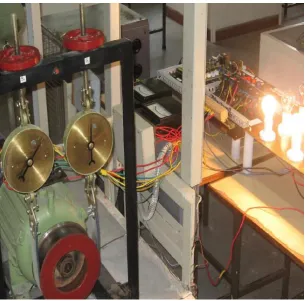
factor characteristics are shown in Figure4.2. The maximum efficiency of the machine is 83.6% and the
corresponding power factor is 0.63.
Table 4.1 Conventional load test In p u t v o lt a g e Li n e c u rr e n t In p u t p o w er (W ) S p ee d in rp m T o rq u e in N m O u tp u t p o w er (W ) % E ff ic ie n c y P o w e r f ac to r % S li p
415 2.5 480 1466 0 0 0 0.27 2.3
415 3.0 720 1458 3.6 549 76.3 0.33 2.8
415 3.5 1240 1448 6.4 968 78.1 0.49 3.5
415 4.0 1680 1442 9.1 1368 81.4 0.58 3.9
415 4.5 2040 1438 11. 3
1705 83.6 0.63 4.1
415 5.0 2250 1426 12. 2
1814 81.6 0.63 4.9
415 5.5 2880 1416 15. 7
2320 80.6 0.73 5.6
415 6.0 3360 1408 18. 1
2672 79.5 0.78 6.1
Figure 4.2 Efficiency and power factor Characteristics (DWIM)
V o lt a g e( V ) Li n e c u rr e n t( A ) In pu t po w er (W ) S p ee d (r p m ) T o rqu e( N m ) M e ch an ic a l o u tpu t (W ) El e ct ri ca l o u tp u t( W ) T o ta l o u tp u t( W ) % E ff ic ie n c y P o w e r f a ct o r % S li p
415 2.4 840 1480 0 0 720 720 85 0.49 0.93
415 3.0 1380 1470 2.3 354 720 1074 78 0.64 1.60
415 4.0 2240 1458 8.0 1220 720 1940 86 0.78 2.80
415 4.5 2760 1452 10. 8
1640 720 2360 85 0.85 3.20
415 5.0 3080 1444 12. 0
1810 720 2530 82 0.86 3.73
415 6.0 3640 1420 14. 7
2185 720 2905 80 0.84 4.93
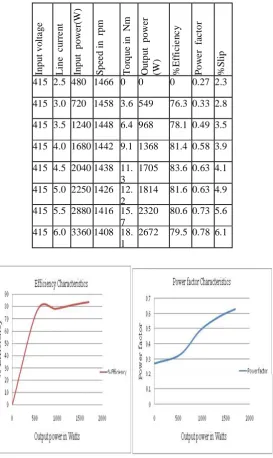
Test performance have been compared with IEC60034-30, it is observed that the standard efficiency for 3kW,
4-pole induction motor is
81.5%, but in tested machine efficiency is 79.9%.DWIM consists of two identical windings, when a three phase
415V supply is applied to one winding, the same magnitude of 415V is induced in second winding .A lamp load is
used to test the machine whose power factor is unity. Table 4.2 shows the reading observed with1A electrical load
on second set of winding in addition to the mechanical load. Efficiency and power factor characteristic are shown in
Figure4.3.The maximum efficiency of the machine is 86% and the corresponding power factor is 0.78.
Table 4.2 Mechanical load with1A Electrical Load
V o lt a g e( V ) Li n e c u rr e n t( A ) In pu t po w er (W ) S p ee d (r p m ) T o rqu e( N m ) M e ch an ic a l o u tpu t (W ) El e ct ri ca l o u tp u t( W ) T o ta l o u tp u t( W ) % E ff ic ie n c y P o w e r f a ct o r % S li p
415 2.4 840 1480 0 0 720 720 85 0.49 0.93
415 3.0 1380 1470 2.3 354 720 1074 78 0.64 1.60
415 3.5 1840 1468 5.6 859 720 1579 86 0.73 2.13
415 4.5 2760 1452 10.8 1640 720 2360 85 0.85 3.20
415 5.0 3080 1444 12. 0
1810 720 2530 82 0.86 3.73
415 6.0 3640 1420 14. 7
2185 720 2905 80 0.84 4.93
Figure 4.3 Efficiency and power factor with 1A Electrical load (DWIM)
Table 4.3 shows the reading observed with 1A electrical load with capacitor across the load and efficiency and
power factor characteristics is shown in Figure 4.4.When a capacitor of 20µF is included across the load, the
maximum efficiency increased to 85.8% and the corresponding power factor is improved to 0.94.
Table 4.3 Mechanical load with 1A Electrical Load and Capacitance
In pu t V o lt ag e Li n e C u rr e n t( A ) In pu t Po w er (W ) S p ee d in rp m T o rqu e N m M e ch an ic a l O u tp u t( W ) El e ct ri ca l O u tp u t( W ) T o ta l O u tp u t( W ) % E ff ic ie n c y P o w e r F a ct o r
415 2.7 1800 1440 6.6 994 480 1474 81.8 0.93
415 3.1 2080 1435 8.0 1207 520 1727 83.0 0.93
415 3.6 2440 1435 10.5 1573 520 2093 85.8 0.94
415 4.1 2780 1420 12.4 1838 520 2358 84.8 0.94
415 4.7 3160 1410 14.2 2097 520 2617 82.8 0.94
Figure 4.4 Efficiency and power factor with 1A load and capacitor (DWIM)
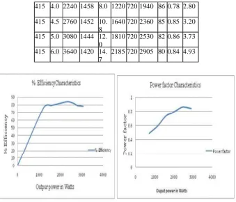
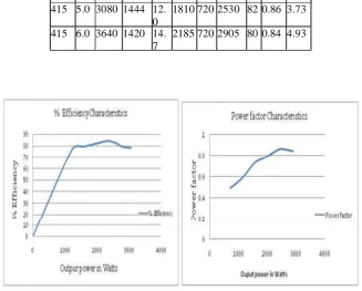
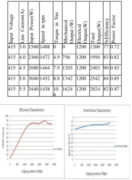
Table 4.4 shows the reading observed with 2Aelectrical load on the second set of winding in addition to the
mechanical load and the corresponding performance characteristics is shown in Figure 4.5.The maximum
efficiency of the machine is84% and the corresponding power factor is 0.85.
Table 4.4 Mechanical Load with 2A Electrical Load
In p u t V o lt a g e Li n e C u rr e n t( A ) In p u t P o w e r( W ) S p ee d in rp m T o rq u e i n N m Me ch an ical Ou tp u t ( W ) El e ct ri c al O u tp u t( W ) T o ta l O u tp u t( W ) % E ff ic ie n cy P o w e r F a ct o r
415 3.0 1560 1488 0 0 1200 1200 77 0.72
415 4.0 2360 1472 4.9 756 1200 1956 83 0.82
415 4.5 2680 1464 7.9 1203 1200 2403 90 0.83
415 5.0 3040 1452 8.8 1342 1200 2542 84 0.85
415 5.5 3440 1438 10. 8
1624 1200 2824 82 0.87
Table 4.5 shows the reading observed with 3Aelectrical load on the second set of winding in addition to the
mechanical load and the corresponding performance characteristics is shown in Figure 4.6.The maximum
efficiency of the machine is 92% and the corresponding power factor is 0.91.
Table 4.5 Mechanical load with 3A Electrical Load
In p u t V o lt ag e Li n e C u rr e n t( A ) In p u t P o w er (W ) S p ee d in rp m T o rq u e N m M e ch an ic a l O u tpu t( W ) El e ct ri ca l O u tp u t( W ) T o ta l O u tp u t( W ) % E ff ic ie n c y P o w e r F a ct o r % S li p
415 3.7 2480 1474 0 0 2125 2125 86 0.93 1.7
415 4.0 2640 1460 2.0 301 2125 2426 92 0.91 2.7
415 4.5 3120 1452 3.7 715 2125 2840 91 0.96 3.2
415 5.0 3480 1440 6.6 1035 2125 3160 90 0.97 4.0
415 5.5 3920 1430 9.4 1410 2125 3535 90 0.99 4.7
415 6.1 4360 1426 11. 6
1728 2125 3853 88 099 4.9
Figure 4.6 Efficiency and power factor with 3A Electrical load (DWIM)
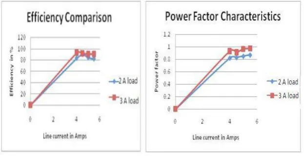
Table 4.4 corresponds to the reading with 2Aelectrical load in the second winding and Table 4.5 shows the reading
with 3A electrical loading the second winding. The efficiency and power comparison is shown in Figure 4.7. Main
focus of this concept is to improve efficiency and power factor when the machine is lightly loaded with mechanical
output. When operated as a conventional induction motor for a load current of 3A, efficiency is 76.3% and power
factor 0.33.For the same load current, electrical load of 720W is added in the second winding and hence efficiency
is improved to 78% and power factor to 0.64.With a capacitor of 20µF across the load, efficiency is improved to
Figure 4.7 Efficiency and power factor comparison for 2A and 3A (DWIM)
5. CONCLUSION AND FUTURE WORKS
A 3 kW, 3- phase, 4- pole, 1500 rpm, 415 V Double Winding Induction motor has been tested. When the machine
is operated as conventional induction motor, the maximum efficiency and power factor are 76.33% and 0.33. When
an electrical load is connected in the second winding, the efficiency and power factor are improved to 83% and
0.93. By utilizing the electrical output from the second set of winding, dependency on separate supply to the
connected load to this winding is reduced. The Double Winding Induction Motor can be employed, where the
induction motors run continuously like in textile industries and manufacturing units. As a future scope, a DC
shunt motor is coupled with this double winding induction motor to act as a dual alternator machine to find out
regulation and embedded control systems drives are to be used. The output power from the machine can be used for
charging the light loads and power loads.
REFERENCES
[1] Hubert.Razik, Abder rezak Rezzoug, Djafar. Hadiouche “Modeling and analysis of Dual – Stator Induction
Motors”, IEEJ Transactions Industrial Applications, Vol. 125, 2005 pp 1093-1104.
[2] Prof. V. Chandrasekaran, “Design and Development of Three Stator Winding Induction Motor”, International
Journal of Electrical Engineering, Vol.4, No.3, pp. 341-351, 2011.
[3] Prof. V. Chandrasekaran, “Double Winding Induction Motor- an approach for Improvement of Power Factor
and Efficiency”, European Journal of Scientific Research, Vol.66,No.2, pp 262-273,2011.
[4] Harold J. Weber, “A.C. Induction motor energy conserving power control method and apparatus” US Patent
4806838, February 21, 1989.
[5] Alfredo Munaz-Garcia, Thomas A.Lipo, “Dual stator winding Induction Machine Drive”, IEEE Transactions
on Industry Applications Vol. 36, Sep/Oct 2000 pp 1369 – 1379.
[6] C. Thanga Raj, S. P. Srivastava, PramodAgarwal, “Energy Efficient Control of Three-Phase Induction Motor -
[7] P.L. Alger, E.H.Freiburghouse and D.D.Chase, “Double windings for flexible alternators”, AIEE
Transactions, Vol.49, January 1930, pp 226 – 244.
[8] Jan šlamberger, Mario vražić, Peter VIRTIČ, “Comparison of single- and double-layer windings in an axial
flux permanent-magnet synchronous machine”, Przegl Ąd Elektrotechniczny, ISSN 0033-2097, R. 90 NR 12/2014.
[9] Adrian D.Martin, Dănuț l.vitan, lucian n. tutelea, Nicolae muntean, “Double Stator Winding Induction