International Journal of Emerging Technology and Advanced Engineering
Website: www.ijetae.com (ISSN 2250-2459,ISO 9001:2008 Certified Journal, Volume 3, Issue 4, April 2013)
719
Investigation of Seepage Paths in Left Abutment of Bidvaz
Dam Using Tracing Technique
Sepideh Nasseh
1, Mohammad Ghafoori
2, Naser Hafezi Moghaddas
3, Gholam Reza Lashkaripour
4 1Ph.D. student, 2,4Professor, 3Associate professor, Engineering Geology, Faculty of Sciences, Ferdowsi University of Mashhad, Mashhad, Iran
Abstract—In this study, seepage phenomenon through left abutment of Bidvaz earth-fill dam with 66m height is investigated. The Bidvaz is constructed in order to control the floods for using in agriculture and fish cultivating as well as supplying a portion of drinking water for Isfarayen city, NE of Iran. The dam site consists of two different alluvial and rocky parts. The alluvial part is sealed by a plastic concrete cut-off wall while a grout curtain is constructed in the rocky area. This research deals with applying tracing technique in order to evaluate the effectiveness of the grout curtain. To meet this aim, two different types of dye tracers, Uranine and Rhodamine B are employed. These tracers are injected into injection boreholes and then sampling is done through sampling points. Based on the results, the occurrence of seepage in the left abutment of Bidvaz dam is confirmed. The results show that some parts of the grout curtain are not acting effectively to control seepage.
Keywords— seepage, tracing technique, Uranine, Rhodamine B, Bidvaz dam.
I. INTRODUCTION
Building dams in karstic regions which generate huge resources of water is inevitable. On the other hand, these regions usually include openings and caves which may cause seepage in dams. Different studies on seepage problems in dams have been undertaken on the Salman Farsi dam in Iran (Fouladi and Golshan, 1999), the Kafrein dam in Jordan (Malkawi and Al-Sheriadeh, 2000), the Lar dam in Iran (Uromeihy, 2000; Djalaly, 1988; Ghobadi, 1986), the Kalecik dam in Turkey (Turkmen, 2003; Turkmen et al., 2001) and the Shahid Abbaspour dam in Iran (Ghobadi et al., 2005). In order to investigate such seepage paths in dams, tracing technique is so common and useful. Tracers are substances that are added to water in order to determine its spatial and temporal distribution. Tracers are divided into insoluble (solid) and soluble substances. Soluble tracers include dyes, radioactive isotopes, optical brighteners, and inorganic salts. Undoubtedly soluble tracers are preferred over the insoluble ones because of considerably better tracing characteristics such as solubility, potential of detection in high dilution, and simple sampling.
Dye tracers are most often used for investigation of underground water links in karst. In addition to the frequently used Na-fluorescein (Uranine), other tracers used are Rhodamine B, Rhodamine WT, Eozine FA, salt (NaCl), Congo red, Fuksin, etc.
The most successful karst water tracer at the present time is sodium fluorescein (C10H10O5Na2) (Milanovic, 2004).
This research deals with the investigation of possible seepage paths in Bidvaz dam especially in the left abutment.
II. DAM CHARACTERISTICS
Bidvaz dam is located in the northeast of Isfarayen city, NE of Iran. The dam construction activity finished in 2003 and the dam impounded in the same year. This dam is an earth-fill one with an inclined clay core which is constructed on an alluvial foundation. It has a height of 66m and an efficient reservoir volume of about 32000000m3. Its crest is 104m long and 11m wide. The dam region consists of two different parts; alluvial part and rocky part. The alluvial part is sealed by a plastic concrete cut-off wall while a grout curtain is constructed in the rocky area. The main goals of constructing Bidvaz dam are manipulating the run-off water and specifically river floods of Isfarayen plain in order to use in agriculture and fish cultivating as well as supplying a portion of Isfarayen drinking water.
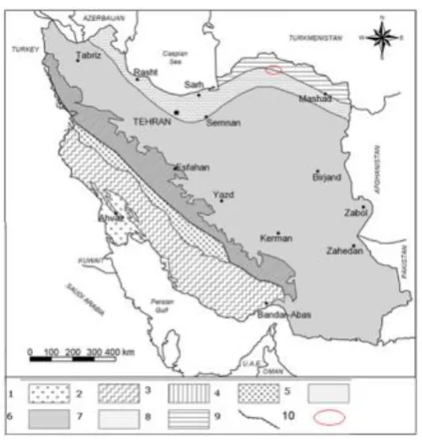
Considering the geological classification of Iran, the Bidvaz dam region is situated on the southern boundary of Kopet Dagh zone (Figure 1). The dam axis is located on the northern limb of an anticline where the Bidvaz River is flowing with a trend of N-S and a dip of around 1.4% toward south. The river valley is made up of the late Cretaceous Tirgan limestone formation. Tirgan formation builds the southern and northern abutments of the reservoir as well; although in the northern abutment, the layers of marl, conglomerate and red sandstone of Pesteligh formation overlay the Tirgan limestone. The youngest recent alluvium in the reservoir has been resulted from erosion of these formations.
III. MATERIALS
International Journal of Emerging Technology and Advanced Engineering
Website: www.ijetae.com (ISSN 2250-2459,ISO 9001:2008 Certified Journal, Volume 3, Issue 4, April 2013)
[image:2.595.49.288.247.496.2]720
Uranine is a reddish-brown powder that turns vivid yellow-green in water, it is photochemically unstable, and loses fluorescence in water with pH less than 5.5. Uranine in aqueous solution occurs in cationic, neutral, anionic and di-anionic forms, making its absorption and fluorescence properties strongly pH dependent (Sjoback et al., 1995). This tracer has no certain smell and has proven to be non-hazardous for human beings and animals specifically in concentrations which are employed in tracing tests (Benischke, 2001).Figure 1. Geological map of Iran and location of the study area:
(1) Mesopotamian zone and Khuzestan plain, (2) low folded zone, (3) high folded zone, (4) thrust zone, (5) Sanandaj-Sirjan zone, (6) central Iran tectonic units, (7) Khazar Talesh Ziveh and Makran zone, (8) Kopet Dagh zone, (9) Zagros thrust fault, (10) The study
area.
The other dye tracer used in this research is Rhodamine B (C28H31N2O3Cl; diethyl ammonium chloride) which is a highly water soluble. It is found as a reddish violet powder. It is a well-known water tracer fluorescent (Richardson et al., 2004). It is harmful if swallowed by human beings and animals, and causes irritation to the skin, eyes and respiratory tract (Rochat et al., 1978). The carcinogenicity, reproductive and developmental toxicity, neurotoxicity and chronic toxicity towards humans and animals have been experimentally proven (The EFSA Journal, 2005; Shimada et al., 1994; McGregor et al., 1991; Mirsalis et al., 1989; IARC, 1987; Kornbrust and Barfknecht, 1985). Therefore, it is not recommended in resources that may be used as drinking water.
After deciding about the type of tracer, the optimal quantity of dye should be determined. In this regard, different specialists proposed formulas for the dye quantity considering variable parameters such as the swallow capacity of ponor, the outflow discharge of a spring, the shortest distance between ponor and spring, etc. The main application of these formulas is for determining the approximate quantity of dye to be used in various tests. In this research, Martel equation was employed.
K=L×Q (1)
Where K is the quantity of dye in kilograms, L is the distance between the dye test point and the most remote spring in kilometers, and Q is the total discharge of all springs under observation in cubic meters per second (Martel, 1913).
Using the above equation, 5 Kg of Uranine and 2 Kg of Rhodamine B were employed for injection in two different places.
IV. METHODS
In order to carry out the tracing project in the region with a high percentage of reliability, the following considerations were observed: 1) Three steps of injection, sampling and doing measurements were carried out by three different groups who were not physically in touch. 2) To be sure that the tracer is not trapped in the injection boreholes and it will reach the main paths of water flow, water was injected into the boreholes after the injection of the tracer. 3) The injection team put on the proper cloths and gloves during the injection work. Moreover, they had no contact directly with the tracer material. 4) During the injection work, various barrels and containers were applied. 5) After the work, all clothes and equipments used by the injection team were set on fire and were burnt.
The injection process was done in four steps; field investigation in order to determine the injection as well as sampling points, tracer preparation and preinjection phase, the injection work which itself was done in two different stages and finally sampling stage.
International Journal of Emerging Technology and Advanced Engineering
Website: www.ijetae.com (ISSN 2250-2459,ISO 9001:2008 Certified Journal, Volume 3, Issue 4, April 2013)
721
In order to do preparation, first of all, a certain amount of NaOH for the first stage of injection (Uranine) and a certain amount of alcohol for the second stage (Rhodamine B) were dissolved in the water so that the solubility of the solutions increases. Then the tracer powder as well as water was added to the solutions.A. Injection Work
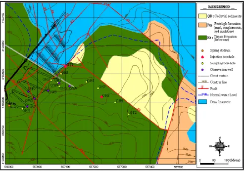
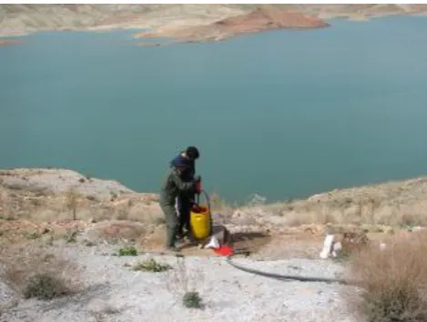
Firstly Uranine solution was injected into the borehole OH8 (Figure 3). Then as long as half an hour, the water
was injected into the borehole in order to lead the tracer solution reach the main flow paths of groundwater in the region.
The tracer was injected into the borehole slowly so that it is not distributed around the injection point. After 2 and half hours following the first step, Rhodamine B was injected into the borehole GT1 (Figure 4).
B. Sampling and Sample Analysis
[image:3.595.54.550.286.632.2]Sampling was done directly through sampling boreholes, springs and downstream drain of the dam. It was carried out by using plastic containers with the volume of 100 mL. All the samples were gathered carefully and then were transferred to the Tehran University laboratory.
Figure 2. Geological map of the dam site as well as the injection and sampling points (Toos Ab consulting engineers, 2009)
This laboratory is equipped to a spectrofluoremeter di monochromatory, Shimadzu-RF5000 model.
International Journal of Emerging Technology and Advanced Engineering
Website: www.ijetae.com (ISSN 2250-2459,ISO 9001:2008 Certified Journal, Volume 3, Issue 4, April 2013)
[image:4.595.308.549.103.639.2]722
[image:4.595.49.290.112.306.2]Figure 3. The injection of Uranine solution into borehole OH8
Figure 4. The injection of Rhodamine B into borehole GT1
V. DISCUSSION
The results of these analyses are in the form of concentration-time diagrams. Based on the diagrams, Uranine is completely observed in the spring, drain, OW7
and OW1 While it shows dispersion in boreholes OH5
and OH7 (Figures 5 to 10).
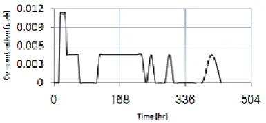
Rhodamine B was not observed in the spring and drain which means effectiveness of grout curtain in this part. Based on figure 11, this tracer was only observed in borehole OH1 behind the grout curtain.
Figure 5. Uranine concentration-time graph of spring
Figure 6. Uranine concentration-time graph of drain
[image:4.595.50.285.329.506.2]International Journal of Emerging Technology and Advanced Engineering
Website: www.ijetae.com (ISSN 2250-2459,ISO 9001:2008 Certified Journal, Volume 3, Issue 4, April 2013)
[image:5.595.52.285.112.283.2]723
Figure 8. Uranine concentration-time graph of OW7
[image:5.595.56.249.587.676.2]Figure 9. Uranine concentration-time graph of OH5
Figure 10. Uranine concentration-time graph of OH7
Figure 11. Rhodamine B concentration-time graph of OH1
A. Water Velocity
For estimating the water velocity in the region, the general equation of velocity can be employed.
Velocity= distance/time (2)
As it is clear, the real flow passes through longer distances rather than the direct path between injection point and sampling point so the length of the direct path should be corrected by multiplying at 1.3 to 1.5 (Thraikill, 1981).
According to the results, Uranine was observed in the sampling points after 15 hours. Moreover, the direct distance between the borehole OH8 (injection point) and
the spring was 330m. Therefore, considering the coefficient of 1.3, the water velocity is estimated about 28.6 m/h which stands in the range of high velocities and turbulent flows. Consequently, the occurrence of seepage in the left abutment of the dam is confirmed.
VI. CONCLUSIONS
In this research, two different types of dye tracers were employed in order to investigate the seepage possibility in Bidvaz dam. Considering all the data, the authors draw following conclusions:
1) Uranine was completely observed in the spring and drain. Therefore, the seepage in the left abutment through Tirgan limestone is confirmed.
2) Considering the estimated velocity of about 28.6 m/h, the existence of turbulent flow in the left abutment was confirmed.
3) Rhodamine B was not observed in the spring and drain which demonstrates the effectiveness of grout curtain in this part.
4) In order to seal the parts that show seepage in this research, it is recommended that grout curtain continues toward south.
Acknowledgment
The authors would like to gratefully thank Pay Kavan Consulting Engineers and Mr. Majid Kamali as well as Mr. Javad Dowlati due to providing the data.
REFERENCES
[1] Benischke R., 2001, Fluorescent tracers in hydrology: principals, instrumentation, physico-chemical properties, analytics Institute for Geothermic & Hydrogeology, Joanneum Research, Graz- Austria.
[2] Djalaly H., 1988, Remedial and water tightening works of Lar Dam, Seizieme Congress das Grandees Barages, San Francisco, USA.
[3] Fouladi C., Golshan S., 1999, Result of field investigation of karstic foundation of Salman Farsi Dam Project (Iran), International Commission on Large Dams (ICOLD), Antalya, Turkey, pp. 19–32.
[4] Ghobadi M. H., 1986, Solubility and grout ability studies of carbonate rock in Lar formation. Master Thesis, Tarbiat Modaress University (in Persian).
[5] Ghobadi M. H., Khanlari G. R., Djalaly H., 2005, Seepage problems in the right abutment of the Shahid Abbaspour dam, southern Iran, Engineering Geology:82:119-126.
International Journal of Emerging Technology and Advanced Engineering
Website: www.ijetae.com (ISSN 2250-2459,ISO 9001:2008 Certified Journal, Volume 3, Issue 4, April 2013)
724
[7] Kornbrust D., Barfknecht T., 1985, Testing of 24 food, drug, cosmetic, and fabric dyes in the in vitro and the in vivo/in vitro rat hepatocyte primary culture/DNA repair assays. Environmental Mutagenesis 7, 101–120.
[8] Malkawi A.I.H., Al-Sheriadeh M., 2000, Evaluation and rehabilitation of dam seepage problems. A case study: Kafrein dam, Engineering Geology; 56; 335–345.
[9] Martel E.A., 1913, Sur les experiences de fluoresceine a grandes distances, Comptes Rend. Acad. Sci., 157, 1102.
[10] McGregor D.B., Brown A.G., Howgate S., McBride D., Riach C., Caspary W.J., 1991, Responses of the l5178y mouse lymphoma cell forward mutation assay. 5.27 coded chemicals. Environmental and Molecular Mutagenesis; 17; 196 219.
[11] Milanovic P.T., 2004, Water resources engineering in karst, CRC Press, pp 328.
[12] Aley T., Fletcher M.W., The water tracers cookbook, Mo Speleol 1976;16(3):1–32.
[13] Mirsalis J.C., Tyson C.K., Steinmetz K.L., Loh E.K., Hamilton C.M., Baleke J.P., Spalding J.W., 1989, Measurement of unscheduled DNA synthesis and s-phase synthesis in rodent hepatocytes following in vivo treatment: testing of 24 compounds, Environmental and Molecular Mutagenesis; 14, 155–164. [14] Quinlan J. F., 1986, Recommended procedures for evaluating the
effects of spills of hazardous materials on groundwater quality in karst terrains. In: Environmental problems in Karst Terrains and their solutions Conference, Bowling Green, Kentucky, Oct 28–30, Proceedings, pp. 183–196.
[15] Richardson S.D., Wilson C.S., Rusch K.A., 2004, Use of rhodamine water tracer in the marshland upwelling system, Ground Water; 42 (5), 678–688.
[16] Rochat J., Demenge P., Rerat J.C., 1978, Toxicologic study of a fluorescent tracer: rhodamine B, Toxicological European Research; 1, 23–26.
[17] Shimada T., Yamazaki H., Mimura M., Inui Y., Guengerich F.P., 1994, Interindividual variations in human liver cytochrome P-450 enzymes involved in the oxidation of drugs, carcinogens, toxic chemicals: studies with liver microsomes of 30 Japanese, 30 Caucasians, Journal of Pharmacology and Experimental Therapy; 270, 414–423.
[18] Sjöback R., Nygren J., Kubista M., 1995, Absorption and fluorescence properties of fluorescein. Spectrochim Acta; 51:L7– L21.
[19] The EFSA Journal, 2005, Opinion of the scientific panel on food additives, flavorings, processing aids and materials in contact with food on a request from the commission to review the toxicology of a number of dyes illegally present in food in the EU, vol. 263, pp. 1–71 /http://www.efsa.eu.int/science/afc/catindex_en.html. [20] Thraikill J., 1981, Flow Parameters in a shallow conduit-flow
carbonate aquifer, Inner Bluegrass Karst Regions, Kentucky, USA.
[21] Toos Ab Consulting Engineers, 2009, Geological map of Bidvaz dam.
[22] Turkmen S., Ozgular E., Taga H., Karaogullarindan T., 2001, Seepage problems in the karstic limestone foundation of the Kalecik dam (south Turkey), Engineering Geology; 63, 147– 157. [23] Turkmen S., 2003, Treatment of the seepage problems at the
Kalecik dam (Turkey), Engineering Geology; 68, 159–169. [24] Uromeihy A., 2000, The Lar Dam; an example of infrastructural