A New Strategy for Voltage Control in
Induction Generators by POD Based Unified
Power Flow Controller
Vijai Jairaj
PG Student [Electrical Machines], Dept. of EEE
Sree Buddha College of Engineering, Pattoor, Alappuzha, Kerala, India
Vishnu J
Assistant Professor, Dept. of EEE
Sree Buddha College of Engineering, Pattoor, Alappuzha, Kerala, India
Abstract- Induction generators are generally used for power generation in remote areas or in a region where the grid cannot provide supply. One of the major problems encountered by induction generators is fault. So we need a proper compensation technique to overcome this barrier. A solution to this problem is to introduce Unified Power Flow Controller (UPFC) on its load side. A new technique for the control of gate pulse to VSI of UPFC with the help of Power Oscillation Damping (POD) controller is suggested in this paper. The whole system is modeled in MATLAB/SIMULINK Platform. This paper deals with the power quality improvement and reduction in harmonics by FACTS devices, mainly Unified Power Flow Controllers. The suggested technique presents good quality results in the system.
Keywords – UPFC, POD, VSI, FACTS.
I. INTRODUCTION
Induction Generators are commonly used for the generation of power using wind and micro hydel in remote areas. Fault is one of the main problems that are to be considered for power generation in remote areas. The key factor that is to be considered while connecting a wind turbine system to grid is the Voltage Control [1]. Two main requirements need to be satisfied when an induction generator is connected to grid they are a) reactive power control during normal operating condition, and b) Fault ride through (FRT) capability during fault condition. FRT capability ensures the connection of wind turbine generators to the grid which is ensured by (FRT). Optimum conversion efficiency can be achieved from wind’s kinetic energy to the electrical energy, modern variable speed wind turbines [2] (VSWT) with the help of power electronic converters they are capable of varying their speed. When a fault occurs on the load side of induction generators there will be a sudden drop in voltage which is an undesirable condition while considering the fault ride through capability. It should be connected to grid during fault so we are using compensation by Flexible AC Transmission devices (FACTS) on its load side. When a fault occurs the facts devices will inject a voltage or current for necessary compensation.
Based on their connection FACTS Controllers can be classified in to two; shunt connected compensating devices and series connected compensating devices. UPFC [3] is a combination of shunt connected and series connected device with a common dc link capacitor between the shunt and series devices. It consists of a voltage source converter which constitutes IGBTs. Different control methods are used to control the gate pulse of IGBTs. The commonly used controllers for the control of gate pulses are proportional controller, proportional plus integral controller, proportional plus integral plus derivative controller. In this paper, a new control strategy for control of gate pulse for IGBT is introduced with POD controller.
II. PROPOSED SYSTEM
Fig.1 Proposed System with UPFC
Fig1 shows the proposed system with UPFC with POD controller. Induction generator is connected to RL load under normal operating conditions. When a 3 phase fault is applied at t=0.1 sec and 0.2 sec duration of fault is 0.1 occurs there will be sudden voltage sag occurs at load. Thus UPFC will provide necessary compensation with the help of POD controller.
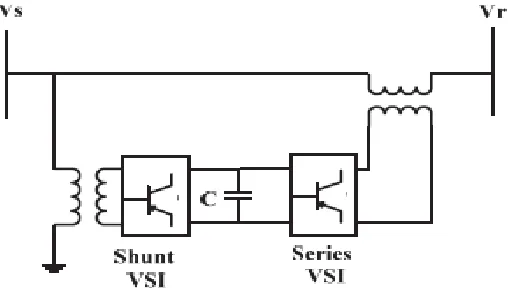
III. UNIFIED POWER FLOW CONTROLLER
UPFC are being used extensively in power systems among Flexible ac transmission systems (FACTS) based power electronic converters because of their ability to provide flexible power flow control. A schematic of the UPFC [2] is shown in Fig. 2. It consists of two voltage source inverter (VSI). One is a shunt VSI and the other is series VSI. The shunt and series VSI are connected via a DC link, which includes a DC capacitor (C). The shunt converter of UPFC controls the connected UPFC bus and DC link capacitor voltage. The series converter of UPFC controls the line active and reactive power flow by injecting a series voltage of adjustable magnitude and phase angle. Under steady state condition, series converter provides the main function of UPFC [5] by injecting a voltage the UPFC is the only device which can fulfill all these functions and thereby meet multiple control objectives by adding the injected voltage Vpq, with appropriate amplitude and phase angle, to the terminal voltage V0(Using
phasor representation, the basic UPFC power flow control functions.
Fig.3. A phasor diagram illustrating UPFC operation
VSrepresents sending end voltage, Vrreceiving end voltage, Vpqis UPFC voltage, which is inserted in the power system through the series transformer, X is transmission line reactance and Iis the line current. The UPFC Series side and shunt active and reactive power flow are given by
(1) (2) (3) (4) Where and r are control variables
At UPFC shunt side the active and reactive power flows are given as
(5)
Qi1= -rbsVi
2FRVȖ4
conv1-bsVj2+bsViVj
FRVș
i (6)Whereas series side equations are
(7)
(8)
The UPFC injection model is thereby defined by constant series branch susceptance (bcs) which is included in the
system bus admittance matrix and bus power injections Psi, Qsi, Psj, Qsj. If there is a control objective to be DFKLHYHGWKHEXVSRZHULQMHFWLRQVDUHPRGLILHGWKURXJKFKDQJHRI83)&SDUDPHWHUVUȖDQG4conv1.
IV. MODELING OFINDUCTION GENERATOR
Fig.4. Induction generator model
Induction generator is modelled using MATLAB/SIMULINK with the help of flux equations given below: The equations for flux linkages [7] are:
… (7)
... (8)
… (9)
…. (10) Equations for mutual flux linkages are given below
……… (11)
………. (12)
Thus the machine is modeled in SIMULINK using the above equations and on the load side of induction generator a 3 phase voltage is applied.
V. PWM GENERATOR FOR UPFC
UPFC consist of a voltage source converter. For controlling the gate pulse of IGBTs in the VSC PWM generator with POD controller is used the sinusoidal voltage coming out of POD controller is used to compare with triangular wave. The figure shows the modeling of PWM generator for UPFC. Here the voltage is compared with reference signal and given to POD controller and the signal is compared with triangular wave of 20 KHz to produce the gate pulses for the converters. Thus the gate pulse can be controlled.
VI. PODCONTROLLER
The UPFC controller parameters constitute a POD controller[8]. The POD controller consists of a general gain, a low-pass filter, a washout high pass filter, a lead compensator, and an output limiter. But it seems that there is no effect with lag lead filters and on eliminating the system is reduced with a transfer function which is composed of a transducer with a gain which is followed by a washout filter. The main purpose is to remove unnecessary ripples. The signal obtained at the output is limited. The parameters are K, T1, T2, T3 which is used for the control of pulse. The controller is tuned with the values for the voltage source converter. The values are K= 1.1058PU, T1=0.068Sec,
TW1=0.145Sec, TW2= 0.385Sec.
Fig.6 POD controller
Transfer function constitutes lead-lag filters which can be used for phase compensation of POD controllers. A POD controller is tuned to a value providing necessary damping to stabilize the power system after severe disturbances.
Fig.7. Induction Generator with UPFC
VII. RESULTS ANDDISCUSSIONS
UPFC is a combination of shunt converter and series converter with a common dc link capacitor as a source. During the occurrence of fault power quality problems will dominate and there will be a sudden fall in voltage at the instant between 0.1sec and 0.2sec. Therefore Shunt converter will provide the necessary reactive power need for dc link capacitor whereas series converter will inject a voltage to the system for compensation. At the time of fault voltage has fallen to 1kV but after compensation by UPFC it has raised to 9kV and Total Harmonic Distortion (THD) during fault has improved from 179.17% to 0.76%. By introducing UPFC on the load side of induction generator the stability of induction generator will improve. This assures the FRT capability and improves the power quality.
Fig.8. Voltage vs Time at the instant of fault before compensation.
Fig.9 Voltage vs Time after compensation with UPFC
Fig.10. THD before compensation. Fig.11. THD after compensation with UPFC
Fault is one of the severe problems that Induction generators face while generating power in remote areas. There is a sudden increase in reactive power which will cause sudden voltage sag during fault it will cause problems to the load connected to it. So we use UPFC to compensate by injecting a voltage in to the system with the help of shunt converter and series converter and hence necessary compensation can be obtained. The gate pulse of IGBT is controlled by a PWM generator with POD controller. Thus by POD controller serves a major role in improving power quality by eliminating ripples. Hence the compensation is done with UPFC in SIMULINK platform and the problem is completely eliminated which is clear from output waveform and THD values. Hence by reactive power compensation by UPFC the problem is eliminated which is the main aim of the paper.
REFERENCES
[1] Mehdi Mohammedzadeh Rostami, Soodabeh Soleymani ”Impact of FACTS devices on power quality of Self Excited Asynchronous Generator due to load fluctuations”, IEEE Canadian Conference on CCECE,2012.
[2] M. Rama Sekhara Reddy and M.Vijaya Kumar. "Power Quality Improvement in DFIG based Wind Energy Conversion System using UPFC", IOSR Journal of Engineering (IOSRJEN), vol. 3, no. 1, pp. 46-54, Jan. 2013.
[3] Parvej khan, Himmat singh “Power Flow Control In A Transmission Line Through UPFC”,International Journal of Emerging Technology and Advanced Engineering Website: www.ijetae.com (ISSN 2250-2459, ISO 9001:2008 Certified Journal, Volume 2, Issue 12, December 2012).
[4] 5&'XJDQ0)0F*UDQDJKDQDQG+:%HDW\ʊElectric Power Systems Quality. 2ndEdition McGraw Hill, NewYork, 2006.
[5] Ch.Chengaiah, R.V.S.Satyanarayana “Power flow assesment in transmission lines using simulink model with upfc”, 2012 International Conference on Computing, Electronics and Electrical Technologies [ICCEET].
[6] S.Divya, U.Shyamala, “Power Quality Improvement In Transmission Systems Using DPFC”, IEEE sponsored 2nd international conference on electronics and communication system (ICECS 2015).
[7] Burak Ozpineci, Leon M.Tolbert“ Simulink Implementation of Induction Machine model”, IEEE 2003.