R E S E A R C H
Open Access
Fault diagnosis of induction motors utilizing local
binary pattern-based texture analysis
Md Rifat Shahriar, Tanveer Ahsan and UiPil Chong
*Abstract
Fault diagnosis of induction motors in the practical industrial fields is always a challenging task due to the difficulty that lies in exact identification of fault signatures at various motor operating conditions in the presence of
background noise produced by other mechanical subsystems. Several signal processing approaches have been adopted so far to mitigate the effect of this background noise in the acquired sensor signal so that fault-related features can be extracted effectively. Addressing this issue, this paper proposes a new approach for fault diagnosis of induction motors utilizing two-dimensional texture analysis based on local binary patterns (LBPs). Firstly, time domain vibration signals acquired from the operating motor are converted into two-dimensional gray-scale images. Then, discriminating texture features are extracted from these images employing LBP operator. These local feature descriptors are later utilized by multi-class support vector machine to identify faults of induction motors. The efficient texture analysis capability as well as the gray-scale invariance property of the LBP operators enables the proposed system to achieve impressive diagnostic performance even in the presence of high background noise. Comparative analysis reveals that LBP8,1is the most suitable texture analysis operator for the proposed system due to its perfect classification performance along with the lowest degree of computational complexity.
Keywords:Fault diagnosis, Induction motors, Local binary pattern, Texture analysis, Background noise, Support vector machine
1. Introduction
Induction motors are one of the most widely used ma-chines on which industrial production processes depend on. Faults of these vital equipments can cause massive financial loss to the production plants which motivated the researchers to investigate and develop efficient fault diagnosis systems for this kind of rotary equipments [1,2]. Numerous fault diagnosis methods for induction motors have been proposed so far which can be classi-fied in three main types depending on their diagnosis procedure [1], namely model based, signal based, and data based. However, signal processing is a crucial part for all of these three types but with a different impact and role. The most popular signal processing techniques include time domain analysis, frequency domain techniques like spectral analysis, and time-frequency domain methods such as short-time Fourier transform (STFT) or wavelet analysis. The main purpose of signal processing step in a
fault diagnosis system is to reveal the fault signatures from the measured quantities which is a difficult task in the presence of background noise.
Mechanical vibrations, obtained by the accelerometers mounted on the motor body, are widely used for the detection and diagnosis of induction motor faults. In a practical industrial environment, motors are usually coupled with other mechanical components of different speeds which also contribute to the measured vibration along with the motor of interest. As a result, the mea-sured vibration signal contains unavoidable background noise coming out from other coupled mechanical sub-systems and sometimes from the sensor itself. This un-expected noise component can mask the fault signature within the acquired signal which will make the fault diagnosis difficult. To separate or reduce noise compo-nent from the signal of interest, several noise cancelation methods have been proposed in the literature which in fact utilized adaptive or wavelet-based filtering processes. In [3], Lee and White proposed a two-stage adaptive line enhancer to enhance the measured vibration signal. * Correspondence:[email protected]
Department of Electrical and Computer Engineering, University of Ulsan, Bldg. 7, Room 318, 93 Daehak-ro, Nam-gu, Ulsan 680-749, Republic of Korea
Application of self-adaptive noise cancellation algo-rithm was illustrated in [4] by Antoni and Randall. Again, a denoising algorithm for vibration signals incorp-orating NeighCoeff shrinkage model with dual-tree complex wavelet transform was proposed by Wang et al. in [5]. However, all of these existing noise reduction algorithms work as a preprocessing step of fault signature extraction and increase computational complexity of a fault diagnosis system.
To achieve higher diagnostic performance as well as attain robustness to environmental noise, Do and Chong in [6] proposed a fault diagnosis system using features of vibration signal in two-dimensional domain. In fact, it converted one-dimensional vibration data into two-dimensional gray-scale image and extracted local features utilizing scale invariant feature transform (SIFT). The 128-dimensional keypoint descriptors, produced by SIFT, were utilized for the classification of motor faults. Robustness of this scheme was claimed due to the fact that it converted signals into images, and the added noise acts as illumination variation when transformed into images. As SIFT is invariant to image rotation, translation, and scale variation [7] and partially invariant to illumination changes, so efficient diagnosis of motor faults was expected even in the presence of background noise. However, robustness of this SIFT-based fault diagnosis system was not justified with necessary experimental results; therefore, applicability of this kind of system in a noisy industrial environment remained as a question. Besides, there are some critical drawbacks of applying SIFT, one of which is uncertainty in the number of keypoints for different images and another one is high computational cost for the processing of 128-dimensional feature descriptors. To mitigate complexity of unequal keypoint descriptors, adaptive clustering technique was incorporated for the creation of ‘texton dictionary,’ and later, it was utilized in distance-based pattern matching for identifying a fault instance in [6]. However, limitations caused by the application of SIFT in fault diagnosis system can be avoided by replacing this method by a superior one with illumination invariance capability. Such an option is the local binary pattern analysis technique, introduced by Ojala et al. [8,9], in which the local binary pattern (LBP) operator provides us with a binary code for each pixel of an image calculated by thresholding the local neighbors at the gray level of the pixel of interest. As the definition states, local binary patterns are useful texture measure-ment which are extremely robust against any monotonic transformation of the gray scale and rotation of the image while determination of these patterns require a low degree of computational complexity [9]. Moreover, it facilitates the generation of fixed and relatively small number of feature descriptors which can be utilized for fault classifi-cation. Considering these benefits of local binary pattern
analysis, in this paper, a fault diagnosis system for in-duction motors is proposed where local image features, related to image textures, are determined by the LBP operator. Later on these feature descriptors are utilized by the classifier to diagnose motor faults. In the pro-posed system, multi-class support vector machine (SVM) is employed for solving classification problems. Performance of the proposed system has been evalu-ated for eight different motor operating conditions in a laboratory environment. Moreover, diagnosis capability of the proposed scheme has also been measured in the presence of different noise level to justify its effective-ness in practical industrial application. In addition, a number of LBP variants have been incorporated in the experimental analysis to identify the most suitable texture analysis operator in terms of diagnostic capability and computational complexity.
2. Texture analysis by local binary patterns
The LBP texture analysis operator, introduced by Ojala et al. [8], is defined as a gray-scale invariant texture measure which is derived from a general definition of texture in a local neighborhood. LBP operator labels each pixel of an image by thresholding its P neighbor's intensity values with the center value and converts the result into a pattern code by (1):
LBPP;Rðxc;ycÞ ¼
XP−1
p¼0
s gp−gc
2p; ð1Þ
where s xð Þ ¼ 1x
≥
0 0 x<0;gcdenotes the gray value of the
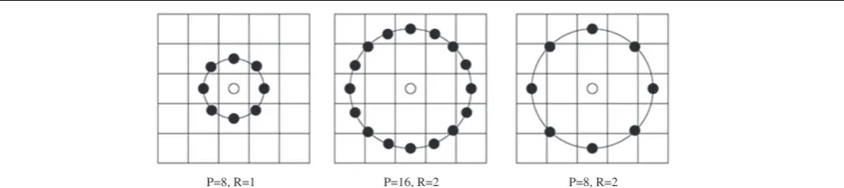
center pixel (xc,yc), andgpcorresponds to the gray values ofPequally spaced pixels on the circumference of a circle with radiusRas shown in Figure 1. The pixel values are se-lected using bilinear interpolation whenever the sampling point is not in the center of a pixel. This individual LBP pattern is capable of describing the texture information at the center pixel.
Being a highly discriminative texture operator, it records the occurrences of various patterns in the neighborhood of each pixel in aP-dimensional histogram. Signed differ-encegp−gcis not affected by changes in mean luminance. Thus, a gray-scale shift does not affect the LBP code of an image. This is achieved due to the consideration of just the signs of the differences instead of their exact values. Therefore, the LBPP,R operator is invariant against any monotonic transformation of the gray scale, i.e., as long as the order of the gray values in the image stays the same, the output of the LBPP,R operator remains constant. Figure 2 illustrates the generation of the basic LBP code for a center pixel withP= 8.
yc∈{0, 1, 2,…,M−1}) is represented by an LBP histo-gram H using (2). The resultant histogram H is the LBP descriptor of that image. Thus, each image is represented by an LBP descriptor which is later used as a feature vector for classification:
Hð Þ ¼τ X M−1
yc¼1 XN−1
xc¼1
f LBPP;Rðxc;ycÞ;τ
; ð2Þ
where τ∈[0,K], f að ;τÞ ¼ 1a¼τ 0 else ;
and K is the
maximal LBP code value. ForP= 8,τwill have 28= 256 different labels; therefore, 256 histogram binsH(τ) will be obtained which can be used as texture descriptors.
Again, for a central pixel gc and its P circularly and evenly spaced neighborsgp,p= [0,P−1], the difference betweengc andgpcan be expressed as a combination of two components dp = gp− gc =sp*mp, where sp = sign (dp) andmp= |dp|. Guo et al. [10] argued thatdpcan be more accurately approximated using the sign component sp than the magnitude component mp. This implies that spwill preserve more information of dp than mp, and hence, it is more likely to result in better pattern recog-nition performance. However, it was also observed that the information contained in the magnitude difference mp can provide a significant performance enhancement [10]. Hence, CLBP_Sand CLBP_M operators were proposed in [10] to encode the sign and magnitude components of local differences respectively (Figure 3).
The CLBP_S operator takes sp to encode the pattern which is essentially the same as the original LBP operator. As the magnitude componentmpis of continuous values
instead of binary ‘1’ and ‘−1’, so it cannot be directly encoded as that ofsp. To ensure consistency with CLBP_S, the CLBP_Moperator is defined as follows:
CLBP−MP;R¼ XP−1
p¼0t mp;c
2p; ð3Þ
wheret xð ;cÞ ¼10 xx≥<cc, andcis a threshold to be deter-mined adaptively [10]. Here, cis taken to be the mean value ofmpover the whole image.
To build a CLBP descriptor, histograms of the CLBP_S and CLBP_M codes are calculated separately and then the two histograms can be concatenated together [10]. This CLBP scheme can be represented as ‘CLBP_S_M’ which is utilized in the proposed fault diagnosis system for the purpose of feature extraction.
Two common extensions for LBP as well as for CLBP are ‘uniform patterns’ and ‘rotation invariant patterns’ [9]. An LBP code is called uniform if the binary pattern contains at most two bitwise transitions from 0 to 1 or vice versa when the bit pattern is traversed circularly. For example, the patterns 00000000 (0 transitions), 01110000 (2 transitions), and 11001111 (2 transitions) are uniform, whereas the patterns 11001001 (4 transitions) and 01010011 (6 transitions) are not. In rotation invariant patterns, each LBP binary code is circularly rotated into its minimum value. Hence, both the patterns 00111100 and 00001111 are mapped to 00001111. The notion of uniform pattern was proposed to take account of and give importance to those patterns which are most com-mon and significant in texture classification. Rotation invariant patterns help to classify rotated texture image by applying rotation invariant mapping.
P=8, R=1 P=16, R=2 P=8, R=2
Figure 1Neighborhood set for differentPandRvalues.
3. Proposed fault diagnosis system
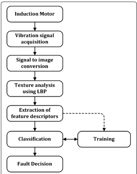
In the proposed fault diagnosis method, vibration signals, acquired from a running induction motor, are first converted to gray-scale images from which discriminating texture features are determined and fault classification is performed. Processing steps of the proposed fault diagnosis system are shown in Figure 4.
3.1. Signal-to-image conversion
The signal-to-image conversion scheme converts a time domain signal into a gray-scale image. The size of the image is dependent on the signal durationt. The choice oftis application specific, and it has to be set such that all possible fault vibrations are accommodated more than once in each of the signal images. Therefore, a large value of t may be desired for higher performance in diagnosis, but an extremely large value oftwould not be practical as it will not only increase the computational burden but also decrease early detection property of the diagnosis method. Considering the abovementioned facts, it is reasonable to set the minimum value of tat tmin= 2 /fmin, wherefminis the lowest possible vibration frequency in hertz. Now, let us consider that the mea-sured vibration signal of tsecond duration contains the L number of samples. The first step of conversion pro-cesses is to normalize the L number of samples so that their values are between 0 and maximum gray-scale pixel intensity. Then, this block ofLnumber of samples is converted into anM×Ngray-scale image where both
MandNare integer numbers andM×N=L. For ensuring optimum utilization of the image pixels in texture analysis, less number of pixels is desired at the image border. Therefore, to keep the summation ofMandNlow, we have to set their values closest to √L. Among the L number of samples, the first N samples construct the first row of gray-scale image; similarly, the nextNsamples construct the second row and so on. This conversion process is illustrated in Figure 5.
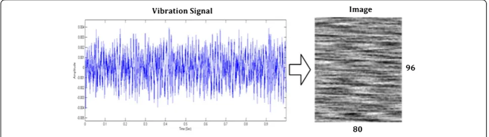
A vibration signal in time domain and corresponding signal image, after conversion, are shown in Figure 6. In this case, the vibration signal contained 7,680 samples, and it is converted into a 96 × 80 gray-scale image. Texture property of this image can be quantified by the LBP operators through appropriate analysis. The texture descriptors, obtained by analysis, are then utilized for fault classification. Thus, signal-to-image conversion scheme facilitates diagnosis of motor faults through classi-fication of the image textures.
3.2. Texture feature extraction
The local binary pattern analysis technique is an ex-tremely powerful gray-scale invariant texture analysis tool which confirms its suitability in the proposed sys-tem. Vibration signal images, obtained from different fault situations, usually exhibit rich texture properties
Figure 4Proposed fault diagnosis system for induction motors.
due to the existence of fault-related frequencies in the vi-bration signals. Again, external noise, induced in the signal from other coupled equipments, appears as gray-scale variation in the converted image. Therefore, powerful tex-ture analysis capability as well as the gray-scale invariance feature of the local binary pattern analysis technique can be exploited in the proposed fault diagnosis systems to achieve optimum diagnostic performance as well as ro-bustness of the system in the noisy industrial environ-ment. To identify the most suitable LBP operator, we analyzed the performance of LBPP,R operator along with its other uniform and rotation invariant variations, namely LBPuP2;R, LBPriP;R, and LBPriuP;R2 [9]. To investigate the contri-bution of magnitude component along with the sign com-ponent in the case of accurate classification, we applied the following CLBP operators, i.e., CLBP _SP,R_MP,R, CLBPSuP2;R MPu2;R, CLBPSri8;1 Mri8;1, and CLBP SPriu;R2 MriuP;R2 for the extraction of texture features in the proposed fault diagnosis system. The objective of this incorpor-ation of different operators is to discover discriminating features which are most efficient for texture analysis in the proposed system. Finally, based on the classification performance and computational complexity consideration, the optimum texture analysis operator is determined for the proposed fault diagnosis system.
3.3. Fault classification
The feature descriptors, obtained by texture analysis, are then utilized by the classifier for the diagnosis of motor faults. Among the classifiers, SVM is suitable for the proposed system as it has the capability of solving learn-ing problem with a smaller number of samples. More-over, SVM supports multi-class classification by adopting the one-against-all (OAA) or one-against-one (OAO) strategy. In the proposed system, classification is performed using linear kernel by exploiting OAA tech-nique. In the case of OAA technique, a binary classifier is trained for each fault instance to discriminate one fault case from all others and outputs the class with the largest outputs. This OAA technique is elaborately explained by Hsu and Lin in [11], whereas its accuracy issue is addressed in [12] by Rifkin and Klautau.
4. Experimental setup and signal database
The experiments were set up under a self-designed test rig (Figure 7) [6] which consisted of motor, pulleys, belt, shaft, and fan with changeable blade pitch angle. In the experiments, six 0.5-kW, 60-Hz, two-pole induction motors were used to produce the vibration data under full-load condition. One motor was operated under normal condition as a benchmark for comparison with
Figure 5Signal-to-image conversion scheme.
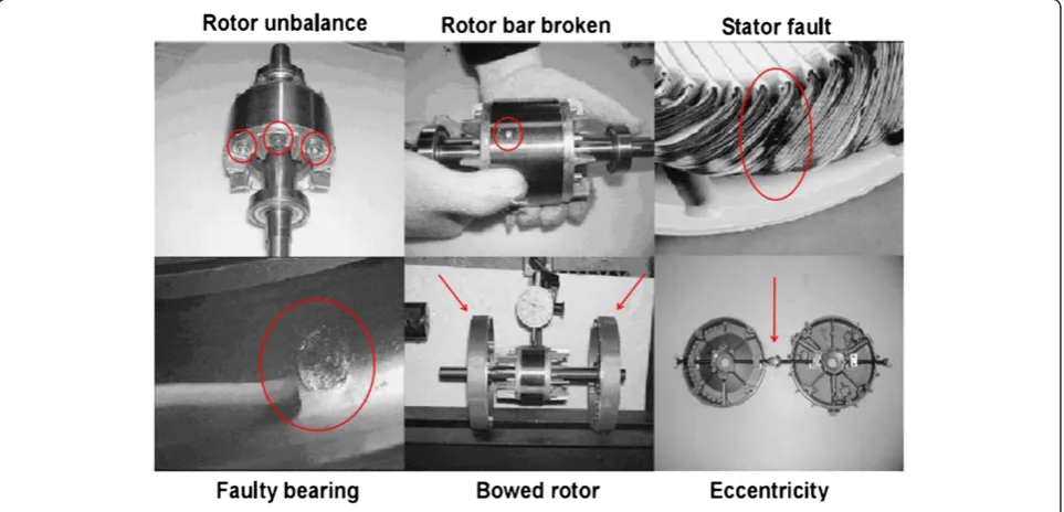
other faulty motors. The other faulty motors were represen-tatives of the following faults: bowed rotor, broken rotor bar, bearing outer race fault, rotor unbalance, adjustable eccentricity (misalignment), and phase unbalance (Figure 8). Thus, eight categories of vibration signals were acquired from the motors, namely angular misalignment (AMIS), bowed rotor shaft (BRS), broken rotor bar (BRB), faulty bearing (outer race) (FBO), rotor unbalance (RUN), normal motor (NOM), parallel misalignment (PMIS), and phase unbalance (PUN). Fault dimensions of the faulty induction motors are described in Table 1. Three accelerometers were attached to the motors to acquire vibration signals
generated in horizontal, vertical, and axial directions. The maximum frequency of interest of the measured signals was 3 kHz which was adequate to include possible mech-anical vibrations [13]. In the experiments, the sampling frequency of the data acquisition unit was 7.68 kHz which was higher than the required Nyquist rate.
As stated above, seven different fault types were studied in our experiments. The minimum possible fault frequency for the mentioned faults was the pole passing frequency which is equal to the slip times the number of poles. For an induction motor, the typical slip is 4% [14]; therefore, we can get a minimum value of signal durationtmin= 0.4167 s. To accommodate tolerance of the slip, a reasonable choice of the signal durationtwas made ast= 1 s. Through the laboratory experiments, we obtained 12 signal samples for every fault category, each of them having 1-s duration and 7,680 number of samples. Each of the vibration signals was converted into a 96 × 80 gray-scale image. As the number of signal category was eight, so we obtained a database containing a total of 96 vibration signal images. As we obtained data from three different sensors, therefore, we had 96 signal images for axial sensor, 96 for vertical sensor, and 96 for horizontal sensor. In Figure 9, vibration signals, acquired from the axial sensor, for the eight signal categories and their corresponding signal images are shown. These signal images are later utilized for the diagnosis of motor faults.
5. Performance analysis and discussion
Four LBP operators, i.e., LBPP,R, LBPuP2;R, LBPriP;R, and LBPriuP;R2, and four CLBP operators, i.e., CLBP_SP,R_MP,R,
Figure 7Experimental setup.
Table 1 Description of induction motor faults
Fault type Fault description Others
BRB Number of broken bar (12 ea) Total number of 34 bars
BRS Maximum bowed shaft deflection (0.075 mm) Air gap (0.25 mm)
FBO A spalling on the outer raceway #6203
RUN Unbalance mass on the rotor (8.4 g)
-Eccentricity (AMIS, PMIS) Parallel and angular misalignments Adjusting the bearing pedestal
PUN Added resistance on one phase 8.4%
CLBP Su2
P;R MuP2;R, CLBPSriP;R MPri;R, and CLBP SPriu;R2 MriuP;R2, were employed for extracting local texture patterns from the signal images. Then, histogram of these patterns was calculated and the histogram bins were con-sidered as feature descriptors. Although texture analysis based on local binary patterns could be performed for different values ofPandR, to ensure minimum computa-tional complexity and lowest number of feature descrip-tors, we kept our analysis limited to P = 8 and R = 1. Feature descriptors, obtained from axial, vertical, and horizontal sensor data, were concatenated to form a com-bined feature vector. The feature vectors were then intro-duced to the multi-class SVM to perform the classification process using OAA method and linear kernel. To measure exact classification performance, cross validation approach was adopted in our experiments. Using a fourfold cross-validation, the input feature vectors were randomly partitioned into four subsets for training data and testing data. Therefore, we had 72 training data and 24 testing data for any iteration. Sequentially, one of the sub-sets was tested using the SVM classifier while trained on the remaining three subsets. Thus, each instance of the whole training set is predicted. The cross-validation accur-acy, obtained in this process, is the percentage of data that are correctly classified.
In this laboratory experiments, a self-designed test rig was used to acquire vibration data which contained pulleys and fan as additional mechanical subsystem coupled to the testing motor. However, in a practical industrial environment, motors may be coupled with many other rotating components which are usually not phase locked to the motor speed. Thus, these subsystems generally provide random contribution to the measured vibration signals which can be reasonably modeled by a Gaussian distribu-tion. Therefore, for proving the robustness of the proposed system to high background noise of an industrial environ-ment, we introduced additive white Gaussian noise to the vibration signals at different signal-to-noise ratio (SNR). Then, the texture features were extracted from those noisy signal images by the abovementioned LBP operators, and classification performance is measured accordingly. In this case, training of the classifier was performed by the feature vectors obtained from the original vibration signals, and the
noisy signals were regarded as test samples. Therefore, 96 training and 96 testing samples were available while evaluating the diagnostic performance in the presence of background noise.
5.1. Identification of optimum LBP operator based on classification performance
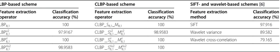
A comparison between overall classification results obtained for LBP, CLBP, and their variants along with SIFT and wavelet-based methods [6] are provided in Table 2.
Besides, Table 3 illustrates the scenario of individual classification accuracy for the different fault categories. According to the obtained results, SIFT and wavelet-based methods are proved to be less accurate than most of the LBP-based techniques as they demonstrate misclassification in different categories including the ‘NOM’ category. Inability to distinguish the normal operation mode from other fault types can drain out the purpose of a fault diagnosis system. Another observation obtained from the classification result is that the so-called uniform patterns, failed to account all the discriminating patterns. This happened due to the fact that texture patterns exhibited by the motor fault signal images were of unusual nature compared to typical images; therefore, many of the discriminating patterns contained more than two spatial transitions (bitwise 0 to 1 change or vice versa). As a result, when the non-uniform patterns were also considered, bet-ter classification results were obtained which is confirmed by the accuracy of LBPri
8;1operator in Table 2. This operator
considers the rotation invariant binary patterns regardless of the uniform definition; therefore, it can discover more discriminating texture features with less number of descrip-tors compared to LBPu8;21 operator. Considering inappropri-ateness, we disregarded LBPu82;1 and CLBPS8u;21 Mu8;21 in our remaining analysis. On the other hand, accuracy obtained by CLBP Sriu8;12 Mriu8;12 operator shows that magnitude com-ponent can add discriminating information, but this state-ment requires appropriate judgstate-ment for different noise levels to quantify its advantage.
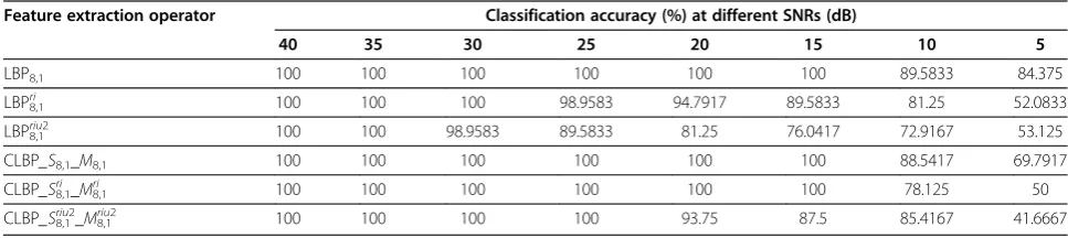
Moreover, noise was introduced at different SNR values in the measured signal, and performance was evaluated to prove robustness of the proposed system
Table 2 Overall classification accuracy for LBP, CLBP, SIFT, and wavelet-based fault diagnosis schemes
LBP-based scheme CLBP-based scheme SIFT- and wavelet-based schemes [6]
Feature extraction operator Classification accuracy (%) Feature extraction operator Classification accuracy (%) Feature extraction method Classification accuracy (%)
LBP8,1 100 CLBP_S8,1_M8,1 100 SIFT 97.916
LBPu2
8;1 97.9167 CLBPSu82;1Mu82;1 98.9583 Wavelet variance 89.582
LBPri
8;1 100 CLBPSri8;1Mri8;1 100 Wavelet cross-correlation 79.165
LBPriu2
against the background noise. A comparative illustration of classification accuracies, achieved by the operators at different noise level, is provided in Table 4. As men-tioned before, the added noise acts as illumination vari-ation when converted to image, whereas the operators we used for feature extraction are gray-scale invariant which enables to achieve higher classification accuracy at reasonably higher noise level. This robustness is extremely useful for a fault diagnosis system to be applicable in a real industrial environment. It should be mentioned here that vibration measured from the motor of interest would be at least three times stronger than the induced background noise [15]; therefore, lower SNR value up to 10 dB would be adequate to simulate practical industrial situation. However, at extremely high noise level (SNR < 10 dB), lower accuracy is observed for some operators because the uneven illumination pro-duced by the inpro-duced noise almost modified the local texture patterns of the entire image. Therefore, texture patterns, obtained from those noisy images, held little correlation with corresponding patterns without noise. From Table 4, it is also evident that at moderate noise level rotation invariant operators ( LBPri
8;1 and LBPriu8;12)
cannot exhibit higher accuracy as rotation invariance
disregards many alternative patterns which would con-tribute for achieving discrimination between the fault types. On the other hand, consideration of magnitude components can increase classification accuracy as far as noise level is not extremely high as observed by the classification accuracy of CLBP Sri
8;1 Mri8;1 and CLBP Sriu8;12
Mriu2
8;1 at noise levels of up to 15-dB SNR. It is caused by
the fact that additional information provided by magni-tude component remained discriminative as long as it is not considerably modified by the noise disturbance and thus boosted the classification accuracy. However, when the noise level is excessively high (SNR = 5 dB), less accurate classification results are observed in the case of CLBP Sri8;1 Mri8;1 and CLBPSriu8;12 Mriu8;12 compared to corre-sponding LBP operators. However, similar observation can be obtained for classification accuracy of CLBP _S8,1_M8,1 as compared to LBP8,1 at SNR values less than 15 dB. Moreover, individual fault classification results at SNR value of 10 dB are provided in Table 5 to identify the most efficient texture analysis operator. From the illustration, it is evident that, although both LBP8,1 and CLBP _S8,1_M8,1 exhibit better performance than other operators in the case of accurate detection of the normal case (‘NOM’), LBP8,1is superior to CLBP_S8,1_M8,1while considering classification
Table 3 Individual classification accuracy for each of the fault categories
Feature extraction method Classification accuracy (%) for different fault categories
AMIS BRB NOM FBO RUN PMIS PUN BRS
LBP8,1 100 100 100 100 100 100 100 100
LBPu2
8;1 100 100 83.33 100 100 100 100 100
LBPri
8;1 100 100 100 100 100 100 100 100
LBPriu8;12 91.67 100 100 100 100 100 100 100
CLBP_S8,1_M8,1 100 100 100 100 100 100 100 100
CLBPSu2
8;1Mu82;1 100 100 91.67 100 100 100 100 100
CLBPSri8;1Mri
8;1 100 100 100 100 100 100 100 100
CLBPSriu8;12Mriu8;12 100 100 100 100 100 100 100 100
SIFT 98.33 98.33 86.67 100 100 100 100 100
Wavelet variance 83.33 100 83.33 100 83.33 83.33 83.33 100
Wavelet cross-correlation 83.33 83.33 83.33 66.67 100 83.33 83.33 50
Table 4 Overall classification accuracy achieved by the operators at different noise levels
Feature extraction operator Classification accuracy (%) at different SNRs (dB)
40 35 30 25 20 15 10 5
LBP8,1 100 100 100 100 100 100 89.5833 84.375
LBP8,1ri 100 100 100 98.9583 94.7917 89.5833 81.25 52.0833
LBP8,1
riu2
100 100 98.9583 89.5833 81.25 76.0417 72.9167 53.125
CLBP_S8,1_M8,1 100 100 100 100 100 100 88.5417 69.7917
CLBP_S8,1ri _M8,1ri 100 100 100 100 100 100 78.125 50
accuracy of the‘RUN’category. Besides, at a higher noise level (SNR = 5 dB), LBP8,1 performed considerably well among these two operators (Table 4). Therefore, we can reach at a conclusion that, as far as classification perform-ance is concerned, LBP8,1 operator should be the best choice for texture feature extraction in the proposed sys-tem. However, in the next section, computational perform-ance of the operators will be evaluated to reach a more rigid conclusion.
5.2. Computational complexity evaluation
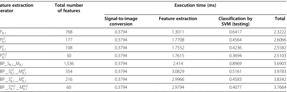
The complexity of calculating LBP code for a gray-scale image is O(n), where n is the number of pixels of the image. However, execution time required for calculating LBP code varies for different operators as mapping operations have to be performed for specific operators to determine rotation invariant and uniform patterns. More-over, classification time also varied depending on the LBP operator used as the number of feature descriptors was dif-ferent. To get a comprehensive measurement of the overall system execution time, calculation time was determined for each of the processing steps of the proposed fault diagnosis system which is presented in Table 6. It should be mentioned here that, in this performance analysis, we used MATLAB implementation of LBP and CLBP operators which were obtained from [16,17] and [18], respectively.
All the measurements were taken in MATLAB 7.10 platform running on a personal computer with Core i7-2600, 3.40-GHz processor and 4 GB of RAM. Along with the classification performance, this computational
measurement would enable us to decide the most suitable feature extraction operator for the proposed system. It is observed that classification time varies for different operators as the number of features varies. The total execution time reveals that feature extraction with LBP8,1operator can provide us with the lowest compu-tational time. It is because of the fact that, like other LBP or CLBP operators, it does not require any mapping or determination of magnitude component.
From the above analysis of classification performance and computational complexity, it is evident that, in the case of fault diagnosis using signal images, each of the available local binary patterns is crucial as it contains some discriminative information. This statement becomes more evident as the noise level in the measured vibration signal is increased. Because at an increased noise level some of the image locations become extremely distorted, there-fore, the texture pattern distribution associated with the image is changed. If all the possible local binary patterns are considered then, reasonably, some patterns will remain undistorted which can provide necessary discriminating information for accurate classification. However, according to the above analysis,LBP8,1operator showed the optimal classification performance even in the case of extreme noise level requiring the lowest computational time.
6. Conclusions
Local texture properties, obtained by local binary pattern analysis, are exploited efficiently in the proposed system for the diagnosis of induction motor faults. The proposed
Table 5 Individual fault classification accuracy of the operators for SNR = 10 dB
Feature extraction operator Classification accuracy (%) for different fault categories
AMIS BRB NOM FBO RUN PMIS PUN BRS
LBP8,1 100 100 91.67 100 25 100 100 100
CLBP_S8,1_M8,1 100 100 91.67 100 16.67 100 100 100
CLBP_S8,1ri _M8,1ri 100 100 0 100 58.33 100 66.67 100
CLBP_S8,1riu2_M8,1riu2 100 100 0 100 91.67 100 91.67 100
Table 6 Computational time evaluation for the proposed system in the case of different texture analysis operators
Feature extraction operator
Total number of features
Execution time (ms)
Signal-to-image conversion
Feature extraction Classification by
SVM (testing)
Total
LBP8,1 768 0.3794 1.3011 0.6417 2.3222
LBPu2
8;1 177 0.3794 1.7708 0.4564 2.6066
LBPri
8;1 108 0.3794 1.7552 0.4236 2.5582
LBPriu2
8;1 30 0.3794 1.7615 0.3694 2.5103
CLBP_S8,1_M8,1 1,536 0.3794 2.414 0.8969 3.6903
CLBPSu2
8;1Mu82;1 354 0.3794 3.0829 0.5161 3.9783
CLBPSri
8;1Mri8;1 216 0.3794 2.9966 0.4583 3.8342
CLBPSriu2
system is tested in the case of eight different motor operat-ing situations in a laboratory setup, and excellent diagnostic performance is obtained. Gray-scale invariance of the LBP operator facilitates the proposed system to exhibit robustness even in higher level of background noise which is justified by the experimental results. Based on classification performance and computational time, LBP8,1operator is identified as the optimum choice for the proposed fault diagnosis system. Future research will be focused on the identification of dominant and most discriminative texture patterns for different motor fault categories and application of the proposed system in the case of multiple motor fault diagnosis.
Competing interests
The authors declare that they have no competing interests.
Acknowledgments
This work was supported by a grant from the University of Ulsan, School of Excellence in Electrical Engineering.
Received: 1 December 2012 Accepted: 5 April 2013 Published: 8 May 2013
References
1. A Bellini, F Filippetti, C Tassoni, G-A Capolino, Advances in diagnostic techniques for induction machines. IEEE Trans. Ind. Electron. 55(12), 4109–4126 (2008)
2. S Nandi, HA Toliyat, X Li, Condition monitoring and fault diagnosis of electrical motors-a review. IEEE Trans. Energy Conversion20(4), 719–729 (2005) 3. SK Lee, PR White, The enhancement of impulsive noise and vibration
signals for fault detection in rotating and reciprocating machinery. J. Sound Vib.217(3), 485–505 (1998)
4. J Antoni, RB Randall, Unsupervised noise cancellation for vibration signals: part I-evaluation of adaptive algorithms. Mech. Syst. Signal Process. 18(1), 89–101 (2004)
5. Y Wang, Z He, Y Zi, Enhancement of signal denoising and multiple fault signatures detecting in rotating machinery using dual-tree complex wavelet transform. Mech. Syst. Signal Process.24(1), 119–137 (2010)
6. VT Do, UP Chong, Signal model-based fault detection and diagnosis for induction motors using features of vibration signal in two-dimension domain. Strojniški vestnik-J. Mech. Eng.57(9), 655–666 (2011)
7. DG Lowe, Distinctive image features from scale-invariant keypoints. Int. J. Comput. Vis.60(2), 91–110 (2004)
8. T Ojala, M Pietikäinen, D Harwood, A comparative study of texture measures with classification based on feature distributions. Pattern Recognit. 29(1), 51–59 (1996)
9. T Ojala, M Pietikäinen, T Mäenpää, Multiresolution gray-scale and rotation invariant texture classification with local binary patterns. IEEE Trans. Pattern Anal. Mach. Intell.24(7), 971–987 (2002)
10. Z Guo, L Zhang, D Zhang, A completed modeling of local binary pattern operator for texture classification. IEEE Trans. Image Process.
19(6), 1657–1663 (2010)
11. C-W Hsu, C-J Lin, A comparison of methods for multiclass support vector machines. IEEE Trans. Neural Netw.13(2), 415–425 (2002)
12. R Rifkin, A Klautau, In defense of one-vs-all classification. J. Mach. Learn. Res. 5, 101–141 (2004)
13. VT Tran, B-S Yang, M-S Oh, ACC Tan, Fault diagnosis of induction motor based on decision trees and adaptive neuro-fuzzy inference. Expert Syst. Appl.36(2), 1840–1849 (2009)
14. L-C Zai, CL DeMarco, TA Lipo, An extended Kalman filter approach to rotor time constant measurement in PWM induction motor drives. IEEE Trans. Ind. Appl.28(1), 96–104 (1992)
15. International Organization for Standardization,ISO 10816–1:1995 Mechanical Vibration—Evaluation of Machine Vibration by Measurements on Non-rotating Parts—Part 1: General Guidelines(ISO, Geneva, 1995)
16. T Ojala, M Pietikäinen, T Mäenpää,[lbp.m], Center for Machine Vision Research
(University of Oulu, 2009). http://www.cse.oulu.fi/CMV/Downloads/ LBPMatlab. Accessed 1 Aug 2012
17. T Ojala, M Pietikäinen, T Mäenpää,[getmapping.m], Center for Machine Vision Research(University of Oulu, 2008). http://www.cse.oulu.fi/CMV/Downloads/ LBPMatlab. Accessed 1 Aug 2012
18. Y Guo, G Zhao, M Pietikäinen,[disCLBP.zip], Center for Machine Vision Research(University of Oulu, 2012). http://www.cse.oulu.fi/CMV/Downloads/ LBPMatlab. Accessed 1 Aug 2012
doi:10.1186/1687-5281-2013-29
Cite this article as:Shahriaret al.:Fault diagnosis of induction motors
utilizing local binary pattern-based texture analysis.EURASIP Journal on
Image and Video Processing20132013:29.
Submit your manuscript to a
journal and benefi t from:
7 Convenient online submission
7 Rigorous peer review
7 Immediate publication on acceptance
7 Open access: articles freely available online
7 High visibility within the fi eld
7 Retaining the copyright to your article