Baghdad Science Journal
Vol.12(3)2015
Single-input Multiple-output Signals Third-order Active-R
Filter for different Circuit Merit Factor (Q)
Adnan A. Qasem*
Shinde G. Narharraa**
*School of Physics, Swami Ramanand Teerth Marathwada (SRTM) University, Nanded, Maharashtra, India
**Principal, Indira Gandhi (SR) College, CIDCO, Nanded, Maharashtra, India *E-mail: [email protected]
Received 2, May, 2014 Accepted 2, September, 2014
This work is licensed under a Creative Commons Attribution-Noncommercial-No Derivatives 4.0 International License
Abstract:
Single-input Multiple-output Signals Third-order Active-R Filter for different Circuit Merit Factor Q Configuration is proposed. This paper discusses a new configuration to realize third-order low pass, band pass and high pass. The presented circuit uses Single-input Multiple-output signals, OP-AMP and passive components. This filter is useful for high frequency operation, monolithic IC implementation and it is easy to design .This circuit gives three filter functions low-pass, high-pass and band-pass. This filter circuit can be used for different merit factor (Q) with high pass band gain. This gives better stop-band attenuation and sharper cut-off at the edge of the pass-band. Thus the response shows wider pass-band. The Ideal value of this filter circuit which is closed to Ideal value of third-order active-R filter is at 0.8≤ Q ≥6. The advantages of this circuit are reduction in size and weight, increased circuit reliability, more economical and easy for manufacturing.
Key words: third-order active-R filter, Single-input Multiple-output signals, circuit
merit factor Q.
Introduction:
The filter is a device designed to separate, pass or suppress a group of signals from a mixture of signals.
These are frequency selective
networks. The operational amplifier (op. amp.) is now accepted as the basic active component for an inductorless filter. The circuit is realized using single pole (as “integrator”) behavior
of an internally compensated
operational amplifier [1, 2, 3-5]. The filter without the capacitor is called an active-R filter and has received much
attention due to its potential
advantages in term of miniaturization, ease of design and high frequency performance [6].It has been also
pointed out in the literature that active-R networks offer substantially low sensitivity characteristics as compared to RC active structures (Soderstand &
Mitra1971).This paper proposes
realization and design method for Single-input Multiple-output Third-order Active-R Filter for different Circuit Merit Factor Q . This filter circuit gives three filter functions low pass, high pass and band pass, with ideal gain roll-off and high pass-band gain. The circuit is designed and studied for different values of circuit merit Factor Q. The filters are extensively used in communication,
entertainment electronics, sonar systems etc.
Proposed Circuit Configuration:
The Propose Single-input
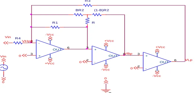
Multiple-output Signals Third-order Active-R Filter for different Circuit Merit Factor Q circuit diagram is shown in figure1. With the advent of the high frequency roll-off in the response of the op-amp, the circuit is
constructed with Single-input
Multiple-output signals; three op-amp (µA741) and four resistances. The
op-amp can be used as an inverting or non-inverting grounded integration depending on connection with identical gain bandwidth product as an active element. This filter gives multiple outputs, which tend three filter functions, low pass, band pass and high
pass. The negative feedback is
introduced through resistances R1; R2
and R3 from the output of three op-amps to inverting input of the first op. amplifiers.
Fig. 1: Proposed Circuit diagram for Single-input Multiple-output Signals third-order active-R filter.
The resistance R2 is tapped at
different points for variation in feedback. The op-amps are coupled such that output of first op- amplifier is connected to non-inverting input of second op-amp and output of second op-amplifier is connected to non-inverting input of third op-amp. Non-inverting terminal of first op-amp, inverting terminal of second and third op-amps are grounded. The input is applied to inverting input of first op- amp through resistance R4.
Circuit Analysis and Design
Equations:
The single-pole model of an op-amp leads to complex gain and the transfer function is given by [7].
0 0/
0
A s A S (1) Where,
A0 = open loop d.c. gain, 0= open
loop (3dB) bandwidth, GB =A00=
gain bandwidth product of
op-amplifier.
0 0/ / ,
A s A SGB S (2) Where, S0
This shows that the op-amp is an
“integrator”, Thus Single-input
Multiple-output Signals Third-order Active-R Filter transfer function at three different terminals are given below. The voltage transfer function for low pass filter.
4 1 2 3
3 2
1 2 3 4
1/ LP
R GB GB GB
T S
X S X S X S X
(3)
The voltage transfer function for band pass filter
Vin
0 -Vcc
R1
0 BR2
0 R4
-Vcc
+Vcc
3
2
6
+
-OUT
+Vcc
3 2
6
+
-OUT
(1-B)R2
3
2
6
+
-OUT
Vin
R
VBp
0
VHp6
VLp
0
+Vcc
R3
0
4 1 2
3 2
1 2 3 4
1/ BP
R GB GB S
T S
X S X S X S X
(4)
The voltage transfer function for high pass filter
4 3
3 2
1 2 3 4
1/
HP
R S
T S
X S X S X S X
(5) Where,
X1= {
( ) }
X2= { ( ) }
X3=
X4={
}
M= ( ( ) ) The circuit was designed using coefficient matching technique with general third-order filter transfer function [4, 5]
3 3 2 2
03 2 2 3
0 1/ 1 0 1/ 1 0
H S H S HS H T S
S S Q S Q
(6)
By comparing (3), (4), and (5) with (6), we get the design equation as
{
( ) }
( )
{ ( ) } =W0 {1+1/Q}
(8)
=W02{1+1/Q} (9) {
}=W0
3
(10) So that Values of R1, R2, R3 and R4 can
be calculated using these equations for different values of Q, f0=15 KHz,
B=0.5 and R=400 Ω (table1).
Sensitivity:
The sensitivities of 0 and Q in this
Wider Pass-band Third-order Active-R Filter are as follows.
= *( ) ( )+
= * +
= * ( ) (
( ) )+
= * +
= * +
= = =
= ( )* ( )(
( ))+
= ( )* +
= ( )* (
( ) ( ( ) )) ( (
)) + = ( )*
+
= ( )* +
= = ( ) = ( )
Thus, passive and active sensitivities are all less than unity. So for all practical purposes this circuit is stable as these sensitivities are very low.
Table1: Resistance values for some
values of Q.
Q R1
(Ω) R2 (Ω)
R3 (Ω)
R4 (Ω)
01 3.4 118 52k 1.4
04 10.8 330 52k 1.1
0.8 16.9 477 52k 1.06
1 19 524.8 52k 1.05
6 32.9 797 52k 1.03
10 34.9 833 52k 1.03
Material and Methods:
The circuit performance was studied with different values of Q
(0.1, 0.4, 0.8, 1, 6 and 10) with constant values of f0=15 KHz, B=0.5
and R=400 Ω for GB=2
. The table 1 shows resistance values of resistors for different Q values. Same circuit was also studied for different values of center frequency f0. The observed
frequency response shows good
response for this active-R filter is from 10 Hz to 1MHz as operating range of this op-amp is 10 Hz to 1.2MHz. Following observations are noticed from experimental study at three different terminals low pass, band pass
and high pass filter function for different values of Q.
Result and Discussion:
A.Low pass response:
10 100 1k 10k 100k 1M
-20 0 20 40 60 80 100 120
Ga
in(d
B)
Frequency
Q=0.1 Q=0.4 Q=0.8 Q=1 Q=6 Q=10
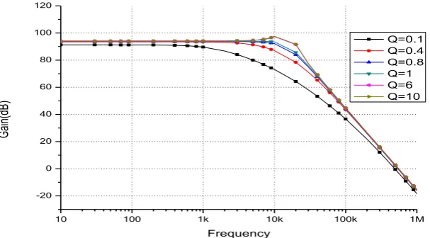
Fig. 2: Low pass (LP) responses for different values of Q
Table: 2. Analysis of Low Pass Response for Graph (Fig 2)
Q
M
a
x
.Pa
ss
-b
a
n
d
Ga
in
(d
B
)
f0L
(k
Hz)
f0
f0L
(
Hz)
%
ch
a
n
g
e
in
f0L Gain Roll-off in stop band Overshoot in the pass band
d
B
/Oct
a
ve
(k
Hz)
Octa
v
e
st
a
rt
in
g
a
t
(k
Hz)
(d
B
)
f0S
L
(k
Hz)
01 91.2 20 5 25 17.8 197 0 0
04 93.5 38 23 60 18 50 0 0
0.8 93.8 43 28 65 18 40 0 0
1 94 43 28 65 18 40 0 0
6 94 44 29 66 18 40 0 0
10 94 44 29 66 18 40 3.3 10
The maximum pass-band gain varies between 91.2dB to 94dB .Also, the gain roll-off per octave varies between 17.8 to 18dB/octave. The maximum pass-band gain increase with increase in values of circuit merit factor Q but after Q≥1 this value gets stabilized at the maximum pass-band
gain 94dB. The Gain roll-off values are closed to ideal value of 18dB/octave
for third order active-R filter.
Overshoot is observed at Q≥10.But in
previous reported configuration
B.Band-pass response:
10 100 1k 10k 100k 1M
-20 -10 0 10 20 30 40 50 60 70 80
Ga
in(d
B)
Frequency
Q=0.1 Q=0.4 Q=0.8 Q=1 Q=6 Q=10
Fig.3: The band pass (BP) response for different Q,
Table: 3. Analysis of Band Pass Response for Graph (Fig. 3)
Q
M
a
x
.
P
a
ss
-b
a
n
d
g
a
in
(d
B
)
f1
(k
Hz)
f2
(k
Hz)
B
W
(k
Hz)
Gain Roll-off / octave in stop band
Leading Part Trailing Part
d
B
/o
ct
a
v
e
Octa
v
e
st
a
rt
in
g
a
t
(
k
Hz)
d
B
/o
ct
a
v
e
Octa
v
e
st
a
rt
in
g
a
t
(k
Hz)
01 39 0.4 56 55.6 6 0.6 12 198
04 52 0.8 60 59.2 6 2 12 60
0.8 56.8 1.1 54 52.9 6 3 12 60
1 58 1.3 50 48.2 6 3 12 60
6 62.4 1.8 45 43.2 6 3 12 60
10 62.4 1.8 45 43.2 6 3 12 60
The maximum pass-band gain varies between 39dB to 62.4dB. Also, the bandwidth varies between 43.2 KHz to 59.2 KHz. The maximum pass-band gain increases with increase in circuit merit factor Q. The bandwidth decreases with increasing in values of circuit merit factor Q but after Q≥1 the bandwidth gets stabilized at 43.2 KHz. For lower values of circuit merit factor Q, this filter can be used for wide bandwidth and for higher values of
circuit merit factor Q it can be used for narrow bandwidth. There is no shift in the central frequency. It is also
observed that the pass band
C.High pass response:
100 1k 10k 100k 1M
-120 -100 -80 -60 -40 -20 0 20
Ga
in(d
B)
Frequency
Q=0.1 Q=0.4 Q=0.8 Q=1 Q=6 Q=10
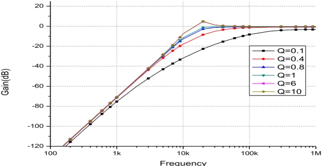
Fig. 4: High pass (HP) responses for different values of Q
Table: 4. Analysis of High Pass Response for Graph (Fig.4)
Q
f0H
(k
Hz)
f0
f0H
(k
Hz)
%
c
h
a
n
g
e
in
f0H
Gain Roll-off in stop
band Gain Stabilization
Pe
a
k
Ga
in
o
f
o
v
er
sh
o
o
t
(d
B
)
d
B
/Oct
a
v
e
Octa
v
e
st
a
rt
in
g
a
t
(k
Hz
)
(d
B
)
fS
(
k
Hz
)
0.1 155 140 90 17.6 20 -3.6 603 0
0.4 47 32 68 18 5 -0.9 137 0
0.8 20 5 25 18 5 0 55 0
1 18 3 17 18 5 0 55 0
6 13 2 15 18 5 0 55 4.5
10 13 2 15 18 5 0 55 4.6
The Gain roll-off in stop-band varies between 17.6 to 18dB/octave which is close to the ideal value of 18 dB /octave for third order active-R filter .Also, the gain gets stabilized almost at 0 dB for all values of Q ≥ 0.8.Also, the response shows overshoot for all the values of Q ≥ 6. But in previous reported configuration the gain stabilized for Q ≥ 5.Also, overshoot is observed for all the values of Q [8-15]. The analysis for the responses are summarizes in the table 3.
Conclusion:
A realization of voltage-mode transfer function for Single-input Multiple-output Signals Third-order
Active-R Filter for different Circuit Merit Factor Q has been presented. The filter circuit is composed only of
three op. amplifiers and four
resistances. Also this single filter circuit gives Multiple-output functions low pass, band pass and high pass filters. It is suitable for high frequency
operation and monolithic IC
implementation. The low pass and band pass performance of the circuit gives high pass band gain and excellent for lower value of f0. For high pass
filter, circuit shows gain stabilization at 0 dB for Q≥0.8. The Ideal value of this
used for both narrow as well as for wide bandwidth.
References:
[1] Huelsman, L. P. Equal-valued
capacitor active-RC network
realisation of a 3rd order low pass
Butterworth characteristics.
Electron. Lett. 1971, 7: 291–293. [2] Mohan, N. Patil, R. L. Ripple pass
function and their active-R
realization. Indian J. Pure Appl. Phys., 1989, 30: 749–750.
[3] Shinde, G. N.; Patil, P. B. Study of active-R second-order filter using
feedback at non-inverting
terminals. Bull. Pure Appl. Sci. 2002,D21: 23–31.
[4] Senani, R.; Gupta, S. S. 2006. Low universal filter using only Current followers as active elements, International Journal of electronics and Communication, 60:251-256. [5] Sun, Zhi-Xiao, Active-R filter: a
new biquadratic with four
terminals. Int. J. Electron. 1983, 54, 523–530.
[6] Hioashimura, M. Active -R realization of current mode high pass filter. Int. J. Electron. 1992, 73: 1279–1283.
[7] Srinivasan, S. Synthesis of transfer
function using the peration
amplifier pole. Int. J. Electron. 1992 73: 1279–1283.
[8] U.N. Chavan and G. N. Shinde, 2013. Synthesis of third order active-R multifunction filter using feed forward input signal, IJMER, 3(6).
[9] Shinde, G. N. Mirkuteand P. R.; Achole, P. D. A third order active R Filter with feedforward input
signal for different center
frequency f0, 2002. Bulletinofpure & AppliedSciences, 21D (2): 77-83.
[10] Shinde, G. N.; Mirkute, P. R. Achole, P. D. 2003. Second order
active-R filter with multiple
feedback for different Q. Indian J. Phys., B77.
[11] Soderstand, M. A. 1976. Design of active-R Filter using only
Resistance and Operational
Amplifier, Int. J. Of Electronics, 40 (5):417-432.
[12] Shinde, G. N. and Achole, P. D. A third order active R Filter with multiple feedback, feedforward input signal and varying positive feedback resistor R. Bulletin of
pure & Applied Sciences,
2005,24D(2): 83-89.
[13] Jinguang Jiang and Yaonan Wang,
2006. Design of atunable
frequency CMOS fully differential fourth order Chebyshev filter, Microelectronics Journal, 37:84-90.
[14] Soderstand M A, Mitra S K, Sensitivity analysis of third- order filter. Int. Journal of Electronics 1971, 30: 265–273.
[15] Shinde, G. N.; and Achole, P. D. 2003. Second order active R Filter
with multiple feedback for
مواقمنا حشرم
ثا
لاعفنا
ثار
لوخذنا تيداحأ ةراشلإا
ا ةدذعتم و
ن
خ
جور
هجرذنا هم
تثناثنا
تفهتخمناةدوجنا مماوع هم ذيذعن
(
Q
)
* مساق اللهذبع ناوذع
**وراه راو ارذواش شيواغ يذىيش
ءاٌضٍفنا تٍهك*
-اداىراساي دشٍح اذَاَاياس ًياىس تعياج
-اشخشاساهاي ذٌذَاَ
-ذُهنا
** ا تٍهك ،ًسٍئشن يذَاغ اشٌذَا
-ذُهنا اشخشاساهاي ذٌذَاَ
:تصلاخنا
قسىنا ِزه ًف ىح ذقن ت
ثار تٍَوشخكنإ ةشئاد ىًٍصح تًٍهعنا لىخذنا تٌداحأ ةساشلإا
ا ةدذعخي و ن
خ سوش
ثاددشخنا شٌشًح ىه حششًنا ازه مًع(ضفخُي شٌشًح حششي ًهو جقىنا سفَ ًف فئاظ و دلار اٍُطعح ذٍحب بجحو تٍناعنا ثاددشخنا شٌشًح ىه حششًنا ازه مًع(ًناع شٌشًح حششي ،)تٍناعنا ثاددشخنا بجحو تضفخًُنا مًع(ثاددشخنا ٍي تيضح شٌشًح حششيو )تضفخًُنا ثاددشخنا شًح ىه حششًنا ازه
ا ثاددشخنا شٌ ٍٍب عقح ًخن
ٌٍددشخنا f1,f2
ٍي ىهعأ ٌىكح ًخنا ثاددشخنا بجحو f2
ٍي مقأ و f1
عبسا ٍي ةشئاذنا ِزه ٌىكخح ذٍح.)
( ثايواقي R1,R2,R3 and R4
تيواقًنا حششًنا ةشئاذب ةشئاذنا ِزه جًٍس ذٍح. ثاشبكي ترلار ٍي كنزكو ) و
.ةشئاذنا ِزه ىًٍصح ًف طقف ثايواقي واذخخسا ببسب ٌا
تٍناعنا ثاددشخهن تبسُناب ذٍفي حششًنا ازه ًف كنزكو
تٌداصخقا شزكأو تٍَوشخكنلإا ةشئاذنا ٌصوو ىجح ًف ضٍفخح ًه ةشئاذنا ِزه اٌاضي ٍيو .تهياكخًنا شئاوذنا ىًٍصح ع واذخخسأب ةشئاذنا ِزه تساسد ىح ذقن . عٍُصخنا تههسو ةدىجنا ميا
( Q شٌشًح لاجي ًف اذج ِذٍفي ةشئاذنا ِزهو . )
تٍنازًنا تًٍقنا ىنا اذج تبٌشق ٌىكح داكح ةشئاذنا ِزه ٍي ِاطعًنا ىٍقنا ٌا ذجو ذٍح تعساىنا ثاددشخنا تيضح ( ةدىجنا مياع تًٍق ٌىكح ايذُع تزنازنا تجسذنا ٍي حششًنا ةشئاذن Q
ٍٍب ) 0.8≤ Q ≥6 .
:تيحاتفمنا ثامهكنا
حششي تزنازنا تجسذنا ٍي لاعفنا ثايواقًنا ,
لىخذنا تٌداحأ ةساشلإا ا ةدذعخي و
ن خ سوش , مياع