Comparative Analysis of Path-finding Algorithm
on Unrestricted Virtual Object Movable
for Augmented Reality
Aninditya Anggari Nuryono, Alfian Ma’arif, Iswanto
Abstract — Pathfinding is a necessary method in gaming, especially in 3D games. Path-finding is used by an object to find paths from one place to another based on the state of the map and other objects. Path-finding requires algorithms that can process quickly and produce the shortest path to reach a destination location. In this paper, path-finding is applied in Augmented Reality. The Intel RealSense camera is used to reconstruct the real environment and display virtual objects. The path-finding algorithm is reviewed that the A*, A* smooth, and Navigation Mesh algorithms. Each of these algorithms is implemented into the Unity 3D object game. Each object game will move simultaneously to the destination point with different starting positions and goals by avoiding many obstacles. It is obtained in the 3D simulation that the A* smooth algorithm is superior to the A* algorithm and NavMesh. The travel time required a game object with A* smooth algorithm is 1.54 seconds faster, and 1.4 seconds compared to A* and NavMesh. Virtual objects can use pathfinding algorithms as a navigation path in the real world. The navigation path is located in the grid area that generated by Intel RealSense cameras.
Index Terms — A*, Unity 3D, Intel RealSense, Pathfinding, NavMesh, Augmented Reality, Intel RealSense
—————————— ◆ ——————————
1.
INTRODUCTION
Augmented Reality (AR) is research in computer science that combines digital and real-world data. AR uses techniques in computer vision, image processing, and computer graphics to merge digital content into the real world [1][2]. Users can see 3D (3D) objects projected by the camera against the real world [3]. Utilization of cameras such as a webcam or 3D camera that has depth can be used in AR technology. One of the depth technology in the 3D camera is Intel RealSense R200 [4]. AR allows real-time interaction between users, native objects, and virtual objects. One example of an AR application can be applied to a navigation system. This navigation system uses the pathfinding method. Pathfinding is a method searching in artificial intelligent (AI) [5][6].
The pathfinding method, such as APF (Artificial Potential Field) [7] and A* (A-Star) algorithm is to find the shortest path from the starting point to the destination point [8][9]. One of the problems with AR is syncing virtual data with the environment. An approach using both marker and markerless methods can solve problems using visual markers, such as barcodes, two-dimensional drawing paper (2D). In the marker method, the virtual object will appear above the marker. This is still one of the problems that exist in AR.
The problem is because the virtual object that appears above the marker cannot move freely because it is limited to the area of the marker.
Therefore, this paper a method will be proposed without using markers to display AR using Intel RealSense 3D cameras. The Intel RealSense R200 camera is used to reconstruct real-world environments in three dimensions. This environment used virtual objects as terrain to appear in the real world. Virtual objects are non-player characters (NPCs) using A*, A* smooth, and NavMesh algorithms as navigation systems
2.
LITERATURE
REVIEW
Game is a form of entertainment that can be played using electronic media [10]. The game required AI so that the game can be more lively and exciting [5]. One of the in-game AI components that can be applied in AR is pathfinding. Some research on Augmented Reality and Pathfinding has been widely practiced. In a study conducted by Kim, et al utilizing AR with a markerless method. This method uses a smartphone camera to display AR object games on pictorial imagery. AR object game designed using the Unity 3D game engine [11]. In a study conducted by Kaydin, et al. Presented an adaptive grid path planning technique, an image-based approach to generating navigation mesh (NavMesh). NavMesh is reconstructed based on images taken from above on an urban 3D model. Navigation simulations in the crowd are done in a virtual environment. Comparison between the adaptive grid method and other path planning algorithms, namely Dijkstra and A* is done to obtain accuracy and better memory. In static path planning, the adaptive grid method shows better performance. Adaptive grid can be applied to both static and dynamic planning [12].
————————————————
• Aninditya Anggari Nuryono received his M.Eng from Department of Electrical Engineering and Information Technology Universitas Gadjah Mada, Indonesia. E-mail: [email protected]
• Alfian Maarif is a lecturer at Department of Electrical Engineering, Universitas Ahmad Dahlan, Indonesia. E-mail: [email protected]
• Iswanto is a lecturer at Department of Electrical Engineering, Universitas Muhammadiyah Yogyakarta, Indonesia.
IJSTR©2020 Subsequent research conducted by Stamford et al combined the A* algorithm and occupancy grids for unexplored pathfinding. This pathfinding navigation is simulated using Unity 3D. The incorporation of the algorithm is applied to Non-Playable Character (NPC) to make environmental representations by themselves and to plan pathways based on this information [13]. Furthermore, research conducted by Kallman et al reviewed the structure and algorithm of navigation to obtain dynamic navigation in real-time with simulations of many agents and in the virtual world. This research uses existing methods such as A*, Euclidean, R-funnel, and Dijkstra algorithms. These methods can be applied to simulations with a busy environment when there are many agents and complex environments in the virtual world [14].
Research is conducted by Algfoor, et al on the study of pathfinding techniques for robotics and video games in the last 10 years. This research categorizes pathfinding algorithms based on the search for 2D and 3D environments. The algorithms are described in this study, such as A* and IDA*, improved A*, IEA* and IDA*, and D * techniques. The video games industry can use this pathfinding algorithm in future generations, which will be based on Augmented Reality interactive as expectations of future trends [15].
AR technology consists of a combination of real-world and computer graphics, the interaction with objects in real-time, the detection of objects or Images, and provides contextual data and information [16]. Augmented Reality uses marker and markerless methods. This method is the method used in AR technology to perform the process of tracking objects that exist in the real world and display virtual objects.
2.1 Marker Based Tracking
Marker-based tracking is illustrated with paper that has a black and white square with a thick black border and a white background. The computer will recognize the position and marker orientation and create a 3D virtual world [17].
2.2 Marker Based Tracking
Markerless based tracking does not require a marker to display digital content [18]. As AR has now been developed by the largest companies, such as Microsoft with Hololens, Google Inc. with Project Tango and ARCore technology, Apple Inc. with ARKit technology, and Intel Inc. with Intel RealSense cameras. Hololens combines virtual reality and Augmented Reality to create a mixed reality. Hololens has a 3D camera for reconstructing a real 3D environment with spatial mapping [19]. Project Tango is AR developed by Google company. Project Tango is designed into a smartphone using a 3D camera. Project Tango has three algorithms to be able to run AR, which is motion tracking, area learning, and depth perception [20]. AR technology using ARCore and ARKit requires only red, reen, and blue (RGB) cameras to visualize virtual objects, while Intel RealSense is a 3D camera developed by Intel company. The perception scene algorithm on Intel RealSense is used to display AR in the real world. In this paper, aka using the Intel RealSense 3D camera. Intel RealSense Camera is shown in Fig. 1.
Fig. 1. Intel RealSense Camera [21]
2.3 Pathfinding
Pathfinding is a much-needed method for many games, especially 3D games. Pathfinding is used to determine the direction of the movement of an object from one place to another based on the state of the map and other objects. In solving pathfinding, algorithms will need to be able to quickly process and produce the shortest direction to reach a destination location. One of the algorithms used for pathfinding is the A* algorithm. Algorithm A* is an improvement of Dijkstra's method by modifying heuristic functions. A* will minimize the total trajectory cost contained in the Dijkstra method.
A* will provide the best solution at the optimal time. In a simple case search path, when there is no obstruction on the map, A* works as fast and as efficient as Dijkstra. In the case of a map with a hitch, A* can find a route solution without being trapped by an existing obstacle [22]. The pseudocode and flowchart of the A* algorithm are shown in Algorithm 1.
OPEN //the set of nodes to be evaluated CLOSED //the set of nodes already evaluated add the start node to OPEN
loop
current = node in OPEN with the lowest f_cost remove current from OPEN
add current to CLOSED
if the current is the target node //path has been found return
for each neighbor of the current node
if the neighbor is not traversable or neighbor is in CLOSED
skip to the next neighbor
if the new path to a neighbor is shorter OR neighbor is not in OPEN
set f_cost of neighbor
set parent of neighbor to current if the neighbor is not in OPEN
add the neighbor to OPEN
2.3 NavMesh
Navigation Mesh (NavMesh) is a data structure that describes the walkable surfaces of the gaming world and makes it possible to find paths from one walkable location to another in the gaming world. Data structures are built, or baked, automatically from existing geometries. NavMesh consists of a convex polygon that covers an empty space, so the path can be found without the occurrence of a collision with a hitch.
This mesh is a pathfinding algorithm integrated with unity 3D and can be used in Augmented Reality applications. In Fig. 2, is shown a convex polygon. The white and gray areas represent areas that are not accessible. Blue areas represent areas that can be accessed and used.
Fig. 2. Convex polygons of NavMesh in Unity 3D
3.
WORKING
SYSTEM
The block diagram of the system in this research starts with system design. The system block diagram of this system in Fig. 3. with an explanation as follow. Start Application is about going to the desired starting position in the user environment and start the app from the Intel RealSense menu. The scan is when the application has started, a text will appear, letting the user place the dot into an area with a certain distance. When you get that distance, there is information to place a point in an area with a less flat surface or more area structure. The start button to perform the scan will appear when the previous conditions are met.
Start application Walk around and scan the environment
Generate grid
Hide mesh Place the virtual
object tin the environment
Fig. 3. Block diagram of the Augmented Reality system
The next is to Generate a grid. This stage starts with a calculation where all the existence of the floor is the area that has been scanned by using the perception scene. The farthest positions of each other are used to generate the grid between these points. This grid is a collection of nodes, with each node on set unwalkable. Next set to walkable if the existing floor position is within the node area. A valid floor node will result in a value depending on how close the floor node is to the unwalkable node. This information is used as a heuristic in pathfinding. The grid will remember the last position of the object to be tracked next.
This will be used with a pathfinding A* algorithm to find the shortest path between AR starting point and AR destination
point. Hide Mesh is a visible mesh that can be set on-off. When scanning the environment, with an excellent environment to see that it has been scanned or not, the condition may result in the system slightly lag when compared to not displaying the mesh. Therefore, to make the system run smoother, the visible mesh is hidden when scans and grid making is done. The last is a Place object virtual. Unity 3D is used to display virtual objects in the real world. 3D environments in the real world are used as AR terrain.
4.
EXPERIMENTAL
AND
RESULT
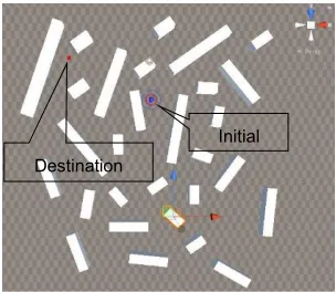
The results of the research stages based on a research methodology that has been done. The results and discussion are starts from the algorithm implementation stage using simulation in Unity 3D and Augmented Reality and simulation data taking in Unity 3D and Augmented Reality. The data used in this study are generated randomly. The data used is the position of the coordinates of virtual objects consisting of x and z coordinates on the simulation of Unity 3D and x, y, and z in the real world. The data used had variations of 29 obstacle coordinate positions, three agents with the same initial position, and one position of the destination point. Each obstacle coordinate position with a simulation test in Unity 3D is shown in Fig. 4.
Fig. 4. Obstacle position in Unity 3D
In the simulation in Unity 3D, the data is analyzed and discussed is the movement of the pathfinding path that is implemented to the game object. Pathfinding simulation in Unity 3D has three scenarios: two scenarios with different coordinate points and one scenario with the starting point to the three objects having the same coordinates. This experiment is conducted five times. This is done to test the consistency of the path through which the object passes. In this study, it has two scenarios, that the target is not moving or in a fixed position coordinate position and the target is moving.
4.1 Scenario 1
IJSTR©2020 coordinates of 0, and on the z-axis with the coordinates of 1.25. The location of the object at the starting point and destination are shown in Fig. 5.
Fig, 5. Initial and Destination position of the object in scenario 1
In Fig. 5, the blue object is the location of the starting point, while the red object is the destination point. The result of object movement to reach the target can be seen in Fig. 6 and Table 1. The black line is the path generated by the movement of the A* algorithm. The green line is the path generated by the A* smooth algorithm, and the blue path is the path generated by the NavMesh algorithm.
Fig. 6. Path of initial to a destination position in scenario 1
TABLE 1.
RUNNING TIME IN SCENARIO 1
Try A* A*
Smooth
NavMesh
1 4.5 seconds 3 seconds 4.4 seconds 2 4.5 seconds 3 seconds 4.4 seconds 3 4.5 seconds 3 seconds 4.4 seconds 4 4.7 seconds 3 seconds 4.4 seconds 5 4.5 seconds 3 seconds 4.4 seconds Mean 4.54 seconds 3 seconds 4.4 seconds
Based on Table 1, the experiment was conducted 5 times, the travel time generated by the object using the A* algorithm was 4.54 seconds. The travel time generated by the object using the A* smooth algorithm is 3 seconds. The travel time generated by the object using the NavMesh algorithm is 4.4 seconds. This shows that the A* smooth algorithm has a higher lead time compared to the A* and NavMesh algorithms.
4.2 Scenario 2
In scenario 2, the initial point coordinates are on the x-axis with the coordinates of -4.33, on the y-axis with the coordinates of 0, and on the z-axis with the coordinates -19.4. The location of the destination is on the x-axis with the coordinates of 4.37, on the y-axis with the coordinates of 0, and on the z-axis with the coordinates of 3.01. The location of points on the coordinates of the starting and destination points are shown in Fig. 7.
Fig. 7. Initial and destination position of the object in scenario 2
The result of object movement to reach the target coordinates are shown in Fig. 8 and Table 2. The black line is the path generated by the movement of the A* algorithm. The green line is the path generated by the A* smooth algorithm, and the blue path is the path generated by the NavMesh algorithm.
Fig. 8. Path of initial to a destination position in scenario 2
TABLE 2.
RUNNING TIME IN SCENARIO 2
Try A* A* Smooth NavMesh
1 8.4 seconds 8.1 seconds 8.8 seconds 2 8.4 seconds 8.1 seconds 8.8 seconds 3 8.4 seconds 8.1 seconds 8.8 seconds 4 8.4 seconds 8.2 seconds 8.8 seconds 5 8.3 seconds 8.2 seconds 8.8 seconds Mean 8.38 seconds 8.14 seconds 8.8 seconds Destination
Initial
Destination
Based on Table 2, the experiment was conducted 5 times, the travel time generated by the object using the A* algorithm was 8.38 seconds. The travel time generated by the object using the A* smooth algorithm is 8.14 seconds. The travel time generated by the object using the NavMesh algorithm is 8.8 seconds. This shows that the A* smooth algorithm has a higher lead time compared to the A* and NavMesh algorithms
4.3 Scenario 3
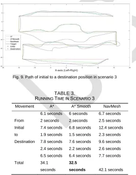
In scenario 3, the target destination object to be achieved in this scenario has coordinates that change as the destination will move. The starting point of the object and destination have the same coordinates. this with the starting point coordinates with the initial point A, the object and target are on the x-axis with the coordinates of 13.09, on the y-axis with the coordinates of 0, and on the z-axis with the coordinates -21,07. The object will follow the target. When the target moves from point A to point B, the object will follow it until the target reaches point H. The visualization of movements in the achievement of a moving target is shown in Fig. 9 and Table 3.
Based on Table 3, the movement of objects following the target movement from point A to H obtained travel time generated by the object using the algorithm A* is 34.1 seconds. The travel time generated by the object using the A* smooth algorithm is 3.25 seconds. The travel time generated by the object using the NavMesh algorithm is 42.1 seconds. This shows that the A* smooth algorithm has a superior travel time compared to the A* and NavMesh algorithms.
Fig. 9. Path of initial to a destination position in scenario 3
TABLE 3.
RUNNING TIME IN SCENARIO 3
Movement A* A* Smooth NavMesh
From Initial to Destination
6.1 seconds 6 seconds 6.7 seconds 2 seconds 2 seconds 2.5 seconds 7.4 seconds 6.8 seconds 12.4 seconds 1.9 seconds 1.5 seconds 2.3 seconds 7.8 seconds 7.6 seconds 9.6 seconds 2.4 seconds 2.2 seconds 2.6 seconds 6.5 seconds 6.4 seconds 7.7 seconds
Total 34.1
seconds
32.5
seconds 42.1seconds
4.3 Running Time
System testing is done on the ability of algorithms to find the path. The travel time data will be compared to find out how fast the A*, A* smooth, and NavMesh algorithms are in finding paths. The smaller the travel time it takes, the faster the object gets to its destination. The travel time of an object depends on the position of the origin and destination coordinates, which affects the length of the path. The farther the coordinates of the starting point and destination, then the travel time gained higher. The closer the coordinates of the starting point and destination, the travel time is getting smaller. The distance and proximity of the starting point and destination affect the length of the path. The data of travel time obtained based on the location of the starting point and destination with the coordinates that have been reviewed in the previous scenario. Based on the experiment conducted 5 times in scenario 1, the travel time generated by the object using the algorithm A* is 4.54 seconds. The travel time generated by the object using the A* smooth algorithm is 3 seconds. The travel time generated by the object using the NavMesh algorithm is 4.4 seconds. This shows that the A* smooth algorithm has a superior travel time compared to the A* and NavMesh algorithms.
In scenario 2, the travel time generated by the object using the A* algorithm is 8.38 seconds. The travel time generated by the object using the A* smooth algorithm is 8.14 seconds. The travel time generated by the object using the NavMesh algorithm is 8.8 seconds. This shows that the A* smooth algorithm has a superior travel time compared to the A* and NavMesh algorithms. In scenario 3, the movement of the object following the target movement from point A to H, the travel time generated by the object using the A* algorithm is 34.1 seconds. The travel time generated by the object using the A* smooth algorithm is 32.5 seconds. The travel time generated by the object using the NavMesh algorithm is 42.1 seconds. This shows that the A* smooth algorithm has a superior travel time compared to the A* and NavMesh algorithms [14].
Based on the three scenarios above, the A* smooth algorithm is superior to the A* and NavMesh algorithms because it has less travel time. This is because the A* smooth algorithm is a modification of the A* algorithm from the ray cast side [13]. The ray cast function in Unity 3D is to provide information to objects that use the ray cast function to find objects in the environment and can return additional information such as the intersection point or not as well as obstacles. Ray cast on the A* algorithm is also used for line-of-sight testing or knowing something that is in front of the object. Pathfinding algorithms A* and A* smooth are implemented into game objects in Unity 3D. Game objects that have been created and have been simulated and implemented into Augmented Reality.
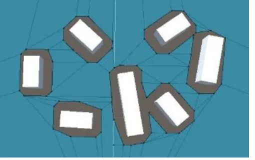
IJSTR©2020 Fig. 10. Path of initial to a destination position in Augmented Reality
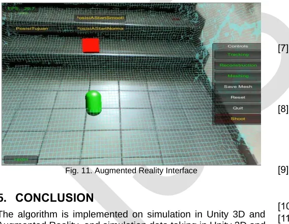
In Fig. 10, is an Augmented Reality movement following the target movement. The target goes up and down the stairs above the grid that overlaid the stairs in the real world. The grid is built using the Intel RealSense 3D camera. In Fig. 11, there are tracking, reconstruction, meshing, save mesh, reset, quit, and shoot menu. Tracking works to track the environment and return tracking results as it did when losing track. "Reconstruction" works to reconstruct the real environment for virtual objects to be used in real life. "Meshing" serves to create three dimensions of the real environment. Save mesh serves to store meshing results. "Reset" function to reset when the scanning results are not after the desired. "Shoot" can issue a virtual object shaped box. "PosisiAStarSmooth" is used to store the coordinates of the movement of virtual objects using the A* smooth algorithm. "PosisiAStar" is used to store the coordinates of the movement of virtual objects using the A* algorithm. "PosisiTujuan" is used to store the coordinates of the movement of the target virtual object.
Fig. 11. Augmented Reality Interface
5.
CONCLUSION
The algorithm is implemented on simulation in Unity 3D and Augmented Reality, and simulation data taking in Unity 3D and Augmented Reality. Pathfinding simulation in Unity 3D has three scenarios, two scenarios with different coordinate points and one scenario with the starting point to the three objects having the same coordinates. This experiment is conducted five times. This is done to test the consistency of the path through which the object passes. In this study, it has two scenarios, that the target is not moving or in a fixed position coordinate position and the target is moving. It is obtained in the 3D simulation that the A* smooth algorithm is superior to the algorithm A* and NavMesh. The travel time required game object with A* smooth
algorithm is 1.54 seconds faster, and 1.4 seconds compared to A* and NavMesh. Virtual objects can use pathfinding algorithms as a navigation path in the real world. The navigation path is located in the grid area that generated by Intel RealSense cameras.
REFERENCES
[1] R. Azuma, Y. Baillot, R. Behringer, S. Feiner, S. Julier, and B. MacIntyre, “Recent advances in augmented reality,” IEEE Computer Graphics and Applications, vol. 21, no. 6, pp. 34–47, 2001.
[2] S. Siltanen, “Theory and applications of marker-based augmented reality,” in Espoo 2012. VTT Science Series 3, VTT, 2012, p. 198 p. + app. 43 p.
[3] M. Billinghurst, A. Clark, and G. Lee, “A Survey of Augmented Reality,” Foundations and Trends® in Human–Computer Interaction, vol. 8, no. 2–3, pp. 73– 272, Aug. 2015.
[4] P. Zanuttigh, G. Marin, C. Dal Mutto, F. Dominio, L. Minto, and G. M. Cortelazzo, Time-of-Flight and Structured Light Depth Cameras. Springer International Publishing, 2016.
[5] P. Norvig and S. J. Russell, Artificial Intelligence: A Modern Approach. Upper Saddle River, NJ: Prentice Hall, 2010.
[6] J. R. Puigvert, T. Krempel, and A. Fuhrmann, “Localization Service Using Sparse Visual Information Based on Recent Augmented Reality Platforms,” in 2018 IEEE International Symposium on Mixed and Augmented Reality Adjunct (ISMAR-Adjunct), 2018, pp. 415–416.
[7] I. Iswanto, A. Ma’arif, O. Wahyunggoro, and A. Imam, “Artificial Potential Field Algorithm Implementation for Quadrotor Path Planning,” International Journal of Advanced Computer Science and Applications, vol. 10, no. 8, pp. 575–585, 2019.
[8] A. Maarif, S. Iskandar, and I. Iswanto, “New Design of Line Maze Solving Robot with Speed Controller and Short Path Finder Algorithm,” International Review of Automatic Control (IREACO), vol. 12, no. 3, p. 154, 2019.
[9] T. H. Cormen, C. E. Leiserson, R. L. Rivest, and C. Stein, Introduction to Algorithms, Third Edition, 3rd ed. The MIT Press, 2009.
[10] P. de Byl, Holistic Game Development with Unity. 2017. [11] S. L. Kim, H. J. Suk, J. H. Kang, J. M. Jung, T. H. Laine, and J. Westlin, “Using Unity 3D to facilitate mobile augmented reality game development,” in 2014 IEEE World Forum on Internet of Things (WF-IoT), 2014, pp. 21–26.
[12] A. Akaydın and U. Güdükbay, “Adaptive grids: an image-based approach to generate navigation meshes,” Optical Engineering, vol. 52, no. 2, p. 027002, 2013.
The application of the A* Algorithm with occupancy grids in Unity3D,” in 2014 14th UK Workshop on Computational Intelligence (UKCI), 2014, pp. 1–6. [14] M. Kallmann and M. Kapadia, “Navigation Meshes and
Real-time Dynamic Planning for Virtual Worlds,” in ACM SIGGRAPH 2014 Courses, 2014, pp. 3:1--3:81. [15] Z. Abd Algfoor, M. S. Sunar, and H. Kolivand, “A
comprehensive study on pathfinding techniques for robotics and video games,” International Journal of Computer Games Technology, vol. 2015, 2015. [16] M. Ramirez, E. Ramos, O. Cruz, J. Hernandez, E.
Perez-Cordoba, and M. Garcia, “Design of interactive museographic exhibits using Augmented reality,” in 23rd International Conference on Electronics, Communications and Computing, CONIELECOMP 2013, 2013, pp. 1–6.
[17] J. Wang et al., “Augmented Reality Navigation With Automatic Marker-Free Image Registration Using 3-D Image Overlay for Dental Surgery,” IEEE Transactions on Biomedical Engineering, vol. 61, no. 4, pp. 1295– 1304, 2014.
[18] S. Bedoya-Rodriguez, C. Gomez-Urbano, A. Uribe-Quevedoy, and C. Quintero, “Augmented reality RPG card-based game,” in 2014 IEEE Games Media Entertainment, 2014, pp. 1–4.
[19] R. Furlan, “The future of augmented reality: Hololens - Microsoft’s AR headset shines despite rough edges [Resources_Tools and Toys],” IEEE Spectrum, vol. 53, no. 6, p. 21, 2016.
[20] T. Araújo et al., “Life Cycle of a SLAM System: Implementation, Evaluation and Port to the Project Tango Device,” in 2016 XVIII Symposium on Virtual and Augmented Reality (SVR), 2016, pp. 10–19.
[21] Intel, “RealSense,” 2015. [Online]. Available: https://www.intel.com/content/www/us/en/architecture-and-technology/realsense-overview.html. [Accessed: 01-Jan-2015].
![Fig. 1. Intel RealSense Camera [21]](https://thumb-us.123doks.com/thumbv2/123dok_us/8621022.1410730/2.612.311.578.377.592/fig-intel-realsense-camera.webp)