Development of “Dropkinson” Bar for Intermediate Strain-rate
Testing
Bo Song1,*, Brett Sanborn1, Jack Heister1, Randy Everett1, Thomas Martinez1, Gary Groves1, Evan Johnson1, Dennis
Kenney1, Marlene Knight1, and Matthew Spletzer1
1Sandia National Laboratories, 1515 Eubank SE, Albuquerque, New Mexico, 87185, USA
Abstract. A new apparatus – “Dropkinson Bar” – has been successfully developed for material property characterization at intermediate strain rates. This Dropkinson bar combines a drop table and a Hopkinson bar. The drop table is used to generate a relatively long and stable low-speed impact to the tensile specimen, whereas the Hopkinson bar principle is applied to measure the load history with accounting for inertia effects in the system. In addition, pulse shaping techniques were applied to the Dropkinson bar to facilitate uniform stress and strain as well as constant strain rate in the specimen. The Dropkinson bar was used to characterize 304L stainless steel and 6061-T6 aluminum at a strain rate of ~600 s-1. The
experimental data obtained from the Dropkinson bar tests were compared with the data obtained from conventional Kolsky tensile bar tests of the same material at similar strain rates. Both sets of experimental results were consistent, showing the newly developed Dropkinson bar apparatus is reliable and repeatable.
1 Introduction
Engineering and biological materials are often subjected to low-speed impact where the amplitude of strain/loading rates lies within the range of intermediate strain rates between 100 and 102 s-1. The material
response at intermediate strain rates is of great interest to automotive industries and electronic packaging [1-3]. However, material properties at intermediate strain rates are rarely characterized due to experimental difficulties, which leaves a significant gap of experimental data between low and high strain rates for high-fidelity strain-rate dependent material model development. In addition, intermediate strain rates have been recognized to play an important role on transitioning in material response and changing in material deformation mechanism from low to high strain rates [4-6]. In addition, both bulk material response and deformation mechanisms have been observed transitioning in the intermediate strain rate regime [4-6]. Therefore, in the past decade, material response at intermediate strain rates has attracted more and more attention.
Current intermediate-strain-rate testing techniques are mainly based on servohydraulic system/drop table or Hopkinson bar methods. Servohydraulic material testing frames are commercially available and relatively easy to operate for intermediate-strain-rate testing [7-10]. However, either servohydraulic system or drop table is based on an open loop system at intermediate strain rates, which challenges the validity of testing conditions. In such servohydraulic-system or drop-table based intermediate strain-rate tests, inertia, or wave propagation, is typically neglected, although it must be
considered when strain rates are i the order of 101 s-1 or
above [11-14]. Ringing in force measurements in servohydraulic test frames becomes more significant at intermediate strain rates due to vibration of the test frame [7-10]. The “ringing” significantly compromises actual material response and must be carefully addressed [7-10, 14-16]. In addition to system inertia, specimen inertia, which is critical to obtain valid material response [8], is not well discussed or properly addressed in current servohydraulic test frames or drop-table-based tests.
In contrast to servohydraulic testing frames or drop-table-based apparatus, Hopkinson-bar based apparatus for intermediate strain rate testing accounts for inertia (or wave propagation) effect in both test apparatus and specimen [17-23]. However, the gas-gun driven Hopkinson bars generate a relatively short duration of loading, usually less than 0.5 ms, which is insufficiently long to deform the specimen to relatively large deformation at intermediate strain rates. In order to generate and accommodate a long loading pulse of loading, the Hopkinson bar system needs to be tens of meters long [17, 21, 23], which is practically impossible in most cases, although a serpentine transmission bar was proposed [18].
and a Hopkinson bar has been proposed for intermediate strain rate testing [24, 25]. Typically, this hybrid method uses servohydraulic test frame or a drop table to generate a relatively long loading pulse to the specimen and applies Hopkinson bar principles to measure the force/stress. However, current hybrid methods have taken care of 1) and 2) above but 3) and 4) have been neglected.
In this research, we developed a similar hybrid apparatus – Dropkinson bar – which combines a drop table and a Hopkinson bar but accounts for all 1) to 4) for material characterization at intermediate strain rates.
2 The Dropkinson bar design
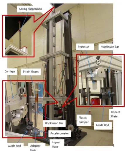
The Dropkinson bar was developed in tension mode. As shown in Figure 1, a long Hopkinson bar was installed parallel to a drop table. The drop table was used to generate an impact by a free drop of a carriage. A cylindrical steel impactor was attached to the bottom of the carriage that strikes the center of an impact plate during a test. The impact plate was made of hardened 4340 steel and had a thickness of 2 inch to minimize the bending wave generated by the impactor. The impact plate was mounted on several guide rods which ensured uniaxial downward travel and also helped attenuate bending effects. Springs were installed on the guide rods between the impact plate and bottom plate to support the gravity of the impact plate. A plastic bumper was installed on the bottom plate that absorbs momentum and restricts the motion of the impact plate during a test. The specimen was attached to the impact plate with an adapter via a hole near the edge of the plate and guide rods. The adapter had ½”-20 female threads on the top and the same size male threads on the bottom. The tensile specimen was threaded into the top part of the adapter. The bottom male adapter thread passed through the hole in the impact plate and was locked with a nut. A small gap was pre-set between the adapter and the impact plate before the experiment. This design allows only tensile force to be applied to the specimen and prevents any possible pre-compression caused by the bending of the impact plate from being transferred to the specimen. The other end of the tensile specimen was threaded into the end of the 1”-diameter Hopkinson bar and secured with a lock nut. A pair of strain gages was attached on the surface of the Hopkinson bar to record the load history transmitted through the tensile specimen. On the top end of the Hopkinson bar, a long spring was installed to suspend the Hopkinson bar to prevent any pre-compression, caused by the gravity of the bar, to the tensile specimen.
Upon the free drop of the carriage, the impactor attached to the bottom of the carriage impacts the impact plate at its center. The impact plate then transfers the impact load to the tensile specimen attached to the edge through an adapter. Such an impact load subjects the specimen to dynamic tension. The tensile stress wave then transmits into the vertical Hopkinson bar through the threads between the specimen and the bar end. The strain gages on the surface of the Hopkinson bar record
the full load history applied to the specimen. The specimen stress is calculated as [26].
( )
E( )
tA A t s 0 0 0 ε
σ = (1)
where A0 and As are cross-sectional areas of the Hopkinson bar and the tensile specimen in gage section, respectively; E0 is Young’s modulus of the Hopkinson bar, ε0 is the bar strain that is recorded with the strain gages. In this apparatus, the Hopkinson bar was made of maraging C300 steel where E0 = 189.7 GPa.
Fig. 1. Photograph of the Dropkinson bar.
Fig. 2. Illustration of specimen displacement measurements. A custom-made laser extensometer was developed and implemented to the Dropkinson bar for specimen deformation measurement. The specimen strain is calculated as [27-29].
where L1 and L2 are displacements of the impact plate and the transmission bar (Fig. 2), respectively, measured with laser extensometer; Ls is the gage length of specimen; c’ is the factor to correct the deformation that occurred outside the gage section.
3 Experimental Verification
In order to verify the newly developed Dropkinson bar apparatus, a conventional Kolsky tension bar and the Dropkinson bar were used to characterize the same materials (304L stainless steel and 6061-T6 aluminum) with identical specimen geometry at the similar strain rates (~600 s-1). The tensile specimen design is shown in
Figure 3. For this specific specimen design, the correction factor (c’) in Equation (2) was determined as c’=0.62, based on the assumption of elasticity-perfectly-plasticity [28, 29].
Fig. 3. Tensile specimen design.
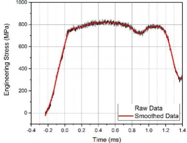
The conventional Kolsky tension bar tests were conducted by following the same procedure presented in Refs. [28, 29]. In the Dropkinson bar tests, copper tubes were selected as pulse shapers and were placed on the impact plate. Figure 4 shows a typical oscilloscope record from a Dropkinson bar test of a 304L stainless steel specimen. The bar strain gage signal was used to calculate the specimen stress with Equation (1), the result of which is shown in Figure 5. As shown in Figure 5, the specimen stress history exhibits a typical elastic-plastic response. A “dip” was observed in the stress history. The dip corresponds to a 12% drop in specimen stress and reflects a slight unloading that was caused by resonant response (bending effect) of the impact plate. After the small dip in stress occurred, the stress drops significantly though the specimen did not fail. This is caused by the tensile wave reflection from the far free end of the transmission bar. The impact plate resonance could be minimized with a better pulse shaping design (or damping design) and/or a reinforced impact plate.
The laser signals on both impact plate and bar end (shown in Figure 4) were used to calculate the specimen strain with Equation (2), the result of which is shown Figure 6. The specimen strain linearly increased with time, which produced a nearly constant strain rate of 530 s-1. This is the result of using the copper tubes to shape
the pulse. However, the specimen strain rate drastically decreased at 0.5 ms, due to the resonant response of the impact plate (Figure 6). From the stress and strain
histories shown in Figures 5 and 6, the engineering stress-strain curve was obtained. In this study, the experimental data up to a strain of 0.27 was used before the resonant response or wave reflection occurred.
Following the same procedure, five experiments were repeated and the average curve from the five experiments was used to represent the tensile stress-strain curve of the material from the Dropkinson bar tests.
Fig. 4. Oscilloscope records from a Dropkinson bar test of 304L stainless steel.
Fig. 5. Stress history in the specimen.
(a)
(b)
Fig. 7. Comparison of Stress-Strain Curves Obtained from the Dropkinson Bar and Conventional Kolsky Tension Bar Tests of a) 304L stainless steel ; and b) 6061-T6 aluminum.
Figure 7 compares the averaged stress-strain curves of 304L stainless steel (Figure 7(a)) and 6061-T6 (Figure 7(b)) obtained from the Dropkinson bar and conventional Kolsky tension bar experiments. The flow stress obtained from the Dropkinson bar tests is approximately 3% higher than that obtained from the conventional Kolsky tension bar tests. However, when accounting for standard deviation during plastic deformation, the stress-strain response obtained from the Dropkinson bar tests is consistent with that obtained from the conventional Kolsky tension bar tests. Therefore, the newly developed Dropkinson bar demonstrates the capability for mechanical characterization of materials at intermediate strain rates with high reliability and repeatability.
4 Conclusion
A new apparatus – “Dropkinson Bar” – has been successfully developed for material property characterization at intermediate strain rates. This Dropkinson bar combines a drop table and a Hopkinson bar. The drop table is used to generate a relatively long and stable low-speed impact to the specimen, whereas the Hopkinson bar principle was applied to measure the
load history to account for inertia effects in the system. In addition, pulse shaping technique was applied to the Dropkinson bar to facilitate uniform stress and strain as well as constant strain rate in the specimen. The Dropkinson bar was used to characterize 304L stainless steel and 6061-T6 aluminum at a strain rate of ~600 s-1.
The experimental data obtained from the Dropkinson bar tests were compared with the data obtained from conventional Kolsky tensile bar tests of the same material at similar strain rates. Both sets of experimental results were consistent, showing the newly developed Dropkinson bar apparatus is reliable and repeatable. Sandia National Laboratories is a multimission laboratory managed and operated by National Technology and Engineering Solutions of Sandia, LLC, a wholly owned subsidiary of Honeywell International, Inc., for the U.S. Department of Energy’s National Nuclear Security Administration under contract DE-NA0003525.
References
1. S.K. Paul, A. Raj, P. Biswas, G. Manikandan, R.K. Verma, Mater. Design, 57 (2014)
2. S.J. Lim, H. Huh, (2017) Int. J. Auto. Technol., 18 (2017)
3. J. Jing, F. Gao, J. Johnson, F.Z. Liang, R.L. Williams, J. Qu, IEEE Trans. Components, Packaging and Manufact. Technol., 1 (2011)
4. Z. Liu, T. Huang, W. Liu, S. Kang, Trans. Nonferr. Metals Soc. China, 26 (2016)
5. H. Zhang, K. Zhang, H. Zhou, Z. Lu, C. Zhao, X. Yang, Mater. Design, 80 (2015)
6. S. Mandal, M. Jayalakshmi, A.K. Bhaduri, V.S. Sarma, Metall. Mater. Trans. A, 45A (2014)
7. R. Othman, P. Guégan, G. Challita, F. Pasco, D. LeBreton, Int. J. Impact Eng., 36 (2009)
8. D. Zhu, B. Mobasher, S.D. Rajan, P. Peralta, J. Eng. Mech., (2011)
9. X. Xiao, Polymer Testing, 27 (2008)
10.H. Huh, J.H. Lim, S.H. Park, Int. J. Auto. Technol., 10 (2009)
11.M.A. Mayers, Dynamic Behavior of Materials, Wiley, Hoboken, NJ (1994)
12.J.D. Campbell, Mater. Sci. Eng., 12 (1973)
13.S. Sahraoui, J.L. Lataillade, Eng. Fract. Mech., 60 (1998)
14.H.E. Gardenier IV., A.N. Palazotto, R.A. Larson, J. Aero. Eng., 25 (2012)
15.S. Sahraoui, J.L. Lataillade, Analysis of Load Oscillations in Instrumented Impact Testing. Engineering Fracture Mechanics, 60:437-446 (1998) 16.D. Zhu, S.D. Rjan, B. Mobasher, A. Peled, Exp.
Mech., 51 (2011)
17.A. Gilat, T.A. Matrka, EPJ Web Conf., 6 (2010) 18.W.R. Whittington, A.L. Oppedal, D.K. Francis, M.F.
19.C.C. Roth, G. Gary, D. Mohr, Exp. Mech., 55 (2015). 20.C. Froustey, M. Lambert, J.L. Charles, J.L.
Lataillade, Exp. Mech., 47(2007)
21.H. Luo, W.L. Cooper, H. Lu, Int. J. Impact Eng., 65 (2014)
22.T.J. Cloete, G. Paul, E.B. Ismail, Phil. Trans. Royal Soc. A., 372 (2017)
23.B. Song, C.J. Syn, C.L. Grupido, W. Chen, W.-Y. Lu, Exp. Mech., 48 (2008)
24.M.M. LeBlanc, D.H. Lassila, Exp. Mech., September/October (1996)
25.J.-C. Petiteau, R. Othman, P. Guégan, H. Le Sourne, E. Verron, Strain, 50 (2014)
26.W. Chen, B. Song, Split Hopkinson (Kolsky) Bar, Design, Testing and Applications, Springer, New York (2011)
27.X. Nie, B. Song, C. Loeffler, J. Dynamic Behavior Mater., 1 (2015)
28.B. Song, P.E. Wakeland, M. Furnish, J. Dynamic Behavior Mater., 1 (2015)