1Universit ´e de Toulouse, ISAE/ICA (EA814), 31055 Toulouse Cedex 4, France 2DCNS Ing ´enierie, 56311 Lorient Cedex, France
Abstract. This work aims at studying experimentally and reproducing numerically the failure mechanisms of a ship structure material when submitted to severe conditions of strain and strain rate. Laboratory tests and airblast experiments were accordingly carried out and a constitutive model has been built describing the salient effects of strain hardening, thermal softening, viscoplasticity and void growth induced damage. Numerical simulations were conducted considering plates subjected to various airblast loading conditions. The numerical results show clearly the influence of the damage and further fracture related model parameters, as well as the limitation of the fluid/structure interaction model used in the present work.
1 Introduction
This work aims at studying experimentally and reproduc-ing numerically the failure mechanisms of a ship structure constitutive material when submitted to airblast loading. Depending on the mass of the explosive and on the distance between the structure and the explosive, one can typically observe the deflection of the plate, the nucleation of macro cracks and the phenomenon of petalling. The vulnerability oriented dimensioning of the warship hull requires ac-curate predictions of the three aforementioned states for airblast loaded structures in order to guarantee that the sailing functions are preserved and that the sensitive areas remain sound.
An important experimental campaign, including labo-ratory thermomechanical tests as well as airblast experi-ments allowed for characterizing the behaviour of a ship structure constitutive material under low to high strain rate conditions. The mechanisms of damage and cracking which occur during the deformation processes until the ul-timate failure were identified from micrographic analyses of partially and totally fractured specimens.
Based on these experimental observations, a multi-surface based elastic-thermo-viscoplastic model involv-ing damage was built, intended to reproduce notably the behaviour transition between dense metal plasticity and microporous metal plasticity, see also [1]. Moreover, the modelling approach adopted here aims at palliating the in-capacity of the usual elliptic, pressure dependent plasticity models, including GTN one (see [2], [3]), to describe void growth related damage under shear in a way preserving the classical meaning of the microporosity related damage.
The performances of the model are evaluated by com-paring experimental and numerical results considering airblast loaded plates.
The airblast experimental results are presented in Sect. 2, the modelling approach is outlined in Sect. 3 and the numerical simulations are shown in Sect. 4.
2 Airblast experiments
The material of the present study is a ferritic-pearlitic mild steel employed as structural material for battleship hull.
Designated as DH36, it is composed of about 87% ferrite and 13% pearlite with a lamellar aspect. The microscopic analysis has revealed a negligible proportion of inclusions. The material can accordingly be considered as exempt from particles.
2.1 Experimental results
To qualify the material under consideration regarding ex-plosion loading, airblast experiments were carried out. The samples were machined in the form of square thin plates. The steel plate was held down by two frames fixed to the underlying structure, see figure 1. The explosive was spherical, hung on a post and braces. The mass of the explosive and the distance between the explosive and the plate are controlled parameters. For further details on the experimental set-up, the reader may refer to [4].
Depending on the mass of the explosive C, and on the distance between the plate and the explosive D, one can typically observe three states resulting from the explosion loading : the deflection of the plate (figure 2(a)), the macrocracks incipience and growth (figure 2(b)), and the phenomenon of petalling (figure 2(c)).
2.2 Fracture analysis
Microscopic observations were carried out on laboratory specimens submitted to various strain magnitudes before failure and on airblast loaded plates, see figure 3. They revealed the presence of two different types of damage: quasi spherical micro-cavities occurring inside the ferritic matrix and micro-cracks developing at the ferrite-pearlite interface, see figure 4. Both types of damage initiate at an advanced stage of the deformation process, i.e. require a certain amount of plastic strain for nucleating. In the sequel, damage will tentatively refer to both cavity growth and micro-cracking and will be described via a single internal variable, namely the volume fraction (porosity f) of both quasi-spherical cavities and crack-like voids.
3 Constitutive relations
In the present approach, based in part on the concepts sug-gested in [5], the elastic-thermo-viscoplastic metal
Fig. 1.Airblast experimental set-up.
a)
b)
c)
Fig. 2.Experimental aspects of the plate after airblast for various loading configurations (DCNS-DGA). a) Deflection (C=C0and D=D0), b) Cracking start (C=2C0and D=D0–2.5 mm), c) Petalling (C=2C0and D=D0–5 mm).
considered here is supposed to be initially dense, i.e. exempt from micro-voids. As soon as the conditions of plastic strain, plastic strain rate, temperature and stress triaxiality are satisfied, the material is assumed to be-come micro porous and its behaviour bebe-comes pressure
Fig. 3. Fractography of the plate after petalling revealing the presence of elongated dimples as the result of opening-shear mode of crack propagation (SEM).
a)
b)
Fig. 4.Types of damage as observed in specimens deformed in tension (SEM). a) Quasi spherical micro-voids at grain bound-aries, b) Micro-cracks at ferrite-pearlite interphase.
The yield stress ¯σy in (1) includes a rate independent contributionσy and a strain rate induced overstress σvp:
¯
σy=σy+σvp (2)
Based on the experimental campaign summarized in Sect. 2.1, the rate independent contribution σy in (2) incorporates the combined effects of strain hardening, via a Vtype law, and thermal softening, via a power law:
σy=R0+h(κ)g(T) ;h(κ)=R∞1−exp (−kκ)β
g(T)=1−
T Tmelt
m
(3) where (R0,R∞,k, β) represent isotropic hardening related
constants and (Tmelt,m) thermal softening related
con-stants. With (3), the rate independent contribution σy in (2) takes thus the form
σy=R0+R∞
1−exp (−kκ)β 1−
T Tmelt
m
(4) The isotropic hardening forceris expressed as follows r=h(κ)g(T)=R∞1−exp (−kκ)β
1− T Tmelt m (5) The tension/compression asymmetry is assumed to be controlled by a thermally activated mechanism involving the mean stress, as it is postulated in [6]. The strain rate induced overstressσvp in (2) is accordingly expressed in
the form
σvp=Y
˙ κexp
Vapm
kBT 1/n
(6) where (Y,n) are viscosity related constants and (Va,kB)
behaviour asymmetry related constants.
Assuming the normality rule, the evolution laws are given by: ˙ εpM
0 =−Λ ∂Φ0 ∂pm =
0
˙ εpD
0 =Λ ∂Φ0 ∂σeq
=2Λσ˜eq
¯ σy ; ˙ κ=ε˙pD0
˙ T =
σeq−r
ρC κ˙ (7)
3.2 Constitutive relations for the damaged material
The behaviour of the micro porous material is described via a G-T-N (GTN) like model, see [2] and [3]. The approach adopted here aims at palli-ating the GTN model incapacity to describe void growth related damage under shear and under low and small neg-ative triaxiality in a way preserving the classical meaning
yield locus is given, according to [1], in the form ΦG=σ˜2eq+2q1fcosh−(3/2)q2( ˜pm+p˜r)
−1+q3f2
=0; p˜m=pm/σy¯ ; p˜r=pr/σy¯
(8) Assuming the kinematic pressurepras vanishing when
the porosity f tends to the unity, the former is given by
pr=bln (q1f) (9)
wherebis a non-negative constant.
For the damaged material, also assumed as being standard in the thermodynamic sense, the evolution laws are given by:
˙ εpM
G =−Λ
∂ΦG
∂pm =
3q1q2fΛ
sinh−32q2( ˜pm+p˜r)
¯ σy
˙ εpD
G =Λ
∂ΦG
∂σeq
=2Λσ˜eq
¯ σy ; ˙
κ= σeqε˙ pD G −pmε˙
pM G
(1−f) ¯σy ˙
T =σeqε˙ pD
G −pm˙εGpM−rκ˙ ρC
˙
f = f˙n+ f˙g
(10)
where ˙fg and ˙fn represents the growing rate of existing
(primary) voids and the nucleating rate of secondary voids, respectively. The expression for the void growth rate is de-duced from the matrix material incompressibility whereas the kinetic law for secondary nucleation is assumed to be well described by a W type distribution function, see [7]:
˙ fn=B
˙ σy ˙
fg=(1−f)T rε˙p=(1−f) ˙εGpM ;
ffng(0)(0)==0f0 (11)
where the quantityBinvolves the hole nucleation function ΦI0and the critical stressσcboth detailed in the following subsection:
B= fsup p σc
Φ I0
p−1
exp−ΦpI 0
(12)
3.3 Complementary damage initiation criterion
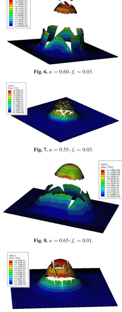
Fig. 5.α=0.65–fr=0.03.
the microporous metal potential have the similar aspect and the corresponding expressions:
ΦI0=σˆ 2+2q
1f0cosh (−(3/2)q2( ˆpm+pˆr))
−1+q3f02
=0; σˆ =σy/σc; pˆm=pm/σc;
ˆ
pr=pr/σc (13)
where σc is a critical stress. To describe the delaying
effects of temperature and strain rate the latter is assumed in the form:
σc=σI+Y
˙
κexp (Vapm/(kBT)) 1/n
; σI=α(R0+R∞) (14)
4 Numerical simulations
The model outlined in Sect. 3 has been implemented as user material in the engineering finite element computation code AR. Numerical simulations of airblast tests were then performed.
The numerical integration is conducted in the G -N rotating frame using the classical return mapping procedure combined with the N-R solving algorithm, see [8] for further details.
The following numerical simulations are systemati-cally conducted using an explicit time integration scheme. The structure is composed of two parts: the steel plate, meshed using 8-node bricks with reduced integration (C3D8R) and containing five elements in the thickness; and two frames, considered as rigid bodies crimping the plate. The explosion induced fluid/structure interaction is numerically simulated via the Ccard of AR– 6.10.
Adiabatic conditions are furthermore assumed to be valid for plastic equivalent strain rate ˙κgreater than 1s−1. In addition, failure is supposed to occur as soon as the porosity reaches the critical value fr, leading numerically
to the erosion of the concerned finite element.
4.1 Parametric study
We are here studying the influence of two parameters, namely the ratio αintervening in (14)2 and the porosity at rupture fr, for a given loading case.
The reference configuration is shown in figure 5. Figures 6 and 7 show configurations with lower values
Fig. 6.α=0.60–fr =0.03.
Fig. 7.α=0.55–fr =0.03.
Fig. 8.α=0.65–fr =0.01.
Fig. 9.α=0.65–fr=0.005.
of the ratio α leading to earlier local damage initiation and consequently earlier structural fragmentation. One can observe the same trend from figures 8 and 9 considering lower values of the porosity at rupture fr.
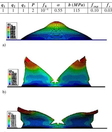
4.2 Comparison with experiment
a)
b)
c)
Fig. 10. Experimental aspects of the plate after airblast for various loading configurations (DCNS-DGA). a) Deflection (C= C0and D=D0), b) Cracking start (C=2C0et D=D0–3 mm), c) Petalling (C=2C0and D=D0–5 mm).
corresponding to those used in the experiments are pre-sented in figure 10.
According to figure 10 one can note a relatively satis-fying (conservative) correlation between experimental and numerical results. Though the initiation of cracking seems to be the most difficult stage to reproduce, the model with a set of constants identified appears capable to describe the petalling of the plate, see Table 1.
It must be noted that the release of burnt gases is not possible when the AR C card, reproducing numerically approximately the fluid/structure interaction, is used. This implies that the explosion induced pressure keeps on being applied on the plate surface all along the loading duration, provoking a petal reversal more impor-tant than in reality. Consequently, for a better description
An important experimental campaign, including laboratory thermomechanical tests as well as airblast experiments allowed for characterizing the behaviour of a ship structure constitutive material. The mechanisms of damage and cracking which occur during the deformation processes until the ultimate failure were identified from micrographic analyses of partially and totally fractured specimens.
Some experimental results were used to build a multi-surface based constitutive model able to describe the tran-sition between dense metal plasticity and microporous metal plasticity. The criterion of damage initiation ac-counts for the accelerating effects of stress triaxiality and for the delaying effects of temperature and strain rate. A modification of the GTN model has also been proposed permitting to describe the cavity growth under shear load-ing.
After identifying a set of material constants from stan-dard experiments, the model was evaluated considering numerical experiments of explosion loaded plates. The corresponding results are encouraging when compared qualitatively with experimental data. A better description of the fluid/structure interaction, numerically reproduced in the present work via the AR Ccard, could allow for improving the predictive capacity of the numeri-cal model.
References
1. P. Long`ere, A.-G. Geffroy, B. Leble, A. Dragon, Int. J. Dam. Mech., DOI: 10.1177/1056789511427472, (2011).
2. A. L. Gurson, J. Eng. Mat. Tech.,99(1977)
3. V. Tvergaard, A. Needleman, Acta metall,32(1984) 4. A.-G. Geffroy, P. Long`ere, B. Leble,, Eng. Fail. Anal.,
18-2 (2011)
5. A. Dragon, Eng. Fract. Mech.,21-4 (1985)
6. S. Graff, S. Forest, S. Strudel, J.-L. Prioul, P. Pilvin, J.-L. Bechade, Mat. Sci. Eng.,A 387-389(2004) 7. A. Molinari, T. W. Wright, J. Mech. Phys. Solids,53
(2005)