327
Milling Microwave Printed Circuit Boards With
Inconsistent Flatness With Safety Function
Quang Pham Minh, Huynh Le Vinh, Phuoc, Minh Hieu Dao, An Nguyen Truong, Tran Phuc Hai, Nam, Louis WY LIU
Abstract: A printed circuit board (PCB) with glitches or inconsistent flatness on the surface plane is common in microwave applications. However, so far there has not been any product capable of overcoming this problem during the PCB fabrication process. In this work, we have successfully constructed a PCB milling machine capable of milling a PCB with uneven flatness. Method: The proposed machine is embedded with a firmware to restructure the g-code in a way that the milling machine is commanded to execute the following procedure: Step 1: Create the Heightmap of the PCB by the probing process; Step 2: Convert probing signal to 2-dimensional grid of surface map; Step 3: During the process of actual milling, alter the height of the milling bit on the fly, according to the surface flatness, and equipped with safety function embedded in laser system. Results: The proposed milling machine has successfully milled soft and non-flat high-speed PCB’s with surface height variations in excess of 150 mm and fabricate an antenna embedded circuit with an ability to pause when the plane angle change drastically. The proposed machine was fully functional and was equipped with all the basic safety functionality, but the total cost spent on this project was around US$ 1500, as opposed to the market price of a similar German-made product being sold at US$70,000. Conclusion: A machine capable of milling microwave PCB’s with an uneven flatness with safety function equipped has been successfully constructed at Vietnamese German University at a cost of US$1800, which is far below the market price of a similar counterpart.
Index Terms: g-code, PCB milling machine, AutoLeveller, LinuxCNC, Mach3, SIW.
—————————— ——————————
1
INTRODUCTION
The drop in price in PCB production in recent years has opened up an opportunity for smaller businesses in Asia, fostering a further demand for high-quality PCB production within a small interval of time. At the moment, the demand for production of high quality PCB’s is highest in the microwave and millimeter-wave industry. PCB’s for microwave or millimeter-wave applications can be three dimensional in structure, with a non-flat surface. In this category of PCB’s, a maximum surface flatness variation up to 3cm is very common. One example is the substrate integrated circuits being used for millimeter-wave applications. In the market, however, not many commercially available PCB milling machines are designed to overcome the substrate flatness problem. In the past, design groups have proposed the use of software known as “AutoLeveller” to overcome this problem. This software basically accepts g-code [3] of the PCB design and modifies the content by insert to the top of the g-code a section responsible for adjusting the drill height for probing. When the modified g-code file is being executed by the firmware embedded inside the machine, this probing section controls the milling machine to measure the entire surface of the PCB and construct surface height gradient map over the entire surface of the PCB. During the process of PCB milling, the milling machine is commanded to adjust the height of the milling bit on the fly at different locations of the PCB. Regardless of the flatness of the PCB’s surface, the resulting PCB is usually avoided of over- or under-milling. However, in order to use “AutoLeveller”, the PCB milling machine executes the probing section. Many commercial PCB milling machines are not designed to handle this user-defined probing section.
On the other hand, “AutoLeveller” works only with LinuxCNC or Mach3. This software does not work with GRBL or any other DIY CNC milling machine. In recent years, there have been several published papers on PCB milling machines [4-8]. To the best of our research, not many of these papers have addressed specifically the issues of a high-speed printed circuit. In this work, a completely new PCB manufacturing system capable of milling a high-speed printed circuit board with uneven flatness has been generated. The proposed PCB manufacturing system is driven by another self-built-in software which is safer and more elegant than “AutoLeveller”. Both the software and the PCB milling machine used for this project were designed and made by students and professors of Vietnamese-German University.
2
METHOD
OF
SOLUTION
2.1 Hardware
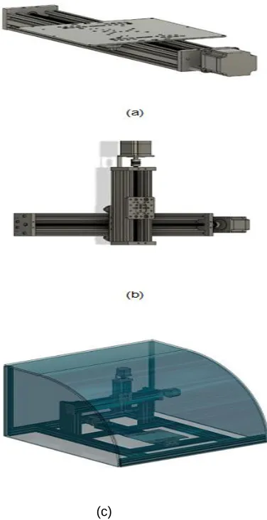
First of all, the hardware was designed with the scanner hardware as demonstrated in Fig. 1a and Fig. 1b to allow the milling bit to move three-dimensionally in the X-, Y-and Z-axis. The mainframe of the system was formed by V-slot aluminum and C-beam. The frame was designed using 8 V-slot profiles and 3 C-beam profiles of aluminum. The frame's bottom consists of two 20x60x800 mm profiles and two 20x60x500 profiles mounting with four L-shaped supports in order to form a rectangular foundation for the frame. Two longer C-beam profiles (length 500 mm) were used as rails for the frame's X-axis and Y-X-axis, and the shorter C-beam profile (length 250 mm) was used as the Z-axis rail. The X-axis C-beam profile is parallel to the bottom of the frame, in addition to the Y-axis and the Z-axis, while the C-beam profile crosses at the top of the frame. The system's movement axes consist of two parts: a) the independent moving Y-axis that is the base axis (Fig. 1a) and b) the X/Z axis mounted together to control the spindle. There were three stepper motors controlling three-dimensional travel. Each of the stepper motors has been attached to a microcontroller driver circuit. The spindle and cutting drill's 3-dimensional motion was guided by the Cartesian manipulator. The Z-frame was mounted on the X-frame in the first place. This allows these two frames to travel along the Y-axis. According to the PCB specification, the spindle mounted on _____________________________________
• Quang Pham Minh, Huynh Le Vinh Phuoc, Minh Hieu Dao, An Nguyen Truong, Tran Phuc Hai Nam are currently pursuing bachelor degree program in electric engineering and information technology in Vietnamese-German University, Vietnam
• Louis WY LIU name is currently senior lecturer in
Vietnamese-German University, Vietnam, PH-+84704624733. E-mail:
328 the Z-frame was allowed to move up and down. All stepper
motors were stepper motors NEMA 23 (size 57) with an angle of 1.8 per step (200 steps/revolution) [2]. Such engines have two stages, each drawing 2.8A and adding a 1.26Nm retaining torque. The spindle has a low run-out defect, high speed (approximately 10,000 to 50,000 RPM). The spindle works at an idle RPM of 20,000 RMPs with an input of 300W. When the working voltage was 100VDC, the torque was 5000G/CM. The spindle RPM can be adjusted by tuning the working voltage through the Speed Governor.
(c)
Fig. 1. a) The rail for the Y-axis; b) The rails for the X/Z axis combined; c) the overall framework of the proposed PCB milling machine.
2.2 The software
The PCB milling machine's firmware as shown in Fig. 2. The Arduino Uno controller machine was the central controller. The motor shield was the CNC v3 with three DRV 4988 motor drivers designed for stepper motor manipulation. The GRBL had to be loaded into the system before installing the firmware. GRBL is a firmware that controls stepper motors and spindles/lasers for Arduino boards. This uses g-code as input and output signals through the pins of Arduino. It takes its input from a computer connected through the USB cable. The Arduino, software converts the g-code into the stepper motor control signals, and outputs these stepper motor control signals through predefined output pins. The signals were then fed to the stepper motors driving the CNC machine axes via stepper motor drivers [4].
Fig. 2. The firmware of the proposed PCB milling machine.
2.3 The Operation of Milling
329 (b)
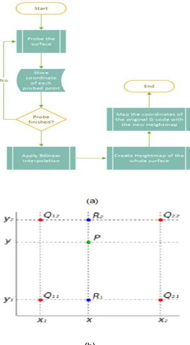
Fig 3. Surface probing function “HeightMap”: a) Flow diagram; and b) sample output where point P is to be determined by bilinear interpolation based on the heights of Q11, Q12, Q22, and Q23.
2.4 The laser re-calibration safety system
Figure 4. Render image of the Laser Safety System.
As an upgraded version of Auto-Bed-Leveling, this system can recalibrate the plane slope and update the status to run g-code. Instead of using initial probing data received from the drill tip, the calculated distance signal from the laser system can interfere and control the miller height at that moment to avoid accidents when the copper plate plane changing its angle. The laser system contains 3 laser distance sensors. These sensors are arranged in an equilateral triangle position
Fig. 5 is such that the center of this triangle aligns horizontally with the drill tip.
Fig. 5. Top-view of Laser Safety System illustrated equilateral triangle positioning.
The height coordinate of the center point of the equilateral triangle is equal to the median of the distances receiving from the laser sensor system described in the following equation:
: desired height to calibrate the drill tip. d1, d2, d3: Distancereceived from laser sensors.
: Debounce distance to the height.
Currently, this system is equipped with a safety mechanism, which automatically halts the miller when the change in height crossed the threshold of 0.1 mm different. However, the software can be upgraded to keep the machine working in a new plane instead of pausing the whole progress.
3 RESULTS
AND
DISCUSSION
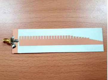
330 Fig. 6. a) Small RF/microwave PCB with coplanar waveguide,
and b) Large and software RF/microwave PCB with a number of coplanar waveguides.
Figure 7. A fabricated endfire antenna [9].
Fig 8. The measured S11 parameters of the endfire antenna as shown in Figure 6 [9]
The current hardware of the machine can be further upgraded to cope with changing printed planes, which means the system can keep printing normal instead of pausing. The current inputs received from laser sensors do not provide enough
constraints to map a new milling position with the previous. The software can only define the plane characteristics when calculating the slope Alpha forming with the previous plane, but each point can slide along the G Axis Fig. 9. To implement this feature, we need to constrain the shape and dimension of the copper board, but this removes the flexibility of the machine, which can run on any board despite its shape and size.
Fig 9. Copper plane after rotating angle Alpha.
4
CONCLUSION
In this paper, we have managed to construct a PCB milling machine capable of milling a non-flat high-frequency PCB with an on-the-go calibration system using a laser distance sensor. The resulting machine was fully equipped with basic functionality. The proposed machine was implemented to capture a g-code and operated as commanded. The keynote of this system focuses on the ability to calculate and halt the miller at any given moment when the machine crosses the height threshold through a laser sensing system. The proposed machine has successfully milled a handful of microwave circuits, including a microwave endfire antenna that has been previously published in [7]. At frequencies from 7.5 GHz and 11 GHz, the measured S11 parameters have swung between -10 dB and -30 dB, which is completely consistent with the previously published results. This machine opens a door for further development. One example is to incorporate of an improved laser system so that the proposed machine can respond rapidly to extreme surface angle changes.
5
ACKNOWLEDGMENT
331
6
REFERENCES
[1] L. L. E. N. America, “LPKF protomat s63 the all-rounder for rapid PCB prototyping,” LPKF, 2017. [Online]. Available: www.lpkfusa.com
[2] C. INC, “Stepper servo motor,” NEMA23-AMT112S,
2018. [Online]. Available:
https://www.cui.com/product/resource/digikeypdf/nem a23-amt112s.pdf
[3] C. Cookbook, “G-code and m-code reference list for milling,” CNCCookbook, 2019. [Online]. Available:
https://www.cnccookbook.com/g-code-m-code-reference-list-cnc-mills/
[4] Kubra Fathima; V. Jean Shilpa; S. H. Mahmood; Machupalli lahari, “Design and Implementation of Three-Axis Cost-Efficient CNC PCB Milling Machine”, 2018 International Conference on Recent Trends in Electrical, Control, and Communication (RTECC), 2008
[5] Rohit Choudhary; Sambhav; Sunny David Titus; P Akshaya; Jose Alex Mathew; N Balaji, “CNC PCB milling and wood engraving machine”, 2017 International Conference On Smart Technologies For Smart Nation (SmartTechCon), 2017
[6] Ariana Tulus Purnomo; Farkhad Ihsan Hariadi; Arif Sasongko, “Development of interface and coordination for control module CNC PCB milling machine”, 2015 International Symposium on Intelligent Signal Processing and Communication Systems (ISPACS), 2015
[7] J. Martheyn Berbesi; K. Saumeth; F. Pinilla, “Parallel control firmware for CNC milling machine based in Arduino”, 2017 12th International Microsystems, Packaging, Assembly and Circuits Technology Conference (IMPACT), 2017
[8] Muhammad Hidayatullah; Farkhad Ihsan Hariadi; Arif Sasongko, “Development of interface and coordination module of FPGA-based controller for CNC PCB milling and drilling machine”, 2017 International Symposium on Electronics and Smart Devices (ISESD), 2017