* To whom all correspondence should be addressed.
Developing Principles and Functioning Algorithms of
the Hardware-software Complex for Electrical Impedance
Tomography of Biological Objects
Grayr Karenovich Aleksanyan1, Nikolay Ivanovich Gorbatenko1,
Artem Igorevich Kucher1, Konstantin Mikhailovich Shirokov
and Chan Nam Phong2
1Platov South-Russian State Polytechnic University (NPI),
132, Prosvescheniya ul., Novocherkassk, 346428, Russian Federation
2Le Quy Don Technical University 236, Hoang Quoc Viet, Ha Noi, Viet Nam
doi: http://dx.doi.org/10.13005/bbra/2251
(Received: 05 July 2015; accepted: 10 August 2015)
This paper discusses the general principles of developing, and algorithms ofoperation of the hardware and software complex for electrical impedance tomography of biological objects, and proposes technical solutions for building the device as a whole, and in separate blocks. It is proposed to use the modular-assembly principle as the basis of the hardware-software complex. The advantages of the proposed approach and the possibilities of its implementation in the ready device are described. The requirements to the electrode belt are defined, and structural diagrams are developed for the measurement board, generator board and the microprocessor unit. The principles of interaction between main units are developed. The archiving unit and record-keeping procedures, display unit, control unit, the unit of communication with a PC are described. Attention is paid to development of the patient’s records. The main algorithms for device operation are defined, and the operation diagram is proposed. The logics of the whole hardware-software complex operation is explained. It is proposed to develop independent program products for measuring reconstruction and data visualization from a biological object. To ensure portability and mobility, a battery pack is provided in the cabinet. It is emphasized that special attention should be paid to the relation between the hardware and software complex and the modern methods and communication protocols for processing tomographic images, such as DICOM.
Keywords: Electrical impedance tomography, biological object, medical imaging, generator board, measurement board, microprocessor unit, algorithm, reconstruction, visualization, block diagram, software, electrodes belt.
The structure of modern non-invasive medical imaging techniques used in clinical practice in recent years includes rapidly developed electrical impedance tomography (EIT)4,5,6 that is a branch
of bioimpedancemetry1,2,3. This method has given
a good account of oneself in breast examination7,
monitoring of lung ventilation8,9,10, and studying
internal features of organs and tissues. The EIT method has several advantages, as compared to the existing technical means of medical imaging, such as the ease of devices hardware implementation, dimensions and weight, the ease of maintenance, and safety for the patient and the medical personnel. At present, there are several commercially available EIT devices11. However,
place, the mathematical apparatus of data processing, low devices resolution and sensitivity, limited 3D imaging possibilities, etc. To solve these problems, many studies are performed worldwide10
to develop new approaches, methods and EIT devices aimed at addressing the comprehensive issues that limit the scope and directions of development.
Methods
This paper, in accordance with the schedule of works and technical specifications of the project supported by the Ministry of Education and Science of the Russian Federation, No.14.574.21.0029, unique project ID -RFMEFI57414X0029, is focused on developing principles of development and algorithms of functioning of the hardware and software complex for electrical impedance tomography of biological objects (HSC EIT BO). Based on the review and analysis of the subject area, studying scientific, technical and regulatory documentation, technical solutions in electrical impedance tomography are proposed, aimed at obtaining new results in this field of research, which need to be solved for the proposed full-scale modeling approach [11]. During the research, the global level of EIT works, and existing technical solutions were estimated. Work is a logical continuation of project No. 14.574.21.0029 (unique project ID RFMEFI57414X0029), and is consistent with earlier undertaken (2014) complex of works in patent research, market research, analysis of algorithms of two-dimensional and three-dimensional medical imaging, and analytical reviewing of the current state of the problem.
RESULTS
The design and operation of HSC EIT BO is based on the modular principle, which is one of the modern and progressive approaches to designing information and measuring systems for various purposes. This is due to the following reasons:
1) During design and development of the HSC EIT BO, an indispensable condition is to use modern electronic devices for collecting and processing information, visualizing reconstructed data, logging the inspection procedure, generating and accounting for
patient charts and records of examinations. 2) Each functional block has to be implemented on a separate printed circuit board. This will ensure functional flexibility of the complex, improve its maintainability, and reduce the cost of consumables and maintenance of the equipment. Some HSC EIT BO units may be autonomous (independent), and the device is designed on a separate printed circuit boards with the possibility of connection with the neighboring units. 3) In case of the necessity to increase
functionality of the HSC EIT BO, to change the conditions of the procedure (or the study), to increase the number of recording channels, and automation of existing units, the use of the block-and-modular principle will greatly simplify and speed up the modernization of the whole HSC without additional structural modifications. 4) The use of the block-and-modular principle
makes it possible to meet aesthetic and ergonomic requirements, as well as to implement the principles of standardization and unification to the HSC EIT BO. 5) The modular principle ensures high
operational reliability,and the ease of maintenance for all HSC EIT BO in general. Figure 1 shows a scheme that explains the principle of building the HSC EIT BO. The scheme has been developed in accordance with the recommendations and results of design described in12.
The composition of these units may be modified depending on the objectives of the study. Structurally, all units are interconnected with each other (or with neighboring blocks) via the addressing and signaling lines. Communication is ensured via standard connectors.
Fig. 1. A scheme that explains the principle of building the HSC EIT BO
BO MB
EB GIU MPU PCCU PC
IU
CU PG
SWrec
SWimag
SWint
PCh UALP
This scheme (Figure 1) uses the following designations: PG - probe current generator board;
BO - biological object; EB - electrodes belt; MB - measurement board; GIU - galvanic isolation unit; MPU - microprocessor unit; PCCU - PC communication unit; IU - indication unit;
PC - personal computer; CU - PC control unit;
SWrec - software for reconstruction of BO’s internal structures; SWimag - software for imaging of BO’s internal structures;
SWint - software for integration with specialized SW of the medical institution; PCh - the unit for generating patients’ charts, reports, surveys;
UALP - the units for archiving and logging procedures, storing numerical examination data and images.
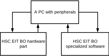
HSC EIT BO hardware part
A PC with peripherals
HSC EIT BO specialized software
Fig. 2. Structural composition of the HSC EIT BO
Electrodes Belt for
electrodes
Adapter for
electrodes Electrode cable MB connector
Electrodes belt
Fig. 3. The principle of EB for HSC EIT BO
surface of the BO. For the ease of experimental studies, the EB should ensure easy replacement of electrodes.
In developing the EB, it is also necessary to use the modular principle. This means that the EB should consist of electrodes, a rubber strap, an adapter for electrodes, the electrode cable, and a standard connector for transmitting signals to the MB connector (Figure 3).
Such a design extends functionality of the EB listed below.
a) The use of the rubber strap ensures reliable contact between patient’s skin and the electrode.
b) The adapter for electrodes makes it possible to use (at the request of the staff) both reusable and disposable electrodes.
the plug electrode cable should match the diameter of the contact hole in the electrodes adapter.
d) The EB should have the possibility (if necessary) to replace the electrodes plug. This is achieved by the use of the “plug-button” adapter.
e) The use of unified standard connectors for connecting the EB with the MB simplifies the process of pairing units and increases the maintainability of the EB.
f) The EB should have a possibility of fast processing electrode surfaces (disinfection, lubrication, etc.).
The design of the EB should provide the possibility of changing the number of electrodes. It is essential for performing the research in the subject area. The simplest and the most reliable method is choosing a rubber strap with holes at a certain distance.
The measurement board MB should be a unit on a separate printed circuit board. The principle of MB for HSC EIT BO is shown in Fig. 4.
Figure 4 uses the following designations:
R - standard multiple contact connector; K - switch;
AMP - amplifier; ADC - analog-to-digital converter.
Fig. 4. The principle of MB for HSC EIT BO
EB
R
?
AMP
ADC
MPU
Measuring board
With regards to the EIT specifics, the capacity of the ADC should be at least 12 bits. The composition of HSC EIT BO should include the PCh unit, as an integral part of modern self-contained medical information and measuring systems. This will lay into the device the principles of logging, archiving and individualization of patients examination results, and will enable automation of the measuring and diagnostics process. In developing the PCh unit, one should be guided by modern legislation of the Russian Federation, the existing regulatory and technical documents, and state standards. Special attention should be paid to personal data protection.
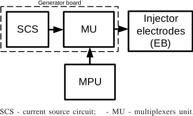
The probing current generator board PG should be made on a separate printed circuit board. The output signal from the PG should be sent to the injecting electrodes via a standard connector. The principle of PG for HSC EIT BO is shown in Figure 5.
The UALP (unit for archiving and logging procedures, storing numerical examination data and
SCS MU
Injector electrodes
(EB)
Generator board
MPU
SCS - current source circuit; - MU - multiplexers unit.
Fig. 5. The principle of PG for HSC EIT BO
images) should be computer-based with the use of SWex, SWimag, SWint.
stopping the procedures of reconstruction and visualization only in the SW of the HSC EIT BO. The IU indication unit is required for alerting and informing the operator (doctor, researcher, etc.) during his work with the HSC EIT BO (procedure, results, etc.). The IU is used for displaying visualized structures of the BO, their analysis and interpretation. The IU should be implemented on the monitor of a PC. The PC monitor is an indispensable element, according to the technical design specifications.
The control unit CU makes it possible to control the procedure of the survey, set operating modes,initiate and stop the HSC SW, save the results of measurement, processing, analysis, reconstruction and imaging both in PC memory and on external media.
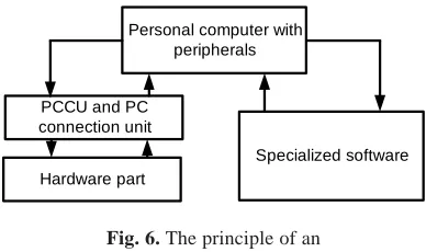
Since the HSC EIT BO is based on a PC with peripherals, the presence of PCCU unit is a necessary condition. The principle of an HSC EIT BO with a PCCU unit is shown in Figure 6.
operated. To do this, the objects of standardization should be defined, and proposals for standardization and unification developed.
The microprocessor unit MPU is a standalone unit with power supply via a serial USB interface. The principle of MPU interaction with other units is shown in Figure 7.
Hardware part
Personal computer with peripherals
Specialized software PCCU and PC
connection unit
Fig. 6. The principle of an HSC EIT BO with a PCCU unit
In accordance with the technical specifications, the PC communication unit should be implemented using a standard USB serial interface.
The unit for archiving and record-keeping procedures, storing numerical data of examination and imaging UALP should be implemented on the basis of a PC with peripherals and an IU. It is also necessary to use the computing capacity and functional capabilities of modern PCs and SW [13]. Archiving and logging means storing the results of patients examination, as and all the information about the place of registration, personnel, images of all 10 of tomographic cross-sections of the BO. There should be a possibility to integrate the developed SW with specialized software of the medical institution, where the HSC EIT BO is
EB
MB PG
MPU PC
Fig. 7. The principle of MPU interaction with other units
It should control the operation of PG and MB via commands from the PC, and ensure consistency of PC, PG and MB operation.
In the design of the HSC EIT BO, it is necessary to use modern electronic base. Organization and control of computing processes should be performed with the use of microprocessor technology. For the development of MPU SW, it is appropriate to use modern development languages and tools that use computing resources of the MPU in an optimal way. Structurally, all units of the HSC EIT BO should be located and secured in a plastic housing, the front panel should have device controls, power devices, EB connectors, and a connector for connection with the PC. The housing should protect the internal parts of the device from dust and moisture, and have a convenient handle for carrying the device. The housing of the HSC should have a battery compartment. This will ensure overall mobility and portability of the HSC EIT.
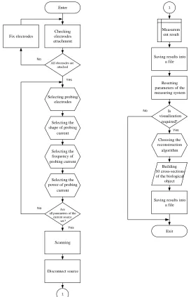
the HSC EIT BO, it is necessary to define the algorithms of each block operation, and the algorithms of units syncing. The sequence of
actions in working with the HSC EIT BO is shown in Figure 8. The user must be able to control the device at any stage of its use.
Fig. 8. Sequence of actions when working with the HSC EIT BO Procedure
start
Measuring
process Reconstruction Visualization Saving results
Stopping the procedure
Yes
Enter
Checking electrodes attachment
No
Yes
1
1
Scanning
Exit
All electrodes are attached
Fix electrodes
Selecting probing electrodes
Selecting the shape of probing
current
Selecting the frequency of probing current
Selecting the power of probing
current
Are all parameters of the
current source set?
No
Disconnect source
Building 10 cross-sections
of the biological object
Yes
Resetting parameters of the measuring system
Is visualization
required?
No
Saving results into a file
Saving results into a file Choosing the reconstruction
algorithm Measurem
ent result
Fig. 9. Block diagram of the HSC EIT BO functioning
Operation of the HSC EIT BO should begin with starting an examination. Next, the user should start the measurement process, followed by the algorithms of reconstruction and
at any moment. In this case, the unsaved data will be lost, and it will be possible to resume the procedure only after starting a new measurement cycle.
In general, the algorithm of the HSC EIT BO operation is shown in Figure 9. It has been developed in accordance with the Terms of Reference for applied research, and with the principles of the HSC EIT BO design11.
High-frequency electric current (1 to 5 mA) is injected into the body by connecting the current source board with high output resistance. During measurement, the output of the current source is connected to one of the measuring electrodes by using a multi-channel multiplexer. The potentials are recorded from the remaining electrodes on the surface of a biological object. Then the current source is connected to the next measuring electrode. This cycle is repeated until all electrodes have been connected. Thus, the current source is serially connected to each measuring electrode, and measurement is performed.
The user sets basic parameters of the current source: current type, current strength, and current frequency. It is possible to use software to select the number of probing electrodes.
A possibility of generating various systems of lead-outs is provided for the research when picking potentials from the BO. For convenience and clarity, the monitor screen should display a map of electrodes location, indicating the injecting and measuring electrodes and electrodes with bad contact with the surface of the biological object. Thus, the user can easily set up his own plan of experiment, describe the measurement report, and test developed algorithms and methods.
The HSC EIT BO uses 10 belts with 16 electrodes in each for picking potentials. According to the technical requirements, there should be a possibility to obtain 10 tomographic slices of the BO with the pitch of 5 mm. The software should assess the time required for image reconstruction. If necessary, the user can save resulting images of the BO slices.
The HSC EIT BO makes it possible to reset user parameters. Thus, the device may be started by re-specifying the measuring and injecting electrodes, and by setting the current source
parameters in the user interface.
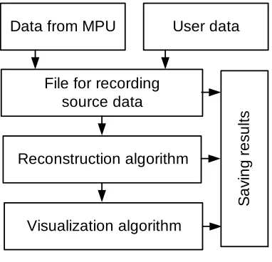
The HSC EIT BO provides the possibility of using the developed software without the hardware. To do so, the user only has to open or manually download the source data file and then run the calculation, reconstruction and visualization algorithms. Figure 10 shows the logic of the HSC with the regard of this possibility.
File for recording source data
Data from MPU User data
Reconstruction algorithm
Visualization algorithm
S
a
vin
g
re
su
lt
s
Fig. 10. The logics of HSC EIT BO with the data from HSC or the data entered by the user
All results, as previously described, are written to the disk storage in the PC. There is a possibility to copy the data from the storage location, and use software to open files for reading and subsequent data processing.
Figure 11 shows the general approach to the HSC EIT BO operation.
the business processes should be formed in accordance with the state standards [14,15].
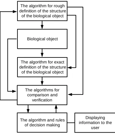
The algorithm of HSC EIT BO operation related to processing the data from the BO may be represented as follows (Figure 12).
etc., and electrical conductivity of the BO is reconstructed and visualized. There is a possibility to use for the research specialized software products [16,17,18] that implement the proposed reconstruction and visualization methods simultaneously with the existing ones. Thus, the tomographic information is defined. It will be later used in the procedure of comparing and verifying the results with the data obtained in the previous stages. With the use of the procedure and certain rules for decision making, an opinion about the results of the study is finally formed with generating the protocols of the examination. Further, all information is displayed to the user in visual form and is stored in non-volatile memory of the device. The HSC software makes it possible to display tomographic images of the BO in several cross-sections at the discretion of the user.
In the design and manufacturing of the HSC EIT BO, one should be guided by modern Russian and foreign normative documents and recommendations related to the devices and systems of medical purpose. Special attention should be paid to the relation of the HSC EIT BO to the modern methods and communication protocols, e.g., to using tomographic images according to the DICOM industry standard (the standard for processing, storing, printing and transmitting information in medical imaging systems)19,20. Special attention should be paid to
the implementation of the user interface, industrial design and ergonomic requirements. In accordance with the technical specifications, the weight of the electronic unit of the developed HSC should not exceed 2 kilograms. Currently, work is underway for designing the user interface of the HSC, and development of a number of algorithms for reconstruction, visualization of electrical
Fig. 11. The general approach to the HSC EIT BO operation
Change (registration)
Reconstruction
Visualization
Saving into a special folder on the PC
Logging
Archiving
Patient's card MPU functioning diagram
Printing out Displaying on the
monitor Saving to external
media
The algorithm for rough definition of the structure
of the biological object
The algorithm for exact definition of the structure
of the biological object Biological object
The algorithms for comparison and
verification
The algorithm and rules of decision making
Displaying information to the
user
Fig. 12. The sequence of HSC EIT BO algorithms and the proposed scheme of the device functioning
The whole procedure of processing data from the BO is run in two stages. The first stage is running the algorithm for rough definition of the object boundaries, building an approximate model of the BO, defining the boundary and initial conditions for subsequent algorithms.
conductivity of internal structures of the BO, and for statistical processing of measurements and processing results. The algorithms are load-tested, and therefore are not mentioned in this paper.
Successful implementation of the above-described principles of design, and algorithms of device functioning will make it possible to develop a modern HSC for biology and medicine. At this stage, it is advisable to develop functional and electric circuit diagrams of units, to ensure their interface, and to perform experimental studies of the circuit design and software.
CONCLUSION
Thus, in course of the research performed within the framework of this paper, the following results have been obtained:
1) The use of the modular principle has been considered and justified for being used as the basis for the EIT devices design. The advantages of the proposed approach and the possibilities of its implementation in the ready device are described.
2) A structural diagram of the HSC EIT BO has been developed, and the units and their purpose have been described.
3) The proposed structural composition of the HSC EIT BO has been discussed and described.
4) The principles of electrodes belts for HSC EIT BO have been developed. The best design has been described. Recommendations in design and manufacturing electrodes belts have been mentioned.
5) The principle of designing measuring boards for the HSC EIT BO has been proposed and described, a block diagram has been provided, and the purpose of each unit has been presented.
6) The principle of designing generator board for probing hi-frequency current source for the HSC EIT BO has been proposed and described, a block diagram has been provided, and the purpose of each unit has been presented.
7) The principles of interaction between HSC EIT BO main units have been described. 8) The block diagram of the HSC EIT BO
functioning algorithm has been developed, and the device operation logics has been proposed. General algorithms and approaches have been proposed for operation of the entire device.
The areas for further research lie in the field of development and creation of MB and PG electronic modules, modeling electronic components, for example, in MicroCap21 for
studying the device operation modes, the assessment of metrological characteristics. It is necessary to develop software for the microcontroller unit that will be used for controlling MB and PG. In the nearest future it is planned to develop the conceptual design and software documentation layout for the HSC EIT BO, and to conduct comprehensive experimental studies in order toidentify the problem areas, and to classify faults and ways of their removal in accordance with GOST 2.125-2008. In parallel, work is underway for defining the necessary number of electrodes, and their optimal location on the BO for the EIT-specific methods. A compulsory component of successful creation of HSC EIT BO is the development of user guides for the modelboard, which will make it possible to logically organize the entire design and development process. After successful execution of the tasks, a modelboard of the HSC EIT BO will be created, which will meet the requirements of the technical specifications of project #14.574.21.0029.
ACKNOWLEDGMENTS
The research is performed within the framework of the Federal Target Program “Research and Development on Priority Areas of Developing Scientific-Technological Complex of Russia for years 2014-2020”, with the financial support of the state in the name of the Ministry of Education and Science (agreement number 14.574.21.0029). The unique identifier of the project is RFMEFI57414X0029.
REFERENCES
2. Rudnev, S.G., Soboleva, N.P., Sterlikov, S.A., Nikolaev, D.V., Starunova, O.A., Chernykh, S.P., et al. (2014). Bioimpedance study of body composition in the Russian population (pp. 493). Moscow: RIO TSNIIOIZ.
3. Martinsen, O.G., &Grimnes, S. (2008).
Bioimpedance and Bioelectricity Basics Academic Press (2 edition, pp. 488).
4. Pekker, K.S., Brazovsky, Y.S., &Usov, V.Y. (2004). Electrical impedance tomography (pp. 190). Tomsk: “Scientific-Technical Literature Publishers” LLC.
5. Rozhkova, N.I., Fomin, D.K., Nazarov, A.A., Jacobs, O.E., &Borisova, O.A. (2009). Possibilities of electroimpedance tomography in detecting structural changes in biological tissues: experimental data. Bulletin of the Russian scientific center of radiology and nuclear medicine of the Ministry of Health of the Russian Federation, 9. Retrieved from: http:// v e s t n i k . r n c r r . r u / v e s t n i k / v 9 / p a p e r s / roshkova_v9.htm.
6. Korzhenevski, A.V. (2009). Quasi-static electromagnetic tomography for biomedical science (Thesis of Phd in Physical and Mathematical Sciences, pp. 255). Moscow. 7. Website of the Impedance Medical Technologies
Company (LLC “IMT”). Retrieved from: http:/ /www.medimpedance.ru.
8. Website of the Swisstom AG Company. Retrieved from: http://www.swisstom.com.
9. Website of the SALVIA Medical Company. Retrieved from: http://salvia-medical.de. 10. Website of the Drägerwerk AG Company.
Retrieved from: http://www.draeger.com. 11. Aleksanyan, G.K., Gorbatenko, N.I., & Tarasov,
A.D. (2014). Modern Trends in Development
of Electrical Impedance Tomography in Medicine. Biosciences Biotechnology Research Asia,11, 85-91.
12. Aleksanyan, G.K., Gorbatenko, N.I., & Tarasov, A.D. (2014). Development of Hardware-Software Complex for Electrical Impedance Tomography of Biological Objects. Research Journal of Applied Sciences, Vol. 9, 12, 1030-1033.
13. Webster, J.G, Kamysko, I.V., &Kalashnik, D.A. (2004). Medical devices. Development and Use
(pp. 720). Moscow: MeditsinskayaKniga. 14. GOST R 52636-2006 Electronic clinical record.
General provisions
15. GOST R 53395-2009. Health informatization. Main provisions
16. EIDORS: Electrical Impedance Tomography and Diffuse Optical Tomography Reconstruction Software.Retrieved from:http:// eidors3d.sourceforge.net.
17. GREIT: “ Graz consensus Reconstruction algorithm for Electrical Impedance Tomography.Retrieved from: http:// eidors3d.sourceforge.net/GREIT/index.shtml. 18. RES2DINV: Rapid 2-D Resistivity & IP inversion
using the least-squares method. Retrieved from: http://www.geotomosoft.com.
19. Pianykh, O.S. (2008). Digital Imaging and Communications in Medicine (DICOM) (pp. 379). DOI 10.1007/978-3-540-74571-6 20. Digital Imaging and Communications in
Medicine (DICOM). Retrieved from:http:// medical.nema.org/dicom.