IJSRSET185201 | Published : 20 March 2018 | March-April-2018 [(5) 2 : 01-04 ]
National Conference On Recent Trends in Engineering & Applied Science © 2018 IJSRSET | Volume 5 | Issue 2 | Print ISSN: 2395-1990 | Online ISSN: 2394-4099
Themed Section: Science, Engineering and Technology
01
Simulation of Power Electronics Interface Used In Wind Energy
Conversion System
Dr. Bhavna Jain1, Archana Dixit2
1Professor & HOD, Bansal College of Engg., Bhopal, Madhya Pradesh, India 2Lecturer, Kala Niketan Polytechnic College, Jabalpur, Madhya Pradesh, India
[email protected],[email protected]2
ABSTRACT
With the development in Wind Energy Conversion System (WECS), various types of electrical generators according to the application along with appropriate power electronic interface has been used to provide electrical power to grid/load. The main component of rectifier-inverter interface is inverter, which uses Pulse Width Modulation (PWM) for control purpose. Various modulation schemes are used to generate pulses of voltage source inverter. In this paper, triangular carrier based pulse width modulation scheme is used and simulation results are presented and performance of the system is investigated. The system performance is investigated on the basis of voltage and current THD, power factor, and active and reactive power consumption.
Keywords : Wind Energy Conversion System (WECS), Pulse Width Modulation (PWM), Space Vector Modulation (SVM), Sinusoidal Pulse Width Modulation (SPWM)
I.
INTRODUCTIONThe wind turbine generates power at variable voltage and frequency due to variability of wind speed. Power electronic interface between WECS and grid/load resolves this problem to a great extent. Generated power is converted into DC by the rectifier of power electronic interface. This power of DC-link is converted into AC power at rated voltage and frequency through inverter of interface, to be fed to the grid/load.
It is essential to observe the impact of power output variation on the power quality of stand-alone WECS [1]. The impact on power quality is mainly observed in terms of voltage harmonics, current harmonics and reactive power consumption. In stand-alone WECS, load also shows impact on
system voltage and power factor, such as at light load conditions the voltage may go up and power factor become leading.
A review paper by Frede Blaabjerg et al. [2] has presented the detailed study of various power electronics interface and control system used for WECS. This paper is mainly focused on triangular carrier based space vector modulation used in power electronics interface of stand-alone WECS. PMSG based WECS is developed by C. N. Bhende et al. in [3] in which a novel control strategy for maximum power extraction and output voltage and frequency controller is discussed.
frame. MPPT based control is applied to control the torque. The speed control is implemented through field orientation in which to control the generator speed, q-axis current is used and the d-axis current is set to zero. Numerous literature is available which is mainly based on generator side control, dc-link voltage control and controlling of grid side inverter. Stand-alone WECS is presented by many authors in [5-7] but load side inverter controlling is not presented in detail.
A review paper by Orlando et al. [8] is presented the various control issues for small wind energy conversion systems. Specific issues for small WECS and their universal mode operation are also presented which leads such system to work either as stand-alone or grid connected system. But controlling in stand-alone mode is not covered in detail for load side inverter.
Main objective of this paper is to implement the triangular carrier based pulse width modulation method used for load side inverter simulated model of a wind energy conversion system. The performance of WECS is discussed through analysis on factors influencing power quality like %THD in voltage and current, power factor and reactive power consumption. The detailed mathematical modeling of WECS is covered in reference [9] and out of the scope for this paper.
Rectifier-inverter power electronic interface is discussed in subsequent section to observe the performance of control method used for generating gate pulse for inverter by simulation results.
II.
WECS WITH RECTIFIER-INVERTER INTERFACEThe rectifier-inverter interface is most commonly used power electronic interface in WECS for getting constant power and sinusoidal voltage at rated frequency as shown in Fig.1. The generator output voltage is fed to the three phase rectifier, which converts it into the DC voltage. The DC link
voltage and feeds it to the three phase IGBT inverter. The 3-phase voltage available lastly at the output of the inverter at rated frequency is supplied to the grid/load as shown in Fig.1
VSWT
Non-linear Load Aerodynamic
Converter PMSG Wind speed
Vg, ig
Power Electronic Interface
Vs,is
Trans. Line Impedance VL,iL
Vinv,iinv Vdc
Ripple filter
Figure 1. Power Transfer Stages in Wind Energy Conversion System
III. LOAD SIDE CONVERTER CONTROL SCHEME
In WECS, a control method is used to generate gate pulses for inverters to regulate frequency and voltage. The dc-link in the middle of interface used in WECS provides decoupling between rectifier and inverter. The main component of interface is inverter, which uses Pulse Width Modulation (PWM) for controlling purposes. The switching elements are power semiconductors that operate at high frequencies. There are various methods for controlling converter.
The voltage source converter must keep voltage and frequency constant for different load conditions. Hence, in any converter control scheme, the main objective is to determine the reference signal in the PWM control block to allow the load voltage to track the reference. The most commonly used PWM methods for 3- VSIs are carrier-based sinusoidal PWM, and space vector PWM. In PWM schemes switching instants are selected such as the desired output waveform with acceptable harmonic limit is obtained. Simulations results are obtained using triangular carrier based SVM methods are discussed.
For simulation studies for a 10 KVA system are as follows-
= 3- , 400V, = 50 Hz,
International Journal of Scientific Research in Science, Engineering and Technology (www.ijsrset.com) = 100 ,
PI controller - = 0.02, = 20
IV. TRIANGULAR CARRIER BASED PULSE WIDTH MODULATION
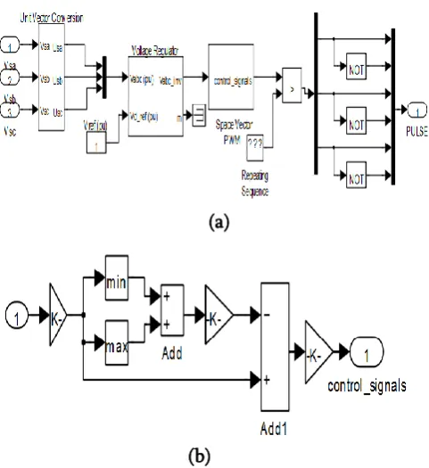
An appropriate control scheme is needed to cope up with uncertainties in the network different operating conditions due to the load/ parameters variations. Space Vector Modulation (SVM) was formerly evolved as vector approach to PWM for three phase inverters. Triangular carrier pulse width modulation is an advanced and more revolutionary approach for generating sinusoidal waveform that offers a higher voltage to the load with lower THD [10]. The main objective of any modulation method is to get variable output having maximum value of fundamental component along with desired harmonics. The triangular carrier based SVM method is implemented by user defined subsystems. These are shown in Fig.2.
In triangular carrier based pulse width modulation, rather than using a separate modulator for each of the phases, the complex reference voltage vector is processed as a whole. Space vector PWM can be easily implemented in digital signal processor [11] which has increased its uses in the last decade. In conventional SVM, synthesis of the output voltage is achieved by chosen the appropriate states of VSI switches and their time slot in such a way that the output voltage is best approximated. Quick implementation of SVM is possible by using triangular carrier based pulse width modulation. It is easy in implementation as sector determination is not required in carrier based PWM. The pulses can be generated by comparing duty ratio profile with high frequency triangular carrier similar to sinusoidal pulse width modulation.
(a)
(b)
Figure 2. (a) Simulation block diagram for SVM to generate gate pulse (b) SVM control signal generator
for triangular carrier based SVM
V. RESULTS AND DISCUSSIONS
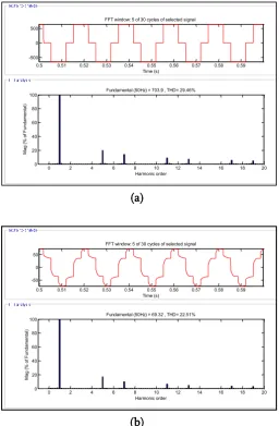
Simulation results for WECS in steady state condition are shown in Fig.3 (a)-(e). Generator voltage ( ), generator current ( ), DC-link voltage ( ), source current ( ) and load current ( ) waveforms for „A‟ phase are shown in Fig.3 at steady state condition. Various voltage and current waveforms and their frequency spectrums are shown in Fig.4 Total harmonic distortions in voltage waveform are reduced from 29.46 % on generator side to 0.86 % on power electronic (rectifier-inverter) interface output after filter, while the current output from the generator having THD of 22.51% improves to the current at power electronic interface output after filter with THD 3.35 %. The notches in current waveform are the result of creeping in DC-link voltage which may be further reduced by advanced tuning of controller parameters.
reducing the generator voltage harmonics. Hence, fulfills the requirement of IEEE Standards.
(a)
(b)
(c)
(d)
(e)
Figure 3. (a) Generator voltage (b) generator current (c) DC-link voltage (d) inverter current
(e) load current
(a)
(b)
Figure 4. Frequency spectrum of (a) generator voltage Vg (b) generator current Ig
(c)
0.5 0.51 0.52 0.53 0.54 0.55 0.56 0.57 0.58 0.59 -500
0 500
FFT window: 5 of 30 cycles of selected signal
Time (s)
0 2 4 6 8 10 12 14 16 18 20
0 20 40 60 80 100
Harmonic order Fundamental (50Hz) = 703.9 , THD= 29.46%
M
a
g
(
%
o
f F
u
n
d
a
m
e
n
ta
l)
0.5 0.51 0.52 0.53 0.54 0.55 0.56 0.57 0.58 0.59 -50
0 50
FFT window: 5 of 30 cycles of selected signal
Time (s)
0 2 4 6 8 10 12 14 16 18 20
0 20 40 60 80 100
Harmonic order Fundamental (50Hz) = 69.32 , THD= 22.51%
M
a
g
(
%
o
f F
u
n
d
a
m
e
n
ta
l)
0.5 0.51 0.52 0.53 0.54 0.55 0.56 0.57 0.58 0.59 -20
0 20
FFT window: 5 of 30 cycles of selected signal
Time (s)
0 2 4 6 8 10 12 14 16 18 20
0 20 40 60 80 100
Harmonic order Fundamental (50Hz) = 32.54 , THD= 0.86%
M
a
g
(
%
o
f F
u
n
d
a
m
e
n
ta
International Journal of Scientific Research in Science, Engineering and Technology (www.ijsrset.com) (d)
Fig. 4(c) source voltage and (d) source current at WECS
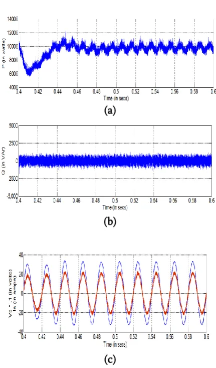
(a)
(b)
(c)
Figure 5. (a) Instantaneous active power P, (b) reactive power Q and (c) source voltage and source current
at WECS
Table 1 enlists the performance of switching scheme used for generating pulses for voltage source
inverters to provide controlled output. The performance of WECS is better in triangular carrier based SVM in terms of %THD in source current and source voltage, both are under the limits in both methods.
Table 1 Summary of various components for WECS in RII with triangular carrier based SVM switching
scheme
Component Triangular Carrier
based SVM %THD of Source voltage 0.86 %THD of Source current 3.34 Active Power (W) 9775 Reactive Power (VAr) 129 DC-link voltage variation (V)
625 - 630
Power factor 0.9999
VI.CONCLUSION
Use of power electronics interface is essential between the generator and grid/load to convert the variable generated output to constant voltage and frequency to feed to grid/load. This paper presents the performance of a WECS with RII connected to a stand-alone load. The effectiveness of applied modulation method is discussed on the basis of total harmonic distortion in voltage and current waveforms, variation in dc–link voltage, reactive power compensation and power factor of the system. It is observed that triangular carrier PWM have better utilization of the dc-link voltage, low current ripple and relatively easy to implement in hardware. It is concluded that triangular carrier pulse width modulation control method works well in stand-alone WECS. Triangular carrier pulse width modulation is more sophisticated, and it gives more voltage output. Thus, DC voltage utilization is increased by using above method.
III.
REFERENCES0.5 0.51 0.52 0.53 0.54 0.55 0.56 0.57 0.58 0.59 -20
-10 0 10 20
FFT window: 5 of 30 cycles of selected signal
Time (s)
0 2 4 6 8 10 12 14 16 18 20
0 20 40 60 80 100
Harmonic order Fundamental (50Hz) = 20.3 , THD= 3.35%
M
a
g
(
%
o
f F
u
n
d
a
m
e
n
ta
[1] Mohod, S.W.; Aware, M.V., "Grid Power Quality with Variable Speed Wind Energy Conversion," Power Electronics, Drives and Energy Systems, 2006. PEDES '06. International Conference on , vol., no., pp.1,5, 12-15 Dec. 2006
[2] Blaabjerg, F.; Iov, F.; Chen, Z.; Ma, K., "Power electronics and controls for wind turbine systems," Energy Conference and Exhibition (EnergyCon),2010 IEEE International Conference , pp.333-344, 18-22 Dec. 2010 [3] Yo-Han Lee; Dong-Hyun Kim; Dong-seok
Hyun, "Carrier based SVPWM method for multi-level system with reduced HDF [ harmonic distortion factor]," Industry Applications Conference, 2000. Conference Record of the 2000 IEEE, vol.3, pp.1996-2003, 2000.
[4] Errami, Y.; Maaroufi, M.; Ouassaid, M., "Modelling and control strategy of PMSG based variable speed wind energy conversion system," International Conference on Multimedia Computing and Systems (ICMCS), 2011, vol., no., pp.1,6, 7-9 April 2011
[5] Chowdhury, B. H.; Chellapilla S., “Double-fed induction generator control for variable speed wind power generation,” Electric Power Systems Research, vol.76, no.9, pp.786-800, jun. 2006.
[6] Chen, Z.; Spooner, E., "Grid interface options for variable-speed, permanent-magnet generators," Electric Power Applications, IEE Proceedings - , vol.145, no.4, pp.273-283, Jul 1998
[7] Singh, B.; Kasal, G.K., "Solid State Voltage and Frequency Controller for a Stand Alone Wind Power Generating System," Power Electronics, IEEE Transactions on , vol.23, no.3, pp.1170,1177, May 2008
[8] Orlando, N.A.; Liserre, M.; Mastromauro, R.A.; Dell'Aquila, A., "A Survey of Control Issues in PMSG-Based Small Wind-Turbine Systems," Industrial Informatics, IEEE Transactions on, vol.9, no.3, pp.1211-1221, Aug. 2013
[9] Jain, B.; Jain, T,; Jain, S.; Nema, R.K., “Power Quality Improvement of an Isolated Wind Power Generation System,” Electrical and Electronics Engineering, IOSR Journal of , vol. 9, no. 3, pp. 33-50, May– Jun. 2014.
[10] Gupta, A.K.; Khambadkone, A.M., "A Space Vector PWM Scheme for Multilevel Inverters Based on Two-Level Space Vector PWM," Industrial Electronics, IEEE Transactions on , vol.53, no.5, pp.1631-1639, Oct. 2006