Volume-7 Issue-1
International Journal of Intellectual Advancements
and Research in Engineering Computations
Automatic LED Street Lights Controller – Design and Implementation
G.Neelamegam
1, G.Bharathi
1, S.Chandru
1, P.M.Manikandan
21
UG Scholar, Department of Electrical and Electronics Engineering
Muthayammal Engineering College,Rasipuram
2
Assistant Professor, Department of Electrical and Electronics Engineering
Muthayammal Engineering College,Rasipuram
ABSTRACT
The main objective of this paper is to form an intelligent street lighting system. In early days, the street lights are controlled manually. Avoid the manpower we have to introduce this easy technique. The newly proposed system offer higher efficiency and considerable savings in power by using LED lights. So there was much more power consumptions. Now a day, street light monitoring system is an essential factor. So we need to design and implement solar based street lighting system for low power usage. In each lamp are connected together and controlled by nearby base station. The street lamp contains several modules like LDR Sensor, PIR Sensor and Relay, which are work together and transfer information to the base station via NRF modules. Here the LDR sensor used to capture the day/Night lighting value. And the PIR sensor used to sense the human/vehicle presence on particular range. Based on those techniques the system controls the street lights. Through the communication networks the base station takes a corresponding action
When the intensity of light becomes low that time necessary of the street lighting. All these information will pass to the base station via NRF devices. From the base station a messages passing to the microcontroller to glow the street lights according to the intensity of light. And also movement based information send to the base station for corresponding action by the controller.
INTRODUCTION
The whole system work is based on the sensors presence. The main idea behind the system is that the LED light will be in off position at day time. Even at day time if the intensity of light is lower due to weather conditions like fog, thunderstorm etc. then the light will get turned on. When PIR sensor detects the vehicles, the brightness of the LED will be high. When there is no vehicle, brightness will be low. This is done, so as to minimize the power usage. Here turned on lights only when it is needed. At night sometimes roads will be empty and hence there is no use of illuminating all the lamps. So we can lower the intensity of LEDs and can conserve more power. At present, street lamps control at most of the urban is only by manual
control, which is inefficient and a waste of manpower, change the resistance by using of light-sensitive device to control street lamps light up automatically in the evening after dark, turn off automatically after dawn in the morning, but the low reliability of the method, vulnerable to interference, night street lighting is too bright and are a waste of energy and other issues;
Time-control method (that is, from time to time opening and closing control).
This method achieved automatic control of street light, thereby reducing the labour intensity and lowering labour costs and improving the efficiency of street lighting control.
Automation, Power consumption and Cost Effectiveness are the important considerations
in the present field of electronics and electrical related technologies.
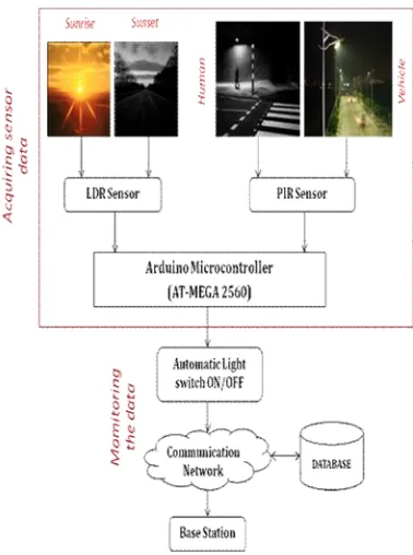
Figure 1: Automatic lighting system working
Figure2 shows the whole system design. They have two parts as, 1) Sensor data acquisition, 2) Monitoring the system. The first part we need two sensors (LDR,PIR) for sensing the environment. And second one
needs communication network modules.
PROPOSED SYSTEM
The proposed system consists of PIR Sensor, LDR Sensor and Arduino microcontroller and so on. The passive infrared sensor measures the infrared light emits from objects in its field of view. The front side of the sensor will have receiver face, through which the infrared light enters to the sensor. It is made up of piezoelectric materials which can detect the level of infrared radiation. When a high signal is reached to the transistor microcontroller that informed the objects is detected.
Intensity control is also possible by Pulse
microcontroller. Sensors used on both side of the road to sense vehicle/human movement, then send logic commands to the microcontroller, which activate the LEDs on or off. Thus, this the way of dynamically changing intensity helps in saving a lot of energy. The project uses an Arduino AT-MEGA 2560 microcontroller. An LDR is used to sense the day or night conditions that enable the power supply to street light only in the night time. No need of light when at late night and also no movement in road. The main aim of this project is,
To monitor and control the status of all street lights Communication Network is used for data
transmission.
Figure 2: Proposed system design
The LDR circuit have a resistor are act as a voltage divider. A LDR Sensor is made of a semiconductor that absorbs photons and based on the quantity and frequency of the absorbed photons, the electrons will gain enough energy to jump into the conduction band. Thus the resulting free electrons conduct electricity that causes reducing resistance of the Light Dependent Resistor Sensor.
PWM is required mainly for intensity controlling of led. LDR is a light dependent resistor which is having very high resistance. This kind of sensor is commonly used in light sensor circuits in open areas, to control street lamps. This LDR mainly used to capture different light values like; day and night lights. LDR gives the discrete output of the resistance values. Based on that value we have to switching the LED lights.
DEVICES AND METHODS
The proposed system consists of a group of modules, monitoring station and one base station typically placed in a building located nearby and it is a modular system easily extendable.
Monitoring Stations
The monitoring station consists of several modules such as PIR Sensor, LDR Sensor, Arduino and Relay is work together and transforms information to the microcontroller.
PIR Sensor
Figure 3: PIR Sensor circuit
The construction of the PIR sensor defines the infrared lights enters through the front of the sensor, is called “sensor face”. At the core of a PIR sensor is a solid state sensor is made up of a piezoelectric material which generates energy when exposed to heat. Materials commonly used in PIR sensors include gallium nitride. The operating principle of the PIR sensor gives an idea that all the objects with temperature above absolute zero emit heat energy in the form of radiation. This radiation is invisible to human eye because it radiates at infrared wavelength, but it can be detected by electronic devices designed for such a purpose. The term passive refers to the
fact that PIR sensors do not generate or radiate any energy for detection purposes and they are working based on the energy emitted from other objects.
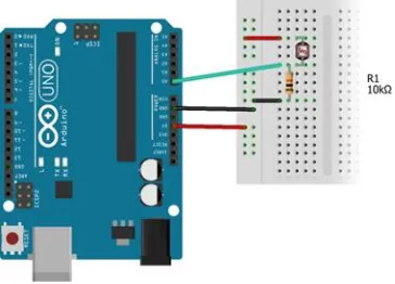
LDR Sensor
Here we are using a light sensor that is the photoconductive light sensor which does not produce electricity but simply changes its physical properties when subjected to light energy. LDR Sensor changes its electrical resistance in response to change in the light sensor.
Figure 4: LDR Sensor circuit
The light dependent resistor is made up of a semiconductor material like cadmium sulphide that changes its electrical resistance from several thousand ohms in the dark to only a few hundred ohms when light falls upon it. Basically light sensor is a resistor which has a resistance that varies depending of the light intensity.
AT-MEGA 2560
The Mega 2560 is a microcontroller board based on the ATmega2560. It has 54 digital input/output pins (of which 15 can be used as PWM outputs), 16
Figure 5: Arduino microcontroller board.
It contains everything needed to support the microcontroller; simply connect it to a computer with a USB cable or power it with a AC-to-DC adapter or battery to get started. The Mega 2560 board is compatible with most shields designed for the Uno and the former boards Duemilanove or Diecimila.
Pulse Width Modulation (PWM)
IR sensor senses the vehicles on the street gives signal to the microcontroller. When vehicles are present it gives bright light. During late night low traffic density so brightness of the LED are automatically lowered .this dimmed light is enough for pedestrian. here also lot of the
power conserved and we can utilize this power other purposes.
Controlling Station
The controlling station has an Ethernet shield and NRF module. That sends all sensed data to the base station. That’s the way the controller takes an appropriate action.
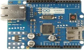
Ethernet Shield
The Arduino Ethernet Shield allows an Arduino board to connect to the internet. It is based on the Wiznet W5100 Ethernet chip. The Wiznet W5100 provides a network (IP) stack capable of both TCP and UDP. It supports up to four simultaneous socket connections.
Figure 6: Arduino Ethernet Shield
Use the Ethernet library to write sketches which connect to the internet using the shield.
NRF Modules
The NRF2L401 Wireless PC Data Transmission System works under DC5V voltage and uses the NRF24L01 Wireless Module to do communication. It can finish the bidirectional transmission through the serial module and the
Figure 7: NRF Module Circuit Diagram
The nRF24L01 is a single chip 2.4GHz transceiver with an embedded baseband protocol engine. It designed for ultra low power wireless applications. The nRF24L01 is designed for operation in the world wide ISM frequency band at 2.400 - 2.4835GHz.
SYSTEM MODULES
The architecture with 4 modules likes Acquiring Sensors Data, Automatic On / Off, Data Transmission, Data Storage. They have to
sense the environment, based on that turn the light on/off.
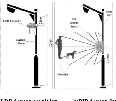
Sensors Data Acquisition
Here all the sensors are kept in streetlights. a) LDR sensor is used to measure the brightness and then b) PIR sensor is used to detect the motion of a human / object.
a)LDR Sensor acquit ion b)PIR Sensor data acquit ion
Figure 8: Shows the acquisition of sensor data
These sensors are connected to the arduino microcontroller board. They continuously produce the values, which are stored into the database for the future use.
Automatic On/Off
Otherwise it is in off condition. This is the way we have to reduce the power usage.
Data Transmission
The sensor data are transmitted from end device to coordinator through communication network. The data is sent periodically. The delay can be set. Here using NRF wireless modules for data transmission.
Data Storage
All of the sensed data is stored into the database. In this data includes the date and time
of the light getting turned on/off. That was accessible by authorized people. It’s very helpful for security purposes.
RESULTS
The PIR Sensor will helpful to detect the presence of human. When they detect obstacle, that information will send to the microcontroller. Next step we have to measure the intensity level of light by using the LDR Sensor.
For measuring the intensity of the light, here we are using LDR sensor shown in figure9 .
Figure 9: LDR sensor working module
In day time intensity of light will be high, so no need of light system. When the intensity of light is low, that time necessary of the street lighting. These are the input modules are work
together to give a result to arduino. From the arduino microcontroller board the information will be passes to the base station through NRF communication devices.
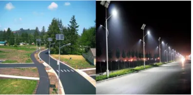
Figure 10: Real time experimental result
This is the implementation result of the street lighting system. These systems will helpful to
conditions to verify the overall functionality and seek better performance.
From the base station also we have to control the light system. That shows in figure 11. Intensity
of the street light can be controlled and we can conserve power effectively. Figure shows the webpage controller screen.
Figure 11: LED controlled form webpage
The above specified LED control system is based on their LDR and PIR sensor values.
We automated the street lights. It reduces the labour charge and then switching is done manually there is no need of human resource.
CONCLUSION
This paper gives a new intelligent street lighting system that will helpful to the person in any helpless situations. It continuously monitors the sensor modules, if there any problem occurs, it will send information to the corresponding authorized person through the network modules. This system will work automatically so we can increase the lamp lifetime.
A new model is presented in this paper which will reduce the power consumption of the street lighting system about 20-35 % compared to conventional design. Here we are saving lot of power without any wastage. As we know, there is a shortage of power nowadays in everywhere mostly in villages. To overcome those problems, we can provide automatic street lighting with the centralized intelligent systems.
So in future we can design many more advanced technologies to save power.
Acknowledgment
The authors wish to thank the Management and Principal of Mepco Schlenk Engineering College, for the support in carrying out this research work.
REFERENCES
[1]. Michele Magno, Tommaso Polonelli, Luca, and Emanuel Popovici, A Low Cost, Highly Scalable Wireless Sensor Network Solution to Achieve Smart LED Light Control for Green Buildings. IEEE Sensors Journal 15(5), 2015, 2963-2973.
[2]. P.Y. Chen, Y.H. Liu, Y.T. Yau and HC. Lee, Development of an energy efficient street light driving system,
Proc. IEEE Int. Conf. Sustain. Energy Technol..761–764, 2008, 24–27..
[3]. W. Yue, S. Changhong, Z. Xianghong, and Y. Wei, Design of new intelligent street light control system,
[4]. Archana.G, Aishwarya.N, Anitha.J ,Vijay Kumar, Intelligent Street Light System. International Journal of Recent Advances in Engineering and Technology 3, 2015, 16-18.
[5]. Fabio Leccese, Remote-Control System of High Efficiency and Intelligent Street Lighting Using a ZigBee Network of Devices and Sensors. IEEE Transactions on Power Delivery 28(1), 2013, 21-28.
[6]. Dipak A. Mhaske and S. S. Katariya, Smart Street Lighting using a ZigBee & GSM Network for High Efficiency & Reliability. International Journal of Engineering Research & Technology (IJERT) 3(4), 2014 175-179.
[7]. Sharath Patil G.S., Rudresh S.M., Kallendrachari, K.M., Kiran Kumar and Vani H.V., Design and Implementation of Automatic Street Light Control Using Sensors and Solar Panel. Int. Journal of Engineering Research and Appli- cations 5(6) 2015, 79-100
[8]. Gustavo W. Denardin, Carlos H. Barriquello, Alexandre Campos and Ricardo N. Do Pradoan, An Intelligent System for Street Lighting Monitoring and Control. IEEE Conference Paper . 2009, 274-278.