Review
Comparison of Finite Element Methods in Fusion
Welding Processes—A Review
Eva S. V. Marques1, Francisco J. G. Silva1,2 and António B. Pereira1,*
1 TEMA—Centre for Mechanical Technology and Automation, Department of Mechanical Engineering,
University of Aveiro, 3810-193 Aveiro, Portugal; [email protected] (E.S.V.M.); [email protected] (F.J.G.S.)
2 ISEP—School of Engineering, Polytechnic of Porto, 4249-015 Porto, Portugal * Correspondence: [email protected]; Tel.:+351-234-370-830
Received: 18 November 2019; Accepted: 27 December 2019; Published: 2 January 2020
Abstract: Currently, welding processes have become one of the most used methods for joining materials in all kinds of industries, thanks to properties such as high speed and high tensile strength. However, despite these advantages, this type of connection method has some drawbacks, for example, residual stress and structural distortion, mainly due to the process thermal cycles. Structural distortion is one of the major concerns of industrial joining practice. In order to decrease distortion, the variation of welding sequence, direction, and clamping conditions, have been applied through several years, by trial and error tests. However, numerical simulation enables virtual examination of the welding, mainly due to the progress on the numerical methods, which stimulated the research on welding simulation models. These models can cover a wide spectrum of physical and thermal processes occurring during, and after welding. The aim of this paper is to provide wider information about types of finite element method (FEM) in fusion welding processes and to demonstrate the accuracy of FEM models results compared to experimental.
Keywords: welding simulation; finite element method; inherent strain theory; welding distortion
1. Introduction
The thermal cycle imposed by welding processes, directly affects the thermal and mechanical
behavior of materials during the work. High temperature during the process and cooling after the welding imply undesirable strains and stresses in the welded parts. Because of this, it is necessary to know, with high accuracy, the behavior of materials subjected to welding thermal cycles.
To acquire such data, it is required to have not only high knowledge but also access to a vast range of laboratory facilities, focused on the mechanical and thermometallurgical properties of the materials used [1,2].
When the aim of the analysis is to obtain the mechanical effects of welding such as residual stress
and distortions, the easiest approach is to consider the thermal and mechanical link only. The analysis at microstructure scale should be only considered when a study of microstructural aspects, such as the microstructure dependency on temperature and deformation, must be carried out [3,4].
Welding analysis must consider three main coupled fields, which interact as shown in Figure1[3].
Figure 1. Relations in welding simulations, data from [3].
The relations between these fields, are explained by the following sequence:
1. Thermal stresses due to microstructural changes;
2. Elastic/plastic behavior;
3. Phase transformation origins volumetric changes;
4. Microstructural changes are coupled with plastic stresses;
5. Material’s microstructure can influence thermal properties;
6. Phase transformation origins latent heat;
7. Deformation evolution has influence on thermal boundary condition;
8. Plastic and elastic stresses can influence heat generation;
9. Deformations are from microstructural evolution;
10. Phase transformations are influenced by stress;
11. Thermal cycles have a direct link on thermal cycles;
12. Deformations are caused by temperature changes.
The finite element method (FEM) analysis is performed through the following stages:
1. A transient heat transfer simulation is done, determining the temperature data along time in
the nodes. It is obtained from a non-linear thermal analysis;
2. This temperature field is loaded into the simulation and then, a static mechanical analysis is
performed. This transient temperature field is the initial input;
3. The thermal expansion origins the deformation;
4. When temperatures achieve their initial values, the residual stress field is obtained, as a result
of all intermediary analysis steps.
For better understanding, an example of the procedure of a thermomechanical analysis is sequenced in Figure 2. Where data such as meshed geometry, material properties, boundary conditions, and equivalent heat source are inputs into the software to perform the simulation. From this stage, it is possible to have two main simulations occurring: thermal and mechanical analysis. Through these simulations, several results are drawn, including residual distortion and stresses.
Figure 1.Relations in welding simulations, data from [3].
The relations between these fields, are explained by the following sequence:
1. Thermal stresses due to microstructural changes; 2. Elastic/plastic behavior;
3. Phase transformation origins volumetric changes;
4. Microstructural changes are coupled with plastic stresses; 5. Material’s microstructure can influence thermal properties; 6. Phase transformation origins latent heat;
7. Deformation evolution has influence on thermal boundary condition; 8. Plastic and elastic stresses can influence heat generation;
9. Deformations are from microstructural evolution; 10. Phase transformations are influenced by stress; 11. Thermal cycles have a direct link on thermal cycles; 12. Deformations are caused by temperature changes.
The finite element method (FEM) analysis is performed through the following stages:
1. A transient heat transfer simulation is done, determining the temperature data along time in the nodes. It is obtained from a non-linear thermal analysis;
2. This temperature field is loaded into the simulation and then, a static mechanical analysis is performed. This transient temperature field is the initial input;
3. The thermal expansion origins the deformation;
4. When temperatures achieve their initial values, the residual stress field is obtained, as a result of all intermediary analysis steps.
Figure 2. Diagram of the welding simulation procedure. Reproduced from [5], with permission from Elsevier, 2019.
2. Models
Complex models (thermomechanical-metallurgical and thermomechanical models) (Figure 3) have more variables into account; therefore, they potentially have higher precision, but are very time-consuming. On the other hand, simplified models are less accurate but considerable faster. All models must be calibrated, validated, and require high knowledge about the physics of the welding process. Below in Figure 3, these models are presented.
Figure 3. Types of models in finite element method (FEM) analysis, data from [6].
2.1. Thermomechanical-Metallurgical Models
In these models, several physical events during welding are considered, as there is elastoplastic material behavior in the parent material, viscosity behavior in the molten zone, phase transformation in the weld seam and in the heat affected zone (HAZ) [7].
2.2. Thermomechanical Models
Figure 2.Diagram of the welding simulation procedure. Reproduced from [5], with permission from Elsevier, 2019.
2. Models
Complex models (thermomechanical-metallurgical and thermomechanical models) (Figure3) have more variables into account; therefore, they potentially have higher precision, but are very time-consuming. On the other hand, simplified models are less accurate but considerable faster. All models must be calibrated, validated, and require high knowledge about the physics of the welding process. Below in Figure3, these models are presented.
Figure 2. Diagram of the welding simulation procedure. Reproduced from [5], with permission from Elsevier, 2019.
2. Models
Complex models (thermomechanical-metallurgical and thermomechanical models) (Figure 3) have more variables into account; therefore, they potentially have higher precision, but are very time-consuming. On the other hand, simplified models are less accurate but considerable faster. All models must be calibrated, validated, and require high knowledge about the physics of the welding process. Below in Figure 3, these models are presented.
Figure 3. Types of models in finite element method (FEM) analysis, data from [6].
2.1. Thermomechanical-Metallurgical Models
In these models, several physical events during welding are considered, as there is elastoplastic material behavior in the parent material, viscosity behavior in the molten zone, phase transformation in the weld seam and in the heat affected zone (HAZ) [7].
2.2. Thermomechanical Models
Figure 3.Types of models in finite element method (FEM) analysis, data from [6].
2.1. Thermomechanical-Metallurgical Models
2.2. Thermomechanical Models
If the material data and phase dependent parameters are not available, the welding simulation can be performed with typical models while ignoring metallurgical effects. Thermal and mechanical
simulations can be sequentially performed at each step, storing the intermediate temperature values. The convergence behavior of the coupled transient simulation is more sensitive than the sequential computation, therefore, it does not bring considerable time advantage. Since this model has a poorer physical background, it does not have so many chances to predict the residual stresses in the weld [6].
2.3. Simplified Mechanical Models
These models disregard transient thermomechanical history in contrast to the previously mentioned models. They imply only a mechanical computation and no thermal simulation; they are based on elastoplastic material behavior [8] and consider material shrinkage after welding as the primary cause of distortion. These models can correctly predict the distorted shape of the part, and they are also able to apply quantitative distortion prediction.
Table1shows a summary of the differences between these models, and Table2shows a summary
about differences between the sub-models of simplified mechanical models.
Table 1.Comparison between models [6].
Model Material Data ComputationTime Applicability Quality
Thermomechanical-metallurgical models
Temperature dependent material data, Young’s
modulus, yield stress Very high Research
Certain—If the material data is available. Uncertain- if the material data is not available and is calculated by extrapolation.
Thermomechanical models dependent material data.No need of temperature High Research andIndustry
Efficient to predict the correct distortion. Only the average stress level
can be evaluated.
Simplified mechanical models dependent material data.No need of temperature Low Research andIndustry Efficorrect distortion.cient to predict the
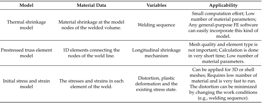
Table 2.Differences between the simplified mechanical models.
Model Material Data Variables Applicability
Thermal shrinkage
model Material shrinkage at the modelnodes of the welded volume. Welding sequence
Small computation effort; Low number of material parameters; Any general-purpose FE software can easily incorporate this kind of
model.
Prestressed truss element
model 1D elements connecting thenodes of the weld line. Longitudinal shrinkagemechanism
Mesh quality and element type is not important; Calculation is done in very short time; Low number of
material parameters.
Initial stress and strain
model The stresses and strains in eachelement of the weld.
Distortion, plastic deformation and the
existing stress state.
Can be applied for 3D or shell meshes; Requires low number of
material and is very fast to run. The distortion can be minimized by changing the work conditions
(e.g., welding sequence).
As written before, simplified mechanical models are divided in the sub-models below.
2.4. Thermal Shrinkage Model
through all the nodes, the part is released, and the distortion calculated. More detailed works about this subject can be verified in Khurram et al. [9] and Barsoum et al. [10].
2.5. Prestressed Truss Element Model
The 1D elements get the initial stress, which causes their shrinkage, which in many cases is the dominant distortion mode. Transversal elements can also be incorporated in the weld to consider the transversal shrinkage [11]. However, it becomes a more complex model, and the elements of the parts to be merged must have an elastoplastic behavior. The model also produces realistic distortion data, even if both the simulations are purely elastic.
2.6. Initial Stress and Strain Model
An important issue for all fast models to calculate distortion, the parameters must be realistic. Usually, to achieve good results, the material properties of the molten zone must be similar to the real ones. Again, proper calibration of the model must be done to obtain good quality results in terms of distortion. [6].
3. Stages of FEM Analysis
3.1. Thermal and Heat Source Analysis
The calculation of the values of welding stresses, strains, and temperature distribution is very difficult, due to the strong connection between temperature, shrinkage, thermal expansion, and material
properties. With the objective to make the analysis simplest, thermal and mechanical states are usually analyzed in another step. This method is uttered by the principle that the mechanical properties such as stresses and strains, do not promote alteration of temperature, but the opposite, i.e., a change in temperature, for sure has impact in the strain and stress fields.
Because of this, the simulation of a welding process is connected to the temperature field existing in the welding process. This type of analysis assumes that heat generated during plastic deformation is negligible compared to the heat supplied by the welding equipment. In this sense, it is possible to perform thermal and mechanical analysis as two sequentially simulation analyses [6–12].
Another crucial issue in numerical analysis is the way of describing how heat is supplied to a welded joint. Referenced publications related to the numerical modeling of welding processes contain, among others, the 2D-Gaussian surface heat source model (2D Gauss), the double-ellipsoidal heat source (Goldak’s model), or the 3-D Gaussian conical heat source model. Each of these sources have their own application in modeling a specific welding process or heat treatment [6–12].
3.1.1. 2D Gaussian Surface Heat Source Model (2D Gauss)
This simulation method uses a surface heat source to model, as example, heat treatment work, manual metal arc welding, among other processes.
3.1.2. Double-Ellipsoidal Heat Source Model (Goldak’s Model)
This model proves to be useful is situations where a process is carried out using “melting in welding”, and the possibilities of changing the shape of a model, enabling its adjustment to a specific welding method, mainly arc welding. To simulate this case, the front and rear ellipsoid should be calibrated and fitted separately with the help of macrograph data, and by this way, it is possible to obtain numerical results for deep penetration welding. The heat input (Q), is given by Equation (1), whereηis the welding efficiency,Uthe welding voltage, andIthe welding current:
Q = ηUI
The heat source model may be described in Equation (2):
qf(x, y, z) = Q0,fe−3x
2 a2)e −3
y2 b2)e −3
z2 c f2
!
, (2)
whereqf: heat source density of the front ellipsoid;a: half width of the heat source model;b: penetration; cf: length of the front ellipsoid.
3.1.3. 3D-Gaussian Conical Heat Source Model
This conical shape model is more realistic for welding works characterized by high energy and deep penetration, such as electron beam or laser welding. The heat density of this model is given by Equation (3):
Q(r, y) = Q0e−3r2/r0(y) 2
, (3)
wherer: current radius from the center of the heat source;r0(y)=radius of heat source atz.
The calculation for the rear ellipsoid is done by changing the indices demonstrated in [12].Q0and Q0,fmust be standardized while the thermal analysis is still occurring, to ensure that the heat input is equal toQgiven in Equation (1).
3.1.4. Uniform Surface Heat Flux
Uniform surface heat flux (USHF) [13] is a simpler and quicker alternative such as the 3D-Gaussian conical heat source model. The weld power is calculated using the welding parameters in Equation (4). The USHF value is defined by Equation (5):
Q = ηU I, (4)
whereη: thermal efficiency factor;U: arc voltage;I: welding current.
Q
TS·R·√2·lw, (5)
whereTS: travel speed;R: ramp ratio;lw: leg length of the weld.
Further work with this method can be consulted in Aalami-Aleagha et al. [14], Armentani et al. [15], and Sepe et al. [16].
3.2. Thermal Material Model
The heating and cooling rates occurred in the HAZ, have a huge influence on phase transformation [17,18].
Thermal conductivity is one of the most important properties in the numerical processes, since it has the same role in the finite element method as the Young’s modulus in structural analysis, because it defines the stiffness matrix of the thermal simulation.
3.3. Mechanical Boundary Conditions
In the matter of fact of mechanical analysis, the clamping conditions have a major influence on the origins and evolution of deformations [18]. Changing the time of unclamping, or the positions of the clamps, has direct influence on these stresses. It is important to reflect that the stiffer the clamping
conditions are in proper gigs, the smaller the induced stresses and deformations are.
3.4. Mechanical Material Properties
The following material properties must be used to the numerical simulation: Poisson’s ratio, thermal strain, Young’s modulus, yield strength, and stress-strain curves. It is common knowledge that elements with small toughness can cause element distortion problems. Therefore, these elements must be avoided during the analysis if their temperature is above the zero strength temperature (ZST).
If the element cools below the ZST, it will be activated, and its stress–strain result is started from zero again. After the activation, the reference temperature is changed from room temperature to ZST. This calculation technique is called the “birth and death” method [19–21]. Further information about this technique can be seen on [22,23].
Welding leads to thermal cycles in the welded volume and heat affected zone, therefore, in some
cases, kinematic hardening analysis should be applied, especially in fatigue situation [23–25].
4. Inherent Deformation Theory
Aiming to obtain the welding distortion of large welding structure, many studies were done on the simplified numerical simulation method of welding [26–30]. This originated the inherent deformation theory. Although this method cannot simulate every step of the welding process, it can solve complex engineering problems and easily predict welding distortion.
While the uniform movement of the heat source, in a certain distance since the start to the edge of the plate is given, elastic, plastic, thermal, and creep strains are generated by heat input and are to be expected to be uniform along the welded line. The elastic component of these strains is reversible and is removed after cooling; however, plastic, creep, and thermal parts of the strain remain, and their sum is defined as the inherent strain [31], which is expressed by Equation (4):
εtotal−εelastic=εthermal+εcreep+εplastic=εinherent. (6)
In a welded component, the creep and thermal strains are too small and usually are ignored [32]. Therefore, in welding, the amount of inherent strain in each direction is basically the amount of plastic strain in the same direction, so Equation (4) turns into Equation (5):
εtotal−εelastic=εplastic=εinherent. (7)
These deformations can be calculated for a small part of the structure by its simulation, and then, it can be propagated through the entire structure [33]. However, because it is difficult to apply inherent
strains on the model, it is possible to assume that there is an inherent amount of deformation for each section perpendicular to the welded line.
Lu et al. [34] compared the inherent strains theory with the use of FEM thermo–elastic–plastic analysis, using a T-joint part constituted by a web with 60 mm×60 mm×6 mm and a flange with 100 mm×60 mm×6 mm.
Table 3.Simulation results of FEM analysis and inherent strains method [34].
Distortion Thermo–Elastic–Plastic FEM Inherent Strains Method %Error
Transverse deformation (mm) 0.1410 0.0362 74.32
Longitudinal deformation (mm) 0.05 0.0705 29.07
Angular deformation (mm) 1.06 0.987 6.89
Total deformation (mm) 1.067 0.992 7.02
Farajpour and Ranjbarnodeh [35] studied a dissimilar welded structure that was simulated with 3D solid and shell elements in ANSYS 11.0 finite element software (Ansys, Inc., Canonsburg, PA, USA), to obtain the deformations. Also, the weldment was simulated using an inherent deformation method. Both results were compared to the experimental ones. This comparison showed that it was feasible to simulate a dissimilar welded joint using both methods. The conventional simulation had 9-node solid elements, which needs a large memory as well as a time-consuming analysis. On the other hand, simulation with the inherent deformations uses 4-nodes shell elements, reducing the required memory, consequently saving time and costs of the analysis.
The following results were drawn from this study [35]:
• The experimental weld pool width was 5.6 mm, while the one from the thermal simulation result was 5 mm, showing an 11% error rate;
• Empirical results showed a distortion of 5.85 mm, whereas the analysis from the inherent strains model showed a result of 5 mm (17% error rate);
• This method reduces analysis time by 70%.
Wei et al. [36] proposed a simple and efficient method, to estimate inherent deformation of typical
weld joints by inverse analysis. In this method, the inherent deformation was introduced into the elastic FEM as the initial strain, however, the values of the inherent deformations for all welded joints included in the structure, must be known previously.
Through this work, it was concluded that a good agreement between the predicted (inherent strains theory) and the measured deformations was achieved, which demonstrates that this method can be employed with inverse analysis, in an effective way to predict welding distortions of large
welded plate structures.
5. FEM Software Comparison
Finite element method is very useful for calculating distortion and residual stresses in welded joints, without the need to perform expensive tests. The non-uniform temperature field produced during the welding work gives rise to “impossible” strains, which in turn results in generation of self-equilibrating distribution of residual stresses that stay in the welded structure after cooling. In weld simulation, usual software like ANSYS, ABAQUS, and SYSWELD are used. ANSYS and ABAQUS require complex subroutines programming, whereas SYSWELD is specially designed for welding and heat treatment processes [18].
Tikhomirov et al. [37] performed a comparative analysis for weld distortion in a transverse control arm welded by metal active gas (MAG) process. All data concerning the welding process, such as welding sequence and clamping, were available. The numerical simulation was done using simplified models (Table4) into the ABAQUS 6.5 (Dassault Systèmes, Vélizy-Villacoublay, France) and SYSWELD
2003 (ESI Group, Paris, France) software.
Table 4.SYSWELD vs. other models results [37].
Criteria Shrinkage ModelThermal Prestressed TrussElement Model Initial Stress andStrain Model SYSWELD
Number of material
parameters Small Small Small Large
Preprocessing time required Small Small Small Large
Relative distortion with
respect to the experiment (%) 93 103 96 92
Total computation time 41 s 26 s 13 s 38 h
Kollár et al. [18] developed a study about using ANSYS and SYSWELD for arc and laser welding,
using an uncoupled analysis technique in buckling welding.
The thermal analysis was carried out in both finite element (FE) codes with the same butt-welded plate geometry, FE mesh size, heat source parameters, and boundary conditions. The numerical model considers the most important welding input parameters (welding speed, current, voltage, and efficiency) for arc and laser processes. The results show that the ANSYS and SYSWELD models are in
good agreement with each other.
Caprace et al [5] proposed a benchmark study to understand the influence of modeler’s practice and FEM codes on welding simulation results. This influence may relate to the selection of simulation parameters such as mesh size, material modeling, heat input, boundary conditions, etc. Therefore, the residual stress and distortion of T-joint welding were numerically analyzed under several parameters such as material models, boundary conditions, and heat inputs. Afterward, the results of this simulation were compared with experimental results. It was revealed, through experiments shown in Table5, where two sequential welding was applied, that the modeler practice may have considerable effects
on welding residual stresses up to 20% and have less effect on the welding distortion analysis−12%.
It was noticed, while performing the simulation, that small variations on the material properties combined with small differences from equivalent heat sources may strongly affect the predictability of
the residual stress.
Table 5.Simulation matrix from [5] for two models: Hardening and Equivalent heat source (EHS).
Simulation Software Hardening Model EHS Model
1 Ansys Isotropic USHF
2 Ansys Kinematic USHF
3 Sysweld Isotropic Goldak’s
4 Sysweld Isotropic Goldak’s
5 Virfac Isotropic Goldak’s
6 Abaqus Isotropic Goldak’s
6. FEM Simulation vs. Experimental Results
Stamenkovíc and Vasovíc [38] studied manual metal arc welding (MMAW) of carbon steel plates.
The finite element analysis of residual stresses in butt welding of two similar plates was performed with ANSYS.
Figure 4.Results from study [38], published at Scientific Technical Review, with permission from the authors Ivana Vasovi´c and Dragi Stamenkovic, 2019.
Ding et al. [39] studied the residual stress of the wide butt welds through an 8-experiment test program. The model was developed by SYSWELD, to simulate the residual stress produced by the wide butt welding. The conclusions of this study were the following:
• The FE model underestimates the residual stress in the transverse and longitudinal direction to the welding seam by 7% and 2%, respectively.
• This study demonstrated the existence of high residual stress during the welding process of wide butt-welding seams (Table6).
• While the pattern was similar across different welding widths, the strength of the residual stress
increased when the width of the weld increased.
Table 6.Comparison of FEM analysis and experimental results [39].
Weld Width (mm)
Transverse Residual Stress of Location 1 Longitudinal Residual Stress of Location 1
Test (MPa) Prediction(MPa) Test-to-PredictionRatio Test (MPa) Prediction(MPa) Test-to-PredictionRatio
45 129.3 110.6 1.17 156.4 150.5 1.04
55 161.5 148.7 1.09 194.1 201.2 0.96
65 194.9 190.2 1.02 271.1 264.3 1.03
75 224.8 225.8 0.99 341.5 330.1 1.03
Mean - - 1.07 - - 1.02
Cov - - 0.07 - - 0.03
Zubairuddin et al. [40] investigated the residual stress and distortion induced in 3 mm thick modified 9Cr-1Mo steel plates, using gas tungsten arc welding (GTAW) as a joining process. SYSWELD software was performed for the thermomechanical analysis.
Distortion of the weld joint was measured using vertical electronic height gauge and the finite element analysis of distortion of the weld joint was carried out by applying both large and small distortion theories. Comparison of experimental and numerical results showed better accuracy if large distortion theory was applied.
It can also be concluded that:
• The final temperature distribution using finite element model showed 4.5% error, compared to experimentally measured results;
• The numerically predicted distortion values using large distortion theory were 10–20 times larger than the small distortion theory (Table7).
Figure 4.Results from study [38], published at Scientific Technical Review, with permission from the authors Ivana Vasovi´c and Dragi Stamenkovic, 2019.
Ding et al. [39] studied the residual stress of the wide butt welds through an 8-experiment test program. The model was developed by SYSWELD, to simulate the residual stress produced by the wide butt welding. The conclusions of this study were the following:
• The FE model underestimates the residual stress in the transverse and longitudinal direction to the welding seam by 7% and 2%, respectively.
• This study demonstrated the existence of high residual stress during the welding process of wide butt-welding seams (Table6).
• While the pattern was similar across different welding widths, the strength of the residual stress
increased when the width of the weld increased.
Table 6.Comparison of FEM analysis and experimental results [39].
Weld Width (mm)
Transverse Residual Stress of Location 1 Longitudinal Residual Stress of Location 1
Test (MPa) Prediction(MPa) Test-to-PredictionRatio Test (MPa) Prediction(MPa) Test-to-PredictionRatio
45 129.3 110.6 1.17 156.4 150.5 1.04
55 161.5 148.7 1.09 194.1 201.2 0.96
65 194.9 190.2 1.02 271.1 264.3 1.03
75 224.8 225.8 0.99 341.5 330.1 1.03
Mean - - 1.07 - - 1.02
Cov - - 0.07 - - 0.03
Zubairuddin et al. [40] investigated the residual stress and distortion induced in 3 mm thick modified 9Cr-1Mo steel plates, using gas tungsten arc welding (GTAW) as a joining process. SYSWELD software was performed for the thermomechanical analysis.
Distortion of the weld joint was measured using vertical electronic height gauge and the finite element analysis of distortion of the weld joint was carried out by applying both large and small distortion theories. Comparison of experimental and numerical results showed better accuracy if large distortion theory was applied.
It can also be concluded that:
• The final temperature distribution using finite element model showed 4.5% error, compared to experimentally measured results;
Table 7.Differences between large and small distortion theory [40].
Position Experimental Large Distortion Theory Small Distortion Theory
Line 1 3.91 3.88 0.26
Line 2 3.4 3.75 0.28
Line 3 5.35 5.58 0.268
Kik and Górka [41] investigated numerical simulations based on the real experiments of S700MC
steel T-joint laser and hybrid welding. The simulation was carried out with SYSWELD. Some variables such as the distribution of temperature fields, thermal cycles, distributions of individual metallurgical phases and hardness, strains, and plastic deformations were calculated for one selected joint from both mentioned methods. The main objective was to determine the differences in the stress distributions,
and their minimal and maximal values. The results of the experiment showed that after the calibration of heat source models, it was possible to obtain results of thermometallurgical analyses with a good agreement with the experimental test results. It was also possible to have other information such as:
• Metallurgical phases and cooling rates were reflected in the hardness distributions;
• The concentration of martensite influenced the von Mises stress values;
• The values in the laser welding were higher 50 MPa, than the hybrid welding case;
• The maximum stress values were concentrated in the HAZ, for both welding processes;
• Areas subjected to strains were influenced by the thermal cycles.
Pavani et al. [42] studied manual metal arc welding (MMAW) process of carbon steel plates. The finite element analysis was performed by ANSYS software. The welding simulation considered a sequential coupled thermostructural analysis and the element birth and death method were applied. It was observed that the stress, in the direction of the width of the test plate, has the highest influence on the formation of cold cracks. The instantaneous stress on the weld surface was 800–1000 MPa, and below the weld was 500–600 MPa.
Dean et al. [43] investigated the effects of solid-state phase transformation on residual stresses and
deformations in low and medium carbon steels, welded by tungsten inert gas (TIG) arc welding process. In this study, continuous cooling transformation (CCT) diagrams were used to predict the fractions of martensite in the HAZ. The analysis of low carbon steel revealed that the residual stresses and distortions did not seem to be affected by phase transformation during cooling. However, for medium
carbon steel, the residual stresses and deformation were significantly affected by the low-temperature
phase transformation.
Seles et al. [44] presented a paper about a finite element procedure for the prediction of welding-induced residual stresses and distortions in large structures, using an arranged temperature approach considered in ABAQUS software. To validate the results obtained from this method, two numerical samples were tested: one was a butt-welding of two plates and the other a T-joint fillet. The technique of birth and death was applied, and a comparison with experimental results was done, demonstrating a good agreement between the heat generation rate approach as well as the experimental measurements.
Lei et al. [45] studied the characteristics of residual stresses, using a finite element method, on a dissimilar welded pipe with the following type of steels: T92 and S30432. It was also studied in this paper, the effects of heat input, layer number, and groove shape on the residual stress distribution to
Table 8.Results from [45].
Position Groove Angle Decreased Layer Number Increased andLess Heat Input
T92 side Great reduction in the peak valuesof the hoop and axial stress Little effect
S30432 side Little effect residual stress was decreasedThe peak value of the tensile
Dhinakaran et al. [46] studied autogenous plasma arc welding of thin titanium alloy with 2 mm thickness, by numerical and experimental tests. The finite element code COMSOL multiphysics (COMSOL Inc., Stockholm, Sweden) was applied to perform non-linear instable heat transfer analysis using parabolic Gaussian heat source. Some variables such as thermal conductivity, density, and specific heat were used to improve the efficiency of the simulation process. The experimental tests
were directed by varying the welding speed and current using Fronius plasma arc. The simulation and experimental results were in good agreement between them.
Belitzki et al. [47], in his experience, developed a method to minimize distortions caused by laser beam welding. This method consisted of using a meta-model by means of an artificial neural network to predict local distortions in a complex structure, depending on several welding parameters. In this model, a genetic algorithm was used to find the suitable parameters of laser welding in this specific structure. A thermomechanical simulation was performed by SYSWELD software, whereby it was concluded that this method was reliable in identifying optimized welding parameters and predicting distortions.
Chukkan et al. [48] developed a methodology to verify the state of residual stress in a butt-welded plate by using neutron diffraction for measurements. The measured residual stress was used to estimate
the stress distribution, which was mapped by FEM on a weld plate. It was shown that precise residual stress field reconstruction was possible, in and around the area of measurement. It was concluded that the mapping method was a simple and computationally efficient technique for the prediction of the
global residual stress field, especially for fracture and fatigue analysis.
Zhang et al. [49] studied the prediction of distortions using a full-size element model, performed by ABAQUS in a 1/8 VV, which is a vacuum vessel highly used in China. To study the distortions, three
different tungsten inert gas (TIG) welding sequences were simulated on this vessel. Through this paper,
it was possible to verify that in three different welding sequences, the maximum distortion occurred
on the shells near the transition structures. Since sequence 1 resulted in the minimum welding stress and the lowest distortion among all three, this should be the improved welding sequence to diminish distortions in this material.
Liu et al. [50] studied the simulations and experiments regarding fatigue behavior of the RAFM (reduced activation martensitic/ferritic) steel, which is an important material for future fusion reactor
blankets. The simulation behavior of TIG and electron beam welding (EBW), were carried out by using ANSYS software, using the same gradient load. The experimental results were studied to analyze the impact of fatigue resistance on RAFM steel, and the results indicate that the EB welding was stable under increasing stress.
Rathod et al. [51] studied the influence of the choice of welding processes, and how they can impact the life performance of critical nuclear components such as reactor pressure vessels and steam generators. Welding joints at a thickness of 130 mm were welded in three different processes:
narrow-gap gas tungsten arc (NG-GTAW), narrow-gap submerged arc (NG-SAW), and reduced pressure electron beam welding (RPEBW). Through this experience, it was possible to conclude the following:
• EB welding resulted in the largest HAZ;
• Since it was noted a much higher weld heat input during the filling passes for GTAW, when compared to SAW, there was a bigger distortion;
• Concerning maintaining weld quality, NG-GTAW was the most challenging.
Joshi et al. [52] presented a paper about the numerical measurements of welding-induced distortions in a 4-lacing dragline cluster built in a workshop, performed with GMAW process. It was concluded that welding-induced distortions produced very little dimensional inaccuracies. The utmost deviation seemed to be in the second lacing (4 mm), which would result in reducing the strength and overall load-bearing ability of the joint. To eliminate this inaccuracy, a jig should be constructed.
Kobayashi et al. [53] presented a paper about studying the distortions applied in a complicated structure such as a compressor impeller. This analysis and experiment results have revealed that it is possible to evaluate welding distortion with high accuracy in an impeller by using numerical analysis (heat source model and phase transformations). This study showed that there is an agreement between the numerical and experimental results, revealing that the simulation was accurate. It was possible to see that while radial-direction distortions were not so large, the following distortions displacement of cover height and displacement of discharge width, were.
• Displacement of discharge width caused by angular distortion;
• Displacement of cover height caused by shrinkage along the welding lines.
Bonnaud et al. [54] performed full 3D simulations in studying the start/stop in partial repair effects.
The start and stop events have been simulated in 3D, and comparison, with 2D results, indicate a significant increase in weld residual stresses. These events are harmful to reliability since the extra thermal and mechanical loading increases the stress height, which can influence the crack depth or the initiation of failure.
Pasternak et al. [55] presented a study in which a welded I-girder from two structural steel grades (S355 and S690) was submitted to a numerical simulation in order to verify residual welding stresses. Given the results shown in this paper, simplified models are still in need. Despite its reliability in stress results, and the fact that they are suitable for load-carrying calculation, it needs further studies in matters of civil engineering.
Yuewei et al. [56] investigated the characteristics of welding fiber laser keyhole, using a 3D numerical simulation model and a Gaussian heat source model. Welding parameters under different
process conditions were analyzed through numerical simulation. The validity of this model was confirmed with experimental results.
Derakshshan et al. [57] studied the prediction of residual stresses and distortions in welding thin plate structures, using a 3D thermometallurgical-mechanical model. Three different laser-based
welding processes were tested: autogenous laser welding (ALW), cold wire assisted laser welding (CWLAW), and hybrid laser arc welding (HLAW). These processes were compared with submerged arc welding (SAW) in software and experimental results. For this paper, SYSWELD software was used, in which deformation theories were applied to predict residual stresses and deformations. It was concluded that lower heat input can influence distortion values, which supports the theory that laser welding processes should substitute the arc welding method.
Balram et al. [58] developed an investigation about residual stress in dissimilar TIG weldments of AISI 304 and Monel 400. For this work, a finite element model was created to predict temperature fields and residual stress distribution. For this FEM model, a coupled sequentially thermomechanical transient analysis was applied in ANSYS software. One of the conclusions was that the finite element 3D heat source model was an efficient method to predict with accuracy residual stresses in the weldments.
The predicted results agreed with the experimental ones with a 5% error.
Li et al. [60] performed a finite element analysis to understand multi-layer rotating arc narrow gap MAG welding for medium steel plate. Temperature field was solved and analyzed in multi- layer rotating arc welding based on element birth and death technique. The simulation results were in good agreement with the experimental data, 1.5 mm of difference between them. Residual stress and
deformations were calculated based on temperature fields in four welding conditions. This method is useful for microstructural and welding analysis.
D’Ostuni et al. [61] performed a study in a dissimilar welding butt joint (titanium and aluminum), using a fiber laser welding method. 2D and 3D Gaussian heat source were used to study the thermal analysis of this welding process. The experimental fusion zone of the joint was compared with the numerical one. During the welding cycle, the actual temperature was registered and was validated by the numerical model. To calculate fusion zone’s dimension, the 2D model demonstrated better accuracy than the 3D. Although, the 3D heat source resented better results in the matter of welding pool and cooling rate simulation.
Casalino et al. [62] studied the effects of Yb fiber laser welding method in a 2 mm thickness
AA5754 and Ti6Al4V butt joints. This Yb fiber laser operated on the upper surface of the Ti sheet. To confirm experimental results, a FEM analysis using ANSYS code was performed to support the results from the experimental work. It was possible to verify that the numerical model was accurate, as well as, the thermal behavior and pool shape geometry.
7. FEM Simulation with Post Heat Welding Treatment
Balakrishnan et al. [63] performed analysis in single-sided welds of 30 mm thick plates of SA508 steel, which is the main constituent of safety-critical pressure vessels. This analysis was performed by using four welding processes: gas tungsten arc welding (GTAW), submerged arc welding (SAW), and RPEBW. The residual stress distributions for each welding process was measured in the as-welded condition and after post weld heat treatment (PWHT), using neutron diffraction and the contour
method. Results showed that PWHT was effective in reducing the residual stress that was present in
all-welded samples.
Vasileiou et al. [64] studied the same material such as [51] with the same welding processes, except for the appliance of deep hole drilling and the contour method for measurements. PWHT was also used after measurements of deep hole drilling. Through this paper, it was possible to conclude:
• The RPEB weld created the largest region of tensile longitudinal residual stress;
• Transverse stresses in the RPEB weld were compressive near the top and bottom surfaces;
• Post-weld heat treatment was an effective method in reducing the levels of residual stress that
were present in all weld samples.
Yaghi et al. [65] performed an FE simulation on thermal analysis and a sequentially coupled structural analysis in a P91 steel pipe, with a diameter of 145 mm and a thickness wall of 50 mm. Phase transformation was also considered. The effects of PWHT have been investigated, including the
effects of holding time. The results indicate the importance of including solid-state phase transformation
(SSPT) in the simulation of residual stresses during the welding of P91 steel as well as the significance of PWHT on stress relief. The PWHT holding time has a huge effect in the residual stresses, with more
than half the reduction, during a holding time of 3 h, during the first 30 min.
Mouelle et al. [66] presented a new thermodynamically modeling approach to describe the experience of hardening recovery in metals during annealing. To identify model parameters, it was necessary to perform experimental compressive tests, and heat treatments on 316L austenitic stainless steel. Numerical simulations were performed, to evaluate the qualifications and limitations of the model.
were compared to present weld residual stress improvements. Through comparison, it was possible to conclude that UIT has potential applications on the fatigue design of welded structures, which can lead to lighter structures.
8. Conclusions
Throughout this study, it is possible to conclude that the main advantage of FEM simulations is to save costs and improve the quality of prototyping processes. Even though the computing times are large, it is possible to save time in the industry, since it is possible to get a first product series in conformity with the quality required by the customer, and not resort to last-minute solutions. Furthermore, other conclusions can be redrawn from this paper such as:
• The selection of the model to be used depends on the users need to study. COMSOL has proved to be efficient in predicting heat transfer analyses, while SYSWELD, ABAQUS, and ANSYS have
been often used to predict residual stresses, distortion, and fusion zone’s dimension in several welding processes, since the most conventional ones to advanced welding processes such as EBW and laser welding. Sometimes, the choice of software mainly depends on the preprocessing times and the parameters necessary for the simulation;
• Even presenting differences among the simplified mechanical models used, it is possible to observe
a very good coherence between them. The main differences among them are the input parameters
and the preprocessing time;
• Heat source models may be used depending on which welding process is being simulated. 2D Gaussian is advisable for MMAW, Goldak’s model for arc welding, and 3D-Gaussian or USHF for electron beam or laser welding;
• For larger structures simulation, inherent strains theory may be applied, since it is a simple model based on extrapolations, but it remains very accurate when compared to FEM analysis.
• For smaller structures simulation, FEM analysis is advisable;
• Software like ANSYS or ABAQUS can facilitate the processing of complex models such as thermomechanical models. The use of simplified models such as thermal shrinkage models or pre-stressed truss element models are less time-consuming and still accurate when compared to software results;
• The main difference between these software, is their code and the input data that are requested; • FEM analysis is accurate in all software and when compared to experimental results. By comparing
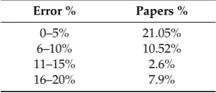
37 papers presented in this work, it was possible to verify that some of them presented an error analysis (%) relatively to the experimental results. It can be seen in Table9, that most of FEM analysis have an error % of 0% to 5%, which can be considered accurate when comparing simulations with experiments. It was also possible to obtain deviations from 11% to 20%, even though in a smaller number.
• This higher deviation can relate to some procedures that are performed during the FEM simulation. It was demonstrated that in these papers, the following methods were used:
◦ “Life and death” method;
◦ Mechanical boundary conditions conjugated with thermal boundary conditions;
◦ Changes in heat equivalent source types and parameters;
• Some problems while performing simulations were also found:
◦ Imprecise alignment of the arc welding;
◦ Use of small variations of thermomechanical material properties combined with differences
of heat equivalent source;
• With FEM analysis, it is possible to simulate PWHT, therefore verify which temperatures can be used to diminish residual stresses and distortion with this treatment;
• It is also possible to achieve very detailed information about the process parameters and results which changed over the processing time, and even the influence of phase transformations in these results;
• Through using numerical simulations, engineers can easily check what will happen when the welding processes parameters are changed.
Table 9.Error % of experimental vs simulation results.
Error % Papers %
0–5% 21.05%
6–10% 10.52%
11–15% 2.6%
16–20% 7.9%
Author Contributions:Conceptualization, A.B.P. and F.J.G.S.; formal analysis, F.J.G.S.; funding acquisition, A.B.P.; investigation, E.S.V.M.; supervision, A.B.P. and F.J.G.S.; writing—original draft, E.S.V.M.; writing—review & editing, A.B.P. and F.J.G.S. All authors have read and agreed to the published version of the manuscript. Funding: This research was funded by Fundação para a Ciencia e a Tecnologia, project number
UID/EMS/00481/2019; Centro Portugal Regional Operational Programme (Centro2020) under the PORTUGAL
2020 Partnership Agreement, project numbers CENTRO-01-0145-FEDER-022083, 33912 AAC 03/SI/2017,
POCI-01-0145-FEDER-032466 and POCI-01-0145-FEDER-032362. Conflicts of Interest:The authors declare no conflict of interest.
References
1. Kik, T. Numerical analysis of MIG welding of butt joints in aluminium alloy.Biul. Inst. Spaw.2014,58, 37–43. 2. Slováˇcek, M.; Kik, T. Use of Welding process numerical analyses as Technical support in industry. part 1:
Introduction to Welding process numerical simulations.Biul. Inst. Spaw. 2015,59, 25–31. [CrossRef] 3. Lindgren, L.-E. Finite Element Modeling and Simulation of Welding. Part 1: Increased Complexity.
J. Therm. Stresses2001,24, 141–192. [CrossRef]
4. Lindgren, L.-E. Finite Element Modeling and Simulation of Welding. Part 2: Improved Material Modeling.
J. Therm. Stresses2001,24, 195–231. [CrossRef]
5. Caprace, J.D.; Fu, G.; Carrara, J.F.; Remes, H.; Shin, S.B. A benchmark study of uncertainness in welding simulation.Mar. Struct.2017,56, 69–84. [CrossRef]
6. Kose, K.; Rietman, B. Combining forming results via weld models to powerful numerical assemblies. In Proceedings of the 7th ESAFORM Conference on Material Forming, Trondheim, Norway, 28–30 April 2004. 7. Rietman, B.; Kose, K.; Tikhomirov, D. Mechanische Schweißersatzmodelle für gekoppelte Simulationen.
Fügetechnik LeichtbauHanser-Verl. In Proceedings of the 27th Annual International ACM SIGIR Conference, Sheffield, UK, 25–29 July 2004.
8. SYSWELD 2003.Release Notes; ESI Group: Paris, France, 2003.
9. Khurram, A.; Shehzad, K. Simulation of welding distortion and residual stresses in butt joint using inherent strain.Int. J. Appl. Phys. Maths2012,2, 405. [CrossRef]
10. Barsoum, Z.; Ghanadi, M.; Balawi, S. Managing welding induced distortion–comparison of different
computational approaches.Procedia Eng.2017,114, 70–77. [CrossRef]
11. Rietman, B.; Kose, K. The role of plasticity in the integrated approach of subsequent simulations of car structures. In Proceedings of the Esaform, Salerno, Italy, 28–30 April 2003.
12. Schenk, T. Modelling Welding Distortion—Influence of Clamping and Sequencing. Ph.D. Thesis, Delft University of Technology, Delft, The Netherlands, 2011.
14. Aalami-Aleagha, M.E.; Foroutan, M.; Feli, S.; Nikabadi, S. Analysis preheat effect on thermal cycle and
residual stress in a welded connection by FE simulation.Int. J. Press. Vessel. Pip.2014,114, 69–75. [CrossRef] 15. Armentani, E.; Esposito, R.; Sepe, R. The influence of thermal properties and preheating on residual stresses
in welding.Int. J. Comput. Mater. Sci. Surf. Eng.2007,1, 146–162. [CrossRef]
16. Sepe, R.; Armentani, E.; Lamanna, G.; Caputo, F. Evaluation by FEM of the influence of the preheating and post-heating treatments on residual stresses in welding.Key Eng. Mater.2015,627, 93–96. [CrossRef] 17. Anca, A.; Cardona, A.; Fachinotti, V. Finite element modelling of welded joints.Mecánica Comput.2008,27,
1445–1470.
18. Kollár, D.; Kövesdi, B.; Néz˝o, J. Numerical Simulation of Welding Process—Application in Buckling Analysis. Period. Polytech. Civ. Eng.2017, 98–109. [CrossRef]
19. Padmakumari, T.; Venkatasairam, S. Finite element analysis of EBW welded joint using SYSWELD.Int. J. Emerg. Technol. Adv. Eng.2013,3, 335–340.
20. Lindgren, L.-E. Finite element modelling and simulation of welding, Part 3: Improved material modelling.
J. Therm. Stresses2001,24, 305–334. [CrossRef]
21. Francis, M.; Rahman, S. Probabilistic analysis of weld cracks in center cracked tension specimens.
Comput. Struct.2000,76, 483–506. [CrossRef]
22. Armentani, E.; Pozzi, A.; Sepe, R. Finite-element simulation of temperature fields and residual stresses in butt welded joints and comparison with experimental measurements, ASME. In Proceedings of the 2014 12th Biennial Conference on Engineering Systems Design and Analysis, ESDA, Copenhagen, Denmark, 25–27 July 2014; ASME: New York, NY, USA, 2014; p. 1. [CrossRef]
23. Nowacki, J.; Sajek, A. Numerical Simulation of the Thermal Cycle of the PAW-MAG Hybrid Welding of Advanced High Strength Steels.Biul. Inst. Spaw.2016,60, 13–19. [CrossRef]
24. Sajek, A. Application of FEM simulation method in area of the dynamics of cooling AHSS steel with a complex hybrid welding process.Weld. World2019,63, 1065–1073. [CrossRef]
25. Chang, P.; Teng, T. Numerical and experimental investigations on the residual stresses of the butt-welded joints.Comput. Mater. Sci.2004,29, 511–522. [CrossRef]
26. Chen, J.; Lu, H.; Wang, J.; Chen, W.; Hao, D. Prediction of Welding Deformation of Underframe.J. Shanghai Jiao Tong Univ. (Science)2004,9, 10–14.
27. Yukio, U.; Yuan, M.G. Prediction of Residual Stresses in Butt Welded Plates Using Inherent Strains.Eng. Mater. Technol.1993,115, 417–423. [CrossRef]
28. Yukio, U.; Gang, Y. Predicting Method of Welding Residual stress Using source of Residual Stress (Report III): Prediction of Residual Stress in T-and I-joints Using Inherent Strains. Trans. JWRI1993, 22, 157–168. [CrossRef]
29. Wang, R.; Zhang, J.; Serizawa, H.; Murakawa, H. Study of Welding Inherent Deformations in Thin Plates Based on Finite Element Analysis Using Interactive Substructure Method. Mater. Des. 2009, 3474–3481. [CrossRef]
30. Cui, X.; Ma, J.; Zhao, W. Numerical Simulation Study of Welding Deformation in the Bogie Frame of the High-speed Locomotive.J. China Railw. Soc.2004,3, 31–35.
31. Wang, J.; Rashed, S.; Murakawa, H.; Luo, Y. Numerical prediction and mitigation of out of plane welding distortion in ship panel structure by elastic FE analysis.Mar. Struct.2013. [CrossRef]
32. Deng, D.; Murakawa, H.; Liang, W. Numerical simulation of welding distortion in large structure.
Comput. Methods Appl. Mech. Eng.2007,196, 4613–4627. [CrossRef]
33. Rui, W.; Sherif, R.; Hisashi, S. Study on welding inherent deformation in welded structural material.
Trans. JWRI2008,37, 9199.
34. Lu, Y.; Wu, X.; Zeng, J.; Wu, P. Study on FEM Numerical Simulation Method for the Welding Distortion.
Trans. Tech. Publ.2012. [CrossRef]
35. Farajpour, M.; Ranjbarnodeh, E. Finite Element Simulation of Welding Distortion in Dissimilar Joint by Inherent Deformation Method.Soldag. Inspeção2008, 60–72. [CrossRef]
37. Tikhomirova, D.; Rietmanb, B.; Kosec, K.; Makk, M. Computing Welding Distortion: Comparison of Different
Industrially Applicable Methods.Adv. Mater. Res.2005,6, 195–202. [CrossRef]
38. Stamenkovi´c, D.; Vasovi´c, I. Finite Element Analysis of Residual Stress in Butt Welding of Two Similar Plates.
Sci. Tech. Rev.2009,59, 57–60.
39. Ding, Y.; Liu, Z.; Jia, B.; Zong, L. Experimental and Numerical Studies on Residual Stress in Wide Butt Welds.
Adv. Mater. Sci. Eng.2007. [CrossRef]
40. Zubairuddin, M.; Albert, S.; Mahadevan, S.; Vasudevan, M.; Chaudhari, V.; Suri, V. Experimental and finite element analysis of residual stress and distortion in GTA welding of modified 9Cr-1Mo steel. J. Mech. Sci. Technol.2014,28, 5095–5105. [CrossRef]
41. Kik, T.; Górka, J. Numerical Simulations of Laser and Hybrid S700MC T.-Joint.Weld. Mater.2019,12, 516. [CrossRef]
42. Pavani, P.; Sivasankar, P.; Lokanadham, P.; Mhahesh, P.U. Finite element analysis of residual stress in butt welding of two similar plates.Int. Res. J. Eng. Technol. (IRJET)2015,2, 479–486.
43. Dean, D.; Yu, L.; Hisashi, S.; Masakazu, S.; Hidekazu, M. Numerical Simulation of residual stress and Deformation considering Phase Transformation effect.Trans. JWRI2003,32, 325–333.
44. Seleš, K.; Peri´cb, M.; Tonkovi´c, Z. Numerical simulation of a welding process using a prescribed temperature approach.J. Constr. Steel Res.2018,145, 49–57. [CrossRef]
45. Zhao, L.; Liang, J.; Zhong, Q.; Yang, C.; Sun, B.; Du, J. Numerical simulation on the effect of welding
parameters on welding residual stresses in T92/S30432 dissimilar welded pipe.Adv. Eng. Softw.2014,68,
70–79. [CrossRef]
46. Dhinakaran, V.; Siva Shanmugam, N.; Sankaranarayanasamy, K. Experimental investigation and numerical simulation of weld bead geometry and temperature distribution during plasma arc welding of thin Ti-6Al-4V sheets.J. Strain Anal. Eng. Des.2017,52, 30–44. [CrossRef]
47. Belitzki, A.; Stadter, C.; Zaeh, M. Distortion minimization of laser beam welded components by the use of finite element simulation and artificial intelligence.CIRP J. Manuf. Sci. Technol.2019. [CrossRef]
48. Chukkan, J.R.; Wu, G.; Fitzpatrick, M.E.; Jones, S.; Kelleher, J. An interative technique for the reconstruction of residual stress fields in a butt-welded plate from experimental measurement, and comparison with welding process simulation.Int. J. Mech. Sci.2019,160, 421–428. [CrossRef]
49. Zhang, J.; Yu, L.; Liu, Y.; Li, H.; Liu, C.; Wub, J.; Ma, J.; Li, Z. Effect of welding sequences on the welding
stress and distortion in the CFETR vacuum vessel assembly using finite element simulation. Int. J. Press. Vessel. Pip.2019. [CrossRef]
50. Liu, S.; Sun, J.; Zhou, H.; Wei, F.; Lu, M.; Lei, M. Experimental and numerical study on fatigue performance for TIG welding and EB welding of RAFM steel plate.Fusion Eng. Des.2019,146, 2663–2666. [CrossRef] 51. Rathod, D.; Francis, J.; Vasileiou, A.; Roy, M.; English, P.; Balakrishnan, J.; Smith, M.; Irvine, N. Residual stresses
in arc and electron-beam welds in 130mm thick SA508 steel: Part 1—Manufacture.Int. J. Press. Vessel. Pip. 2019,172, 313–328. [CrossRef]
52. Joshi, S.; Aloraier, A. Measurement of welding induced distortions in fabrication of a prototype dragline joint: A case study.IJRRAS2011,6, 310–317.
53. Kobayashi, S.; Yamada, E.; Go, T.; Okano, S.; Mochizuki, M.; Kimura, K.; Ando, A. Numerical Simulation of Welding Deformation Produced in compressor Impeller, Ebara Engineering Review N 25. In Proceedings of the 5th International Conference on Advanced Design and Manufacturing Engineering, Bath, UK, 5–7 April 2014. [CrossRef]
54. Bonnaud, E.; Gunnars, J. Three Dimensional Weld Residual Stresses Simulations of Star/Stop and Weld Repair Effects.Procedia Eng.2015,130, 531–543. [CrossRef]
55. Pasternak, H.; Launert, B.; Kannengieβer, T.; Rhode, M. Advanced residual stress assessment of plate girders through welding simulation.Procedia Eng.2017,172, 23–30. [CrossRef]
58. Balran, Y.; Babu, B.; Vardhan, T.; Ramana, G.; Chakradhar, G. Residual stress analysis of dissimilar tungsten inert gas weldments of AISI 304 and Monel 400 by numerical simulation and experimentation.
Mater. Today Proc.2019. [CrossRef]
59. Lee, H.; Chung, H. Variation simulation and diagnosis considering in-plane/out-of-plane welding distortion. Int. J. Nav. Archit. Ocean. Eng.2019,11, 553–571. [CrossRef]
60. Wenhang, L.; Yu, R.; Huang, D.; Wu, J.; Wang, Y.; Hu, T.; Wang, J. Numerical simulation of multi-layer rotating arc narrow gap MAG welding for medium steel plate.J. Manuf. Process.2019,45, 460–471. [CrossRef] 61. D’Ostuni, S.; Leo, P.; Casalino, G. FEM Simulation of Dissimilar Aluminum Titanium Fiber Laser Welding
Using 2D and 3D Gaussian Heat Sources.Metals2017,7, 307. [CrossRef]
62. Casalino, G.; Mortello, M. Modeling and experimental analysis of fiber laser offset welding of Al-Ti butt
joints.Int. J. Adv. Manuf. Technol. 2016,83, 89–98. [CrossRef]
63. Balakrishnan, J.; Vasileiou, A.; Francis, J.; Smith, M.; Roy, M.; Callaghan, M.; Irvine, N. Residual stress distributions in arc, laser and electron-beam welds in 30 mm thick SA508 steel: A cross-process comparison.
Int. J. Press. Vessel. Pip.2018,162, 59–70. [CrossRef]
64. Vasileiou, A.; Smith, C.; Francis, J.; Rathod, D.; Balakrishnan, J.; Irvine, N. Residual stresses in arc and electron-beam welds in 130mm thick SA508 steel: Part 2—Measurements.Int. J. Press. Vessel. Pip.2019,172, 379–390. [CrossRef]
65. Yaghi, A.; Hyde, T.; Becker, A.; Sun, W. Finite element simulation of welding and residual stresses in a P91 steel pipe incorporating solid-state phase transformation and post-weld heat treatment.J. Strain Anal. Eng. Des.2008,43, 275–293. [CrossRef]
66. Mouelle, L.; Praud, F.; Chatzigeorgiou, G.; Meraghni, F.; Serri, J.; Fleury, E. Thermally-activated hardening recovery of thermo-elasto-plastic metals during annealing: Constitutive modeling for the simulation of welding process.Mech. Mater.2020,140, 103218. [CrossRef]
67. Zheng, J.; Ince, A.; Tang, L. Modeling and simulation of weld residual stresses and ultrasonic impact treatment of welded joints.Procedia Eng. 2018,213, 36–47. [CrossRef]
![Figure 1. Figure 1. Relations in welding simulations, data from [Relations in welding simulations, data from [3]](https://thumb-us.123doks.com/thumbv2/123dok_us/9725907.1499657/2.595.189.408.95.228/figure-figure-relations-welding-simulations-relations-welding-simulations.webp)
![Figure 3.Figure 3. Types of models in finite element method (FEM) analysis, data from [Types of models in finite element method (FEM) analysis, data from [6].6].](https://thumb-us.123doks.com/thumbv2/123dok_us/9725907.1499657/3.595.143.453.87.328/figure-figure-nite-element-analysis-finite-element-analysis.webp)
![Table 3. Simulation results of FEM analysis and inherent strains method [34].](https://thumb-us.123doks.com/thumbv2/123dok_us/9725907.1499657/8.595.86.515.107.170/table-simulation-results-fem-analysis-inherent-strains-method.webp)
![Table 4. SYSWELD vs. other models results [37].](https://thumb-us.123doks.com/thumbv2/123dok_us/9725907.1499657/9.595.138.455.503.590/table-sysweld-vs-other-models-results.webp)
![Figure 4.Figure 4. Results from study [38], published at Scientific Technical Review, with permission from theauthors Ivana Vasovi´c and Dragi Stamenkovic, 2019](https://thumb-us.123doks.com/thumbv2/123dok_us/9725907.1499657/10.595.83.515.478.583/figure-results-published-scientic-technical-permission-theauthors-stamenkovic.webp)
![Table 7. Differences between large and small distortion theory [40].](https://thumb-us.123doks.com/thumbv2/123dok_us/9725907.1499657/11.595.111.484.108.161/table-dierences-large-small-distortion-theory.webp)
![Table 8. Results from [45].](https://thumb-us.123doks.com/thumbv2/123dok_us/9725907.1499657/12.595.98.496.107.182/table-results-from.webp)