Research Article
Real-Time Simulation Technique of a Microgrid Model
for DER Penetration
Konstantina Mentesidi
1,*, Evangelos Rikos
2, Vasilis Kleftakis
3, Panos Kotsampopoulos
3and Monica
Aguado
11
K. Mentesidi and Monica Aguado are with the Grid Integration department of CENER, National Renewable Energy Centre, Navarra, Spain ([email protected], [email protected]).
2E. Rikos is with the department of Photovoltaics and Distributed Generation of CRES, Athens, Greece ([email protected]). 3V.Kleftakis and P. Kotsampopoulos are with School of Electrical and Computer Engineering of the National Technical
University of Athens, Greece ([email protected], [email protected]).
Abstract
Comprehensive analysis of Distributed Energy Resources (DER) integration requires tools that provide computational power and flexibility. In this context, throughout this paper PHIL simulations are performed to emulate the energy management system of a real microgrid including a diesel synchronous machine and inverter-based sources. Moreover, conventional frequency and voltage droops were incorporated into the respective inverters. The results were verified at the real microgrid installation in the Centre for Renewable Energy Sources (CRES) premises. This research work is divided into two steps: A) Real time in RSCAD/RTDS and Power Hardware-in-the-Loop (PHIL) simulations where the diesel generator´s active power droop control is evaluated, the battery inverter´s droop curves are simulated and the load sharing for parallel operation of the system´s generation units is examined. B) microgrid experiments during which various tests were executed concerning the diesel generator and the battery inverters in order to examine their dynamic operation within the LV islanded power system.
Keywords: droop control, power hardware- in- the- loop (PHIL), RSCAD/ RTDS. Received on 8 July 2014, accepted on 9 September 2014, published on 03 December 2014
Copyright © 2014 Konstantina Mentesidi et al., licensed to ICST. This is an open access article distributed under the terms of the Creative Commons Attribution licence (http://creativecommons.org/licenses/by/3.0/), which permits unlimited use, distribution and reproduction in any medium so long as the original work is properly cited.
doi: 10.4108/ew.1.2.e2
1. Introduction
Due to the particular structure and characteristics of distributed networks, like islanded or autonomous power systems, the penetration of distributed generation and renewable energy sources may provoke problems and constraints which lead to limitations of their integration level into this type of power systems.
The transition to distributed generation systems requires dynamic and flexible tools for simulation and testing since the core of such active networks is depicted by the power converters. Thus, it is important to research on their control performance and the interaction of the devices connected to these grids since they may induce serious impacts on the power quality parameters.
An approach for studying such systems’ dynamic behavior is by means of real time simulation [1]. The most considerable advantage of this type of simulation platform is that the system can be interfaced to real hardware components, generally called as hardware under
test (HuT). This is widely known as hardware-in-the-loop simulation and particularly when the HuT is a power device, as Power hardware-in-the-loop simulation (PHIL) [2]. Real time simulations and especially PHIL allow for testing and validation of the electrical properties of power system devices such as converters, wind energy generators, hybrid and energy storage systems. This kind of experimenting gives the possibility to test repeatedly and analyze the behavior of the physical device, very close to realistic conditions [3-5]. For instance, the hardware part can be subjected to several simulated fault incidents and its resulting response can be verified.
Several researches involve the PHIL concept using the Real Time Digital Simulation (RTDS) [6] as a powerful tool to perform flexible and high-speed real time simulations [1-3], [7-14]. RTDS uses a graphical environment to build up the simulated network of any complexity.
The deployment of RTDS/RSCAD simulations and PHIL laboratory tests as a data reference for verification in the domain of DER integration is relatively constrained
up to now. Specifically, the existent literature is very limited regarding this kind of tests that study the control strategy of LV islanded power networks with the integration of inverter-based devices and even energy storage systems. The prevalent advantage of this kind of experimenting is that at the end is viable the implementation and development of a methodology that characterizes the energy supply devices and system analysis for decentralized grid services.
An implementation of real time simulation of distributed generation systems in RTDS was accomplished by NTUA [3]. Within this research work, a thorough description of the design and development of a PHIL set-up for DER devices is validated through laboratory experiments. Specifically, a PHIL implementation of a voltage divider was performed and the closed-loop synergy between a simulated LV network and hardware such as PVs and inverter was demonstrated.
The objective of the current paper is to execute real time simulations in RSCAD/RTDS of a LV islanded power system’s energy management, to study its control strategy i.e. droop control and conduct PHIL laboratory tests as a data reference for verification. The hardware part utilized throughout these experiments was a variable resistive load of 105.8 Ohm. Moreover, for tests aiming at analyzing the energy transfer in an AC microgrid, a set of experiments were conducted related to the diesel generator and the battery inverters that were available in CRES premises. Hence, real time simulations will be reinforced and this will not only allow us to size and locate the distributed generation systems, but also will let us optimize MV/LV networks and in generally autonomous powers networks, and likely introduce energy storage.
The paper is structured as follows: Section 2 describes the microgrid case study for the simulations. An overview of the real-time simulation and the implementation of the PHIL environment for executing the tests described in this paper are given in Section 3. Section 4 describes the simulation, PHIL laboratory and experimental test results, whereas Section 5 summarizes the conclusions.
2. Microgrid Case Study
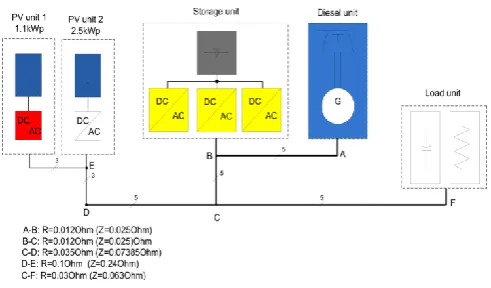
The present research work was jointly completed by ICCS-NTUA and CRES research infrastructures. In the former PHIL simulations were executed to emulate the behavior of a LV islanded power system including a diesel genset and inverter-based sources. Moreover, f-P and V-Q droops were incorporated into the respective inverters. The results were then verified at the real microgrid site in CRES premises. Fig. 1 illustrates the CRES microgrid infrastructure.
Figure 1. CRES microgrid topology.
The microgrid was setup and used either in single or in three-phase configuration according to the specific test. Unbalanced loading was also examined.
The DER units that were used for the tests include 3 battery inverters (13.5kWp), 1 diesel generator (12.5kVA), one load bank (13.5kW), 2 PV panels (1.1 and 2.5kW) and one three-phase capacitor. The operation and supervision of each unit is done using the local SCADA system, while for some measurements, portable equipment like current clamps and oscilloscopes were used. The fast transients and waveforms were measured by using oscilloscope.
The battery inverters used in the experimental tests are the SMA-Sunny Island 4500 inverters. By default, one of the inverters is connected to the appropriate grid phase and can operate in all possible modes such as grid-forming and grid-connected with droop characteristics. The other two inverters were reconfigured appropriately so that they operate under different modes.
The loads used in the experimental tests are 3 groups of resistors (2.5, 1.5 and 0.5kW), which are combined appropriately in order to obtain the maximum number of combinations.
2.1. Diesel Generator Droop Characteristics
and Tests
The diesel unit´s droop for the microgrid experiments is considered arbitrarily as -0.06Hz/kW according to its governor’s settings. Moreover, it is defined by (1) where Δf is the absolute change in the frequency (Hz) and ΔP is the absolute difference in the output power (kW) that caused the subsequent change in the frequency.
P f R=
Δ Δ
(1)
T
he diesel generator is studied in islanded mode under load variations where an increase in load demand imposes an increase in diesel power output and a subsequent reduction in torque frequency.frequency at the output of the diesel genset. Thus, its f-P droop curve was experimentally derived under symmetric and asymmetric loads.
2.2. Battery Inverter Characteristics and
Tests
The f-P and V-Q droops of the SI inverter [15] are given by (2) and (3) respectively where the parameters are set to: i) Δf pu=-2%, ii) ΔVpu=-6%. Moreover, these droop
curves were utilized for the RSCAD simulations.
) 50 ( 3 . 3 3
. 3
1
50 P P f
f=
(2)
) 230 ( 239 . 0 1818
. 4
230 Q Q V
V= (3)
The frequency droop curve was experimentally derived. In order to obtain each inverter's droop curve, data sets consisting of inverter's output frequency and active power have to be available. Not only the f-P droop calculation was evaluated but also the frequency, active and reactive power responses with static load changes.
3. Real-Time Simulations & PHIL Set-Up
Fig. 2 depicts the PHIL topology as implemented in NTUA research infrastructure.
In order to demonstrate the actual test with the PHIL setup, a series of preliminary actions had had to be pursued. The first simulation task was implemented on a three phase LV distribution network with and without the integration of the battery inverter. Subsequently, the system´s frequency was checked upon load changes with and without the storage penetration. In order to verify the frequency and power responses at the diesel generator´s terminals, a change of 105.8 Ohm was implemented in the resistive load at each phase with the utilization of a breaker.
The Power Hardware in the Loop experiments involved the following steps:
The protection modules were added into the RSCAD/RTDS simulated model to ensure the safe operation of the RTDS during the PHIL tests
The physical setup was verified
The power amplifier was tested and the simulation was executed in open loop
The loop was closed and the experiments were performed
Figure 2. PHIL environment in NTUA Lab for DER devices.
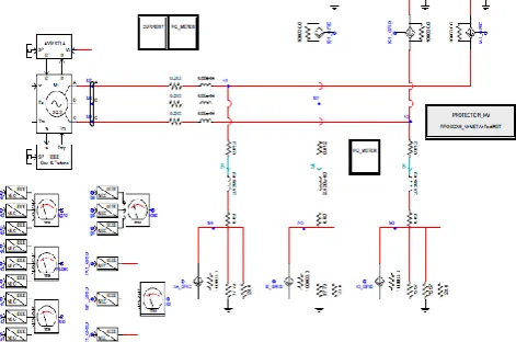
Fig. 3 shows the power system model during the PHIL test. The network topology includes a diesel generator, 2 LV lines, a bank of restive loads and a three-phase inverter.
Figure 3. RSCAD/RTDS model during the PHIL test.
Table 1, 2 and 3 summarize the network parameter values and the diesel generator internal characteristics necessary for the execution of the real time simulations. The diesel unit’s droop is considered as -6% (in percentage rates) for the RSCAD simulations.
Table 1. System parameters
Network Parameters Values
Vg_rms ph-ph 400 V
RLline1 0.012+j6.88E-4 Ohm
RLline2 0.042+j2.428E-4 Ohm
Diesel genset 13.164 kVA Battery Snom 3.3 kVA
Rload 12.6 kW
RHuT 105.8 Ohm
Ratings
3-phase Output Sn 13.164 kVA Voltage Un 230.94 V Current In 19 A Frequency f 50 Hz
Speed n 1500 rpm Pair poles p 4 Inertia Constant H 1.7 MWs/MVA
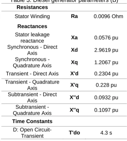
Table 3. Diesel generator parameters (B)
Resistances
Stator Winding Ra 0.0096 Ohm
Reactances
Stator leakage
reactance Xa 0.0576 pu Synchronous - Direct
Axis Xd 2.9619 pu Synchronous -
Quadrature Axis Xq 1.2067 pu Transient - Direct Axis X'd 0.2304 pu Transient - Quadrature
Axis X'q 0.228 pu Subtransient - Direct
Axis X''d 0.0932 pu Subtransient -
Quadrature Axis X''q 0.1097 pu
Time Constants
D: Open
Circuit-Transient T'do 4.3 s
3.1. PHIL Interface Concerns
Power Hardware–in-the-Loop technique employs as hardware part a device that generates or absorbs power, such as a PV inverter or an induction motor. Here, the presence of a power interface is necessary since it exchanges low voltage signals with the simulated system and real power with the HuT, thus the digital to analogue and vice versa converters cannot participate sufficiently in this trade-off .
The power interface being used throughout this paper for the experimental procedure consisted of a single phase (5KVA) AC/DC/AC converter and enables the low power output signal (i.e. IHuT_low and reference voltage labeled as
VN*) of the RTDS to be amplified to a higher voltage
signal (i.e. VN). This voltage is applied to the HuT device
(in our case an actual load) and provokes a current flow through it. The current waveform is measured by the power interface’s sensor and is fed back to the RTDS to close the loop (Fig. 4).
PHIL technique is a novel approach and offers great flexibility in arranging and performing various test scenarios for DER devices since the virtually simulated system can be modified without hardware adaptions, in
addition to the fact that the tests can be repeated quickly and accomplished very close to realistic conditions.
However, PHIL simulations occupy a closed-loop interaction. Shortcomings that inherently lie in this closed-loop can reduce the accuracy of the simulation and may evoke instability. These imperfections in the closed-loop topology are mainly produced by the Power Interface, such as the time delay and the low pass filter of the amplifier, the time delay of the sensor and the sensor’s noise [4]. Moreover, a time-delay is introduced by the RTDS.
3.1.1. Power Amplifier
The basic components of a power interface are the power amplifier and a sensor. The former amplifies the low level signals received from the RTS to the HuT at higher power ratings, thus high accuracy and small-time delay are key considerations.
The power amplifier used for this contribution is an unconventional single-phase bidirectional AC/DC/AC converter consisting of 3 IGBT half-bridges [4]. The converter is coupled to the utility grid on the one-side and runs as a voltage source of variable voltage and frequency on the other-side. Additionally, the analogue signals exchanging with the utility grid and the microgrid components is done on a conversion time of about 40μsec, 16 bit resolution and ± 10V range.
Figure 4. Representation of the PHIL environment.
The power electronic converter platform permits the user to model the control scheme in Matlab/Simulink, with access to the available measurements and the possibility to change some control parameters online. In this case, the control algorithm of the given converter was provided by the manufacturer and it was modified in order to fulfill the two basic functions which a power interface needs to provide with during a PHIL simulation, i.e. voltage amplification and supplying current feedback signal [4].
from the introduced time delay and the output filter of the power converter [4].
2 ) 1500 ( 2100 2
2 ) 1500 (
2 2
2
2 )
(
s s
n s n s
n =
s f T
(4)
n
ω , the resonance angular frequency.
ξ, the damping ratio.
The total time delay in the current PHIL experiments was about 750µsec.
3.1.2. Stability and Accuracy Considerations
Before performing a PHIL test, it is crucial to ensure that the experiment will be stable. Consequently, throughout this research work virtual hardware-in-the-loop experiments (off-line simulations) were performed in Matlab/Simulink to check the system’s stability for the different test scenarios presented in the following section. Furthermore, stability should be accompanied by an adequate accuracy of the experiments’ outcomes. Therefore, the entire closed loop system was simulated, and the results were compared with the outputs from the PHIL tests in order to assess their accuracy.
Apart from the comparison of the PHIL results with the corresponding outcomes from the off-line simulations, the validity of monitored quantities (current and voltage rms values) was also obtained through comparison of several measurements at different points in the system. For instance, the current through the hardware impedance (105.8 Ohm) was monitored by measurements of the Power Interface, an oscilloscope, and the software of the RTDS.
3.1.3. Protection Issues
Over-current and over-voltage protection schemes are introduced into the RTDS/RSCAD at the shared node between the simulation and hardware. Fig. 5 beneath illustrates the protections implemented for the execution of the PHIL experiments conducted for this research work.
In case the pre-determined limits are exceeded, IHuT
becomes zero and the voltage reference sent to the amplifier is held constant to a specific value. Subsequently, the output of the RTDS will be maintained constant and the PHIL test will be terminated. Flip-flops are employed to ensure the safe operation of the system if an instability incident takes place.
Figure 5. Protection design implemented in RTDS/RSCAD.
4. Results and Discussion
4.1. Experimental Results
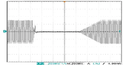
The diesel generator suffers from frequency and voltage fluctuations due to harmonics distortion in the pulsating torque. Fig. 6 depicts the frequency oscillation upon an indicative step change from 6 to 12 kW and 12 to 0 kW respectively in load demand. In transducer’s scale, 1V corresponds to Hz and 5V to 50 Hz.
Evidently, the diesel generator suffers from inherent frequency and voltage flickering. Moreover, the diesel f-P droop curve was experimentally derived under asymmetric and symmetric loads. The following captures (Fig. 7&8) illustrate these results respectively.
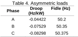
It is worth mentioning that under asymmetric loading the droop and idle frequency (fidle) differs from phase to phase where the biggest difference is detected on phase A. Table 4 summarizes this deviation in values. However, for a three-phase symmetric load the droop characteristic was confirmed at -0.06Hz/kW (Fig. 8).
Table 4. Asymmetric loads
Phase Droop
(Hz/kW)
Fidle (Hz)
Figure 6. Diesel’s frequency response under load stp change 612 kW and 120 kW.
Figure 7. The measured f-P droop curve of the diesel genset for asymmetric loads.
Figure 8. The measured f-P droop curve of the diesel genset for 3-phase symmetric loading.
It is hypothesized that this deviation is due to possible errors in data logging of the diesel genset´s droop and idle frequency potentiometers resulting in a slight change in the governor´s gains. This change can be attributed to environmental conditions, and especially temperature due to heat at the test site that can affect the results of the experiments.
The following figures (Fig. 9-11) illustrate the exerimental results from the battery inverters’ tests. In order to obtain each inverter's droop curve, data sets consisting of inverter's output frequency and active power have to be available. In more details, the f-P droop calculation was evaluated with static load changes and only one inverter being in use. The Sunny Boy PV inverter is also included. Moreover, the f-P droop was measured for operation of the three inverters (master-slave) with static load variation and asymmetries.
Figure 9. The f-P droop curve of one battery inverter (phase A).
Figure 10. The f-P droop calculation for three-phase operation.
In general, the Master Inverter defines the frequency in both cases: Either when it is connected to one phase or when the three inverters are connected to the three phases Slope: -0.08298
Slope: -0.04422
Slope: -0.07529
Slope: -0.0594
Slope: -0.29435
(master-slave operation); i.e. at 4.1 kW (single-phase) and 12.3 kW (three-phase) load demand, the frequency is the same at the figure of 48.6 Hz. In addition, under asymmetric loads any variation in the master inverter´s power output will once again define the change in the frequency. For instance, in our case the master inverter is connected to phase A, thus any changes in load demand at this phase and only in this phase will dominantly affect the frequency behavior. This result is evident in Fig. 11.
Figure 11. The f-P droop curve for asymmetric load variation with phase A (master inverter) and phases B, C (slave inverters).
Fig. 12 shows the f-P droop curve for the three inverters with a 2-hr load profile.
Figure 12. The battery inverters´ f-P droop curve for a 2-hr load profile.
One additional experiment included the investigation of the frequency and voltage behavior of the battery inverter by changing the load demand and switching the mode operation (grid connected to islanded transition). Fig. 13-15 depict these outcomes. First of all, in Fig. 13 only the master inverter is connected to phase A while the microgrid is islanded. The frequency and voltage fluctuations are derived from no-load to full load step change, i.e. 0 kW -4.1 kW.
Regarding the disconnection tests, the inverter´s voltage waveform does not change (Fig. 14) because the load is purely restive and not reactive, whereas its frequency suffers from a drop of 1.22 Hz, namely from 49.84 Hz to 48.62 Hz.
Figure 13. Battery inverter´s voltage and frequency response under step-change in the load.
Figure 14. Master inverter´s voltage disturbance (DroopMains mode).
Figure 15. Master inverter´s voltage disturbance (Fast Mains mode).
In Fast Mains operation the voltage falls to zero as it was expected when switching from grid connected to disconnected operation and the Sunny Island is behaved as grid former. Contradictorily, in DroopMains operation the voltage is undisturbed and the frequency falls to 49.6 Hz.
cases, the output power is measured: a) different droops (-2Hz/Pnom, -1Hz/Pnom) and fiddle (intersection of the droop f curve with the f axis) is of 50 Hz, b) same droop 1Hz/Pnom) and fidle=50 Hz and c) same droop (-1Hz/Pnom) but the idle frequency is changed to 50.3 Hz. Figure 16 illustrates these results respectively.
Figure 16. Load sharing for parallel operation of two Inverters.
4.2. Real-Time Simulations
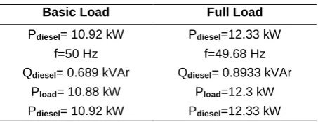
Tables 5 and 6 summarize the real time simulation results without and with the storage inclusion respectively. As it can be easily seen from the frequency figures beneath, the battery inverter presence enhances the frequency stability by covering part of the load change.
Table 5. Numerical results without storage
Basic Load Full Load
Pdiesel= 10.92 kW Pdiesel=12.33 kW
f=50 Hz f=49.68 Hz
Qdiesel= 0.689 kVAr Qdiesel= 0.8933 kVAr
Pload= 10.88 kW Pload=12.3 kW
Pdiesel= 10.92 kW Pdiesel=12.33 kW
Table 6. Numerical results with storage
Basic Load Full Load
Pdiesel= 10.93 kW Pdiesel=11.74 kW
f=50 Hz f=49.81 Hz
Qdiesel= 0.6898 kVAr Qdiesel= 0.8601kVAr
Pinv= -0.05 kW Pinv= 0.6173 kW
Qinv= 0.3035 kVAr Qinv= 0.374 kVAr
Fig. 17 & 18 show the RSCAD/RTDS numerically transient responses with and without the battery inverter penetration respectively.
From (1) and considering that the diesel active power output is rated at Pdiesel= 10.92 kW, the diesel droop characteristic is given by (5) beneath. Moreover, it is confirmed at 6%.
3 ) 50 ( 164 . 13 92 .
10 f
= diesel
P (5)
Figure 17. Frequency response (load change) without & with storage.
Figure 18. Diesel´s active power output with & without the battery inverter (load change).
-2 Hz/Pnom
-1 Hz/Pnom
-1 Hz/Pnom
4.3. PHIL Operation Outcomes
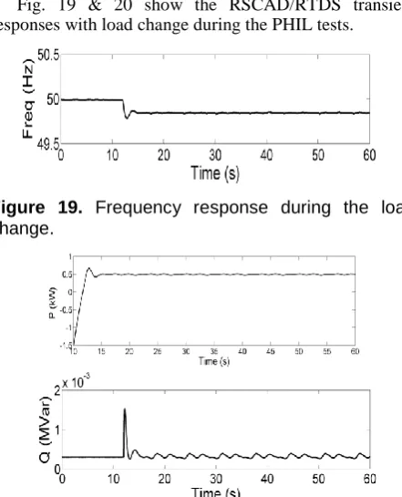
Fig. 19 & 20 show the RSCAD/RTDS transient responses with load change during the PHIL tests.
Figure 19. Frequency response during the load change.
Figure 20. Battery Inverter active and reactive power responses.
Acknowledgements.
This work is co-funded by the European Commission within the Seventh Framework Programme (FP7/2007-2013) DERri under grant agreement no 228449.
5. Conclusions
PHIL experiments render high flexibility in the research of the complex problems which concern the penetration of various energy systems with respect to network stability and security.
This study demonstrated an implementation of a microgrid model in real-time simulation platform for DER device integration. PHIL simulations were executed to emulate the energy management of a real microgrid system including a diesel synchronous machine and inverter-based sources.
Moreover, their dynamic behaviour was examined within the LV islanded power system and more than that the adequate performance of the laboratory set-up is verified through tests on a real experimental site.
Concluding, RSCAD/RTDS is an effective tool suitable for transient analysis due to its fast computation in real time and the laboratory hardware interfacing capability it offers. Additionally, at a later time, it is planned to extend the model in RSCAD/RTDS by including more simulations and experiments such as to examine the load sharing for parallel operation of two battery inverters being both connected in one phase and demonstrate the concept of the battery inverters' active power control by changing the frequency droop curve.
References
[1] P. Kotsampopoulos, A. Kapetanaki, G. Messinis, V. Kleftakis, N. Hatziargyriou, “A PHIL facility for microgrids”, International Journal of Distributed Energy Resources, vol. 9, no. 1, pp. 71-86, January-March 2013. [2] P. Crolla, A.J. Roscoe, A.Dysko and G.M. Burt,
“Methodology for testing loss of mains detection algorithms for microgrids and distributed generation using real-time power hardware-in-the-loop based technique”, The 8th International Conference on the Power Electronics-ECCE Asia, May 30-June 3, 2011, Korea.
[3] P. Kotsampopoulos, V. Kleftakis, G. Messinis, N. Hatziargyriou, “Design, development and operation of a PHIL environment for distributed energy resources”, The 38th Annual Conference of the IEEE Industrial Electronics Society IECON 2012.
[4] F. Lehfuss, G. Lauss, P. Kotsampopoulos, N. Hatziargyriou, P. Crolla and A.Roscoe., “Comparison of multiple power amplification types for Power Hardware-in-the-Loop applications”, IEEE Workshop on Complexity in Engineering (COMPENG 2012), June 11-13 2012, Aachen, Germany.
[5] A. Roscoe, A. Mackay, G. Burt and J. McDonald, “Architecture of a network-in-the-loop environment for characterizing AC power- system behavior”, IEEE Trans. Industrial Electronics, vol. 57, no 4, pp. 1245-1253, 2010. [6] RTDS Technologies: http://www.rtds.com
[7] M. Steurer, F. Bogdan, W. Ren, M. Sloderbeck, S . Woodruff, “Controller and power hardware-in-loop methods for accelerating renewable energy integration”, Power Engineering Society General Meeting, IEEE , vol., no., pp.1-4, June 24-28 , 2007.
[8] V. Karapanos, S. de Haan, K. Zwetsloot, “Real Time Simulation of a Power System with VSG Hardware in the Loop”, Proc. IEEE Industrial Electronics Society IECON’2011, Australia, November 2011.
[9] M. Dargahi, A. Ghosh, G. Ledwich and F. Zare, “Studies in power hardware in the loop (PHIL) simulation using real-time digital simulator (RTDS)”, IEEE International Conference on Power Electronics, Drives and Energy Systems, December 16-19, 2012.
[10] P. McLaren, R. Kuffel, R. Wierckx, J. Giesbrecht and L.Arendt, “A real-time digital simulator for testing relays”, Power Delivery, IEEE Trans. on, vol. 7, pp. 207-2013, 1992.
[11] A. Sattar, A. Al-Durra and S. Muyeen, “Real time implementation of STATCOM to analyze transient and dynamic characteristics of wind farm”, 37th
Annual Conference on IEEE Industrial Electronics Society, pp. 3742-3747, IECON 2011.
[12] G. Lauss, F. Lehfuss, A. Viehweider, and T. Strasser, “Power Hardware in the Loop Simulation with Feedback Current Filtering for Electric Systems,” 37th Annual Conference of the IEEE Industrial Electronics Society (IECON’2011), November 7-10, Australia, 2011.
[13] H. Li, M. Steurer , K.L. Shi , S. Woodruff, and D. Zhang,“Development of a Unified Design, Test, and Research Platform for Wind Energy Systems based on Hardware-In-the-Loop Real Time Simulation”, IEEE Transactions on Industrial Electronics, Volume 53, Issue 4, June 2006 Page(s):1144 – 1151.
[14] O. Vodyakho, C.S Edrington, M. Steurer, S. Azongha, and F. Fleming,“Synchronization of three-phase converters and virtual microgrid implementation utilizing the Power-Hardware-in-the-Loop concept”, 25th IEEE Applied Power Electronics Conference and Exposition (APEC), 2010. Sunny Island 4500 manual