Optimization of Engine Cover
Shrikant Ghatiga1, Dr.S.N Kurbet2
1
PG students,Basaveshwar Engineering College, Bagalkot,Karnataka,India
2
HOD, Mechanical Department, Basaveshwar Engineering College, Bagalkot,Karnataka,India
Abstract —The speed of the car depends on the air flow on the outer surface of car. More the front surface area of car exposed to the air fluid more the drag created on the car and hence it lowers the speed of the car which directly affects the car efficiency. The front portion of car has to be designed based fluid dynamic loads as well as structural loads. The current scope of the work is study the structural stability of bonnet for the misuse analysis. These misuse analysis loads (structural) occur while opening or closing of bonnet during the service of car engine. The scopes also focus on the reduction of mass of the bonnet structure and check for the strength to weight ratio factor without compromising the factor of safety. . The weight of car bonnet can affect the efficiency of overall performance of vehicle, so that here adopting the technique like topometry, topology, size and topography to optimize the existing one. The final result shall have reduced weight of bonnet.
Keywords — Optimization, Analysing, Engine Cover
I. INTRODUCTION
In present days the automobile industries growing towards green approach which means less environmental effect or impact. To achieve reduction in consumption of fuel mainly the paper focuses on the weight loss of vehicle. This benefits the utilization of less raw material and production of part with utilization of less energy.
Engine cover not only plays important role in air guiding, it also plays a role in the protection of engine and pipeline accessories. In design point of view, the front cover has stiffness which is equal to the actual requirement of stiffness with lightest quality.
Engine cover purpose
The engine cover or bonnet is a system which is an entrance penal to the engine compartment to provide maintenance of battery, power train, belt drives, lamp units and fluid levels. It is basically reinforced because of many safety and quality requirement.
Process of optimization: There are many different optimization processes provided by the “Altair engineering software” are using progressively. The
optimization process include topometry, topography and size optimization.
1. Topology: It is one of the techniques which assign value of density to each element. The density value within the range 0 to 1, for every load step the density value shows their importance of element. Where 1 indicate the fundamental element, and 0 indicate elimination of element without lowering the performance of entire structure. The result of this technique thereafter reinterpreted with 3D CAD model of bonnet substructure.
Topometry: It is technique of optimization, by this technique the thickness distribution to 2D element, which spread across the entire structure. This technique show or indicate the strengthening part and also
shows the collapsing or eliminating
part for lightening the whole structure.
Topography: It used to optimize the shape with defined region part. Using optistruct the pattern can generated for reinforcement. This technique allows us to see the deformation of ribs or which acting like a reinforcement. Size, in this here optimize the properties of an element like shell thickness and other like cross-sectional property, mass, beam, has modified to solve problem regarding optimization.
2. LITERATURE SURVEY
Here the researcher had been studying that different material for the bonnet. Researcher also studied that how to optimize the bonnet. How to lower the weight and which technique they adopted to solve problem. Here are some of the paper which have portrayed.
analysis of five different material and result of these material is compared with various parameter actual material and drawed the result based on this. Finally he concluded analysis 5 different material has compared at a time to actual material and result of glass reinforced polypropylene material has less deformed when it compared to existing one and analysed the critical area by fatigue life analysis. Yu Xiang, Jiatong Li, Zhaozhao.Tian.[2] Here they said that hood part of car which plays a very important role in effecting the performance. He taking the hood as an example, importing the 3D model of hood from the catia to hypermesh, constrained mode , several condition of stiffness is solved or calculated by the optistruct. By size optimization using sensitivity analysis, they have made the objective that minimum mass of hood. He made every component thickness is optimized with meeting the required stiffness therefore whole vehicle performance can be improved.
D. costi, E.Torricelli, L.Splendi and M. Pettazzoni.[3] In this, the automobile industries facing a lot of problem regarding environment to compensate this problem is green approach. That is changing the fuels, we can meet the objective as light weight. In this method technique are used to optimize the automobile substructure hood. That is the technique are topology, topometry, topography used to optimize without disturbing the performance and the mass also reduced.
3. METHODOLOGY
Geometry creation: The decklid or bonnet geometry reference file taken from the previous car program. The reference geometry file is imported in the catia CAD software and modified the geometry to meet the current car programing dimensions, the edited decklid geometry is exported as a dot IGES file.
Decklid or bonnet discretization: The dot IGES file is taken in to the preprocessing tool called a hypermesh. While importing the dot IGES file the scaling factor is adjusted with approximate unit conversion constant(1inch=25.4mm). The geometry clean up process is carried out on the bonnet geometry file to remove unwanted geometry feature such as chamfer, small holes, duplicate surfacess and non manifold edges. After completing the clean up the meshing is carried out using meshing commands like automesh, drag, line drag, ruled and spin on the curved surfaces automesh command is effectively used to capture the curvature and at bolt locations a washer has to be mentained with a even number of quard element so as to distribute stress uniformly in radial direction. To mesh a washer spin command is
used and rest of the remaining surfaces we can use either of the above mesh command.
Material and section properties assignment: Once the mesh is completed the appropriate material properties of a steel with a density is equal to 7.85e^-9 ton/mm^3, poisson’s ratio of 0.3 and youngs modulus of E= 210Gpa.Since the geometry is meshed with plane membrane elements the shell section properties are assigned to all the meshed component.
Element quality check: All the element are checked for the following quality parameter.
a) Warpage of a 15 degree. b) Aspect ratio 5.
c) Skew of 60 degree. d) Minimum length for 2mm. e) Maximum length for 14mm. f) Jocobian of 0.5.
After the element quality checks. The model is checked for the continuity and compatibility condition by finding the free edges.
FE model connections: RBE2 element are used at bolt locations which are interned connected to bar elements(shank of bolt)
Loads and boundary conditions: The bonnet is fixed at the hinged point in all six degree of freedom and external load is applied at the mid of the extreme portion of bonnet.
Fig.1 FE model of Bonnet
In hypermesh the boundary condition is called as load collecter. The above figure red circle which is situated towards wind screen indicating that they are fixed in xyz translation and xz rotation. The rotation about y is zero. The red circle which situated toward
bumper is fixed in z translation.
to execute and solve the FE model of the decklid. After solving the result file is generated as a dot ODB file (Out put data base). Dot ODB file is binary file which is imported in to a abacus viewer to post process the results.
Post processing of the results: The stress-strain and deflection counterplotes are generated from the abacus viewer and discussed in section or chapter “result and discuss
4. RESULT AND DISCUSSION
Load case 1: Handle load in vertical downward direction (without removed material)
Fig 1.1
In the above figure 1.1 the maximum von mises stress is observed as 279MPa.
Maximum principle stress
Fig 1.2
In the above figure 1.2 the red spots are observed as maximum principle stress which is of 323Mpa.(Tensile)
Minimum principle stress Min principle stress is 323Mpa
Fig 1.3
In above figure 1.3 the blue colour spots is observed as minimum principle stress which is of 321MPa.(compressive)
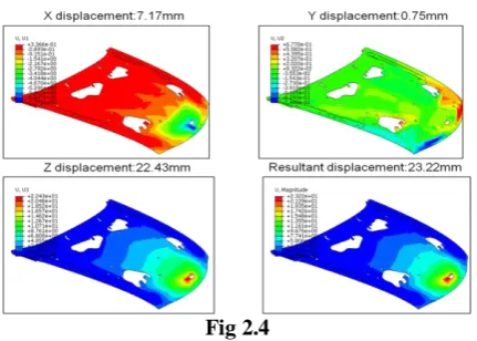
Displacement plot
Resultant displacement. 23.22mm Z displacement. 22.43mm
X displacement. 7.17mm Y displacement. 0.75mm
Fig 1.4
From above fig 1.4 here it is observed that magnitude of resultant displacement is 23.22mm.
Load case 2: Handle load in vertical Upward
direction (without removed material)
Von Mises stress Max von mises stress is 279MPa
Fig 2.1
Maximum principle stress
Max principle stress is 321MPa
Fig 2.2
Here it is observed from fig 2.2 is Maximum principle stress(tensile) is 321MPa.
Minimum principle stress
Minimum principle stress is 323MPa
Fig 2.3
Here it is observed from the Fig 2.3 that minimum principle stress is 323MPa.
Displacement plot
Fig 2.4
From above fig 2.4 here it is observed that magnitude of resultant displacement is 23.22mm.
Load case 3: Handle load in vertical Downward direction (unwanted material is removed)
Von Mises stress Max von mises stress is 279MPa
Fig 3.1
From above Fig 3.1 here it is observed that the von mises stress is 279MP
Maximum principle stress Max principle stress is 323MPa
Fig 3.2
Here it is observed from fig 3.2 is Maximum principle stress(tensile) is 323MPa.
Minimum principle stress
Minimum principle stress is 321MPa
Fig 3.3
Here it is observed from the Fig 3.3 that minimum principle stress is 321MPa
Fig 3.4
From above fig 3.4 here it is observed that magnitude of resultant displacement is 23.57mm.
Load case 4: Handle load in vertical Upward direction (unwanted material is removed)
Von Mises stress Max von mises stress is 279MPa
Fig 4.1
From above Fig 4.1 here it is observed that the von mises stress is 279MPa
Maximum principle stress
Max principle stress is 321MPa
Fig 4.2
Here it is observed from fig 4.2 is Maximum principle stress(tensile) is 321MPa.
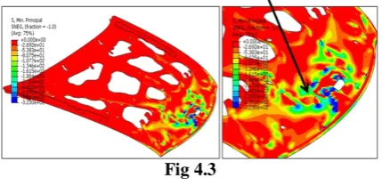
Minimum principle stress
Minimum principle stress is 323MPa
Fig 4.3
Here it is observed from the Fig 4.3 that minimum principle stress is 323MPa
Displacement plot
Fig 4.4
From above fig 4.4 here it is observed that magnitude of resultant displacement is 23.57mm.
Material properties
Steel with YS of 355 MPa is used.
Young’s modulus (MPa): 2.1
Density(tons/m ): 7.85E-9
Poison’s ratio:0.3
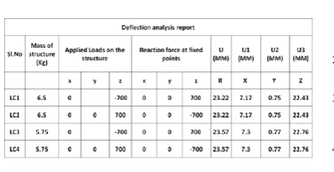
Table 5.2 Result summary
5. CONCLUSION AND FUTURE SCOPE
Conclusion
From the above result summary chart, the maximum stress observed is 323MPa and is well below the yield strength, of 430MPa hence the structure is safe and has a factor of safety 1.3. The following observation are made and compared as below.
1. The stress in the all four load cases are almost equal around 323MPa, hence the removal of material has not influenced the stress distribution. So strength wise the structure is safe.
2. The removal of material in load case three and four has influenced the deflection patterns and hence the deflection increasing with removal of material.
3. From the above abservation it is evident that removal of material as reduced the weight of structure by 0.75kg without change in strength hence strength to weight ratio is achieved and factor of safety is 1.3
So from the above conclusion the structure is safe and can be recommended for manufacturing.
Future scope
From the conclusion report it is evident that the stresses are well below the yield strength and there are slight difference with respect to deflections of the hood structure. This change in deflection is due to mass reduction or material removal from the low concentration stress region. Hence still there is scope to remove the material from the low concentration stress region and do the design of experiments to optimize the hood structure with respect to strength to weight ratio.
6. REFERENCES
1) YuXin Wanga, QingChun Wangb, JianRong Fuc, HongHai Qiaod [2012]; “Optimization of the Engine Hood to reduce the Head Injury during the Vehicle-Human Collision”
2) Harish Mugutkar, D Swetha [2015]; “Static and modal analysis of engine cover for different materials”
3) Hongyang Qiu , Yajuan Huanga, Qiang Liu [2007];“The study of engine hood panel forming based on numerical simulation technology”
4) Yu Xiang, Jiatong Li, Zhaozhao Tian [2014]; “The Finite Element Analysis and Optimization of the Hood Based on Hyperworks ”
5) Rupesh Y. Bhagat and Amol P. More [2014]; “A Review: Analysis and Optimization of Car Bonnet”
6) D. Costi, E. Torricelli, L. Splendi and M. Pettazzoni [2011];
“Optimization Methodology for an Automotive Hood Substructure (Inner Panel)”
7) Zhang, Xinyi; Wang, Chengyong; Wang, Siyan ; Cheng, Yongzhang; Guo, Fangfang. Duanya Jishu - Forging &Stamping Technology 40.10 (October 25, 2015): 49-54. “Optimization of wavy contour of the stamping blank for engine cover based on reverse reckoning”
8) Sen Zhao1,a, Xiaohui Cao1,b [2012]; “Finite Element Analysis and Optimization of S1110 Diesel Engine Body”
9) Zhang, Huan-Yu; Hao, Zhi-Yong. Journal of Zhejiang University. Engineering Science 47.2 (Feb 2013): 261-266.
“Influence of flywheel cover structural stiffness on engine body NVH performance”
10) Yu Xiang1, a, Jiatong Li1, b, Zhaozhao Tian2, c [2014];