64 |
P a g e
DESIGN AND DEVELOPMENT OF DATA RECOVERY
SYSTEM FOR FADED WIRELESS COMMUNICATION
CHANNEL
S. Venkateswarlu
1, Ms. Ch. Radhika Rani
2, Ms. SNM Sitara
31,2
Research Scholar, Department of ECE, KL University,
Vaddeswaram, 522 502, A.P., (India)
3
B. Tech (Third Year, ECE) Student, KL University,
Vaddeswaram, 522502, A.P.,( India)
ABSTRACT
Wireless communication channel is being used as primary means of communication nowadays. Data is DPSK modulated and hamming encoded before being given as input to the Rayleigh Faded Wireless Communication channel. This paper mainly focuses on the data re-generation techniques from phase modulated data at the source side. The generated data is made to pass through the channel by undergoing various transmission impairments. To accurately regenerate the data at the receiver side equalizers are recommended for usage. Decision feedback equalizer is one such equalizer that reproduces the data accurately. It takes care of all types of the noise components and suppresses the AWGN also. It counters the Doppler Effect and ISI most accurately.
Keywords: Feedback Equalizer, Doppler correction, I channel and Q channel.
I DATA GENERATION
The input to the system is the message of 'L' number of characters. The model converts the given text into ASCII
code and supplies the bit stream to DPSK encoder[3].
The general representation for a set of M-ary phase signaling waveform is[6][3]
S(t) = {U(t) exp j ( 2Πfc t + 2Π (m-1) / M + θ )}
0 ≤ t ≤ T,
m = 1,2,3,4
θ = initial phase.
Where U(t) is a rectangular pulse with amplitude 'A'
S(t) = A cos [2Πfc t + 2Π (m-1) / M + θ]
= AChannel Simulation cos [2Πfc t ] – Aem sin[2Πfc t]
Where AChannel Simulation = cos [2Π (m-1) / M + θ ]
Aem = sin [2Π (m-1) / M + θ ]
65 |
P a g e
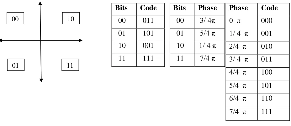
The mapping or assignment of information bits to the M possible phases more commonly done using the logicdescribed here under as shown in Fig (1).
In a four phase PSK, sets of two successive bits are mapped on to the four possible phases. When a pair of bits is
encoded, say 0 1, the phase corresponding to this combination i.e., 5Π/4, added to the phase shift corresponding to
the previous bit interval, say 7Π/4, to give the phase shift the present interval[6].
Thus while in the previous bit interval a sinusoid of signaling frequency fc with phase shift 7Π/4 was transmitted, in
the present interval the sinusoid is transmitted with a phase shift of 7Π/4 + 5Π/4 = Π.
Fig (1) Signal Constellation for 4 ary PSK
When θ > 0 is used, the signaling phase is shifted in every signaling interval, even when a long string of zeroes
occur in the information. This results in a signal spectrum with a width that approximately equal to 1/T. (T is the
signaling interval). The spectral components above and below the carrier are used in maintaining synchronization at
the receiver. Hence their presence in the received signal is important. Thus a non zero value of 'θ' (θ = π/4) is used in
such a case. With equal to four and θ equal to π /4, eight possible phase shifts exist.
The sequence of pulses {∑k ak } or ∑i Si ( t – iT ) from DPSK is fed to the radio equipment transmitter filter „G‟. It
has an impulse response of g(t) and a transfer function of G(f). The output this filter is real-valued and is given by
S(t) = R [ ∑i Si ( t – iT ) ] * g(t) (* represents Convolution)
= ∑i Si ( t – iT ) * g(t) + ∑i Si* ( t – iT ) * g(t)
= ∑i Si g ( t – iT ) + ∑i Si* g ( t – iT )
II DATA TRANSMISSION
When S(t) is fed into a single Rayleigh fading HF channel the output would be [3][7][4]
-x(t) = S‟(t)q1(t) + S^(t)q2(t)
where q1 (t) and q2 (t) are random process.
Bits
Code
00
011
01
101
10
001
11
111
Bits
Phase
00
3/ 4π
01
5/4 π
10
1/ 4 π
11
7/4 π
Phase
Code
0 π
000
1/ 4 π
001
2/4 π
010
3/ 4 π
011
4/4 π
100
5/4 π
101
6/4 π
110
7/4 π
111
00
10
66 |
P a g e
The random processes have been generated by filtering the zero mean white Gaussian noise signal through a Beselfilter. The frequency and impulse response of Bessel filter approach Gaussian when the order of the filter is
sufficiently large. For the three sky waves, the model has, which requires six random processes q1(t) to q6(t). The
variance of all six variables is equal to 0.167. It ensures that the total variance of the three sky wave channel is unity.
Each of the values of qi(t) generated from an independent source so that they will be uncorrelated [4].
S^(t) = S‟(t) * f(t)
Where f(t) is the impulse response of a Hilbert Transform filter whose Fourier transform given by [5]
F(f) = j f < 0
= 0 f = 0
= -j f > 0
S^‟(T) = { ∑i Si g ( t – iT ) + ∑i Si* g ( t – iT ) } * f(t)
= ∑i Si (g ( t – iT ) * f(t)) + ∑i Si* (g ( t – iT ) * f(t))
Where Si *
is complex conjugate of Si
Let us consider that the modeled channel has three independent Rayleigh-fading sky waves. The relative delay of the
two sky waves from direct path be 'τ‟ seconds and 'τl' seconds respectively. The output from the channel is given by
[8]:
x(t) = [ S‟(t) q1 (t) + S^‟(t) q2(t) ] + [ S‟(t - τ) q3 (t) + S‟(t- τ) q4 (t) ]
+ [ S‟(t-τl) q5 (t) + S‟(t- τl) q6(t) ]
While passing through the channel, the signal is modified as a result of random noise n(t) added to it. The noisy
signal x'(t) is then passed through receiver filter C(t). The receiver filter output is given by
y(t)= x(t) * C(t) + n(t) * C(t)
The output of the matched filter d(t) is given to the demodulator where the signal splits into inphase ( I ) and
quadrature ( Q ) channels.
I channel input is given by
y'(t) = {[ x(t) * C(t) * d(t) ] exp (-j2Πfct)}
+ {[ n(t) * C(t) * d(t) ] exp (-j 2Πfc t)}
Where n(t) = noise produced at the output of receiver filter due to additive noise AWGN at the receiver input.
This can be written as
y'(t) = { μ∑I ai p(t-kT)n(t) } exp(-j2Πfct)
Where μ = Scaling factor,
p(t) = Defined pulse,
p(0) = 1,
μp(t)= x(t) * C(t) * d(t);
∞
y‟(ti ) = μai + μ ∑k ≠ i akp[(i-k)T] + n(ti)
k = -∞
67 |
P a g e
2 nd term = Residual effect of all other transmitted bits on the Ith bit,3 rd term = Noise sample at t.
The residual effect due to occurrence of pulses before and after the sampling instant ti called ISI. In the absence of
ISI and noise,
y(ti) = μ ai
III DATA RECOVERY
In the absence of noise, in the ith signaling interval, the received signal can be simply represented as [9]
Ri(t) = sin(2 Πfc t + θ + t )
Where fc = Carrier frequency having a phase shift of (θ + t )
t = Information bearing
θ = Unknown phase shift which represents the path delay and
relative phase difference between transmitter and receiver
oscillators.
Fig (2) Model of Data Receiving System over Radio Link
The in-phase (I) channel of demodulator gives
T2
Xc = ∫ Si (t) cos ( 2Πfc t) dt
T1
= ∫ 1/2 ( sin (4Πfct + θ + t ) + sin (θ + t)) dt
= l/2sin(θ + i )
Where T1 -T2 corresponds to a time period in which fc has an integral number of cycles.
68 |
P a g e
= 1 / 2 sin (θ + i-1)assuming path delay is constant for two Successive signaling intervals.
Similarly the quadrature phase (Q) channel of demodulator will give
T2
Yc = ∫ Si (t) sin ( 2Πfc t) dt
T1
= ∫1/2 (cos (θ + t) - cos (4Πfct + θ + t ) ) dt
= l/2cos(θ + i ))
Yp = Yi-1 = Yc in the previous signaling interval.
= 1/2 cos (θ + I-1 )
The final outputs of the system are R and Q signals.
R = X c * Xp + Yc * Yp
= k sin(θ + i ) sin (θ + i-1 )
+ k cos (θ + i ) cos (θ + i-1 )
and
Q = Xc * Yp – Yc * Xp
= k sin(θ + i ) cos (θ + i-1 )
- k cos (θ + i) cos (θ + i-1 )
The decision is now made on the basis of the signs of 'R' and 'Q' signals as given under.
R < 0 & Q < 0 01 ; R < 0 & Q > 0 00 ;
R > 0 & Q < 0 11 ; R > 0 & Q > 0 10 ;
The period of integration T2 – T1 makes it possible to avoid the use of band-pass filter separate out noise (if any)
from received signal.
During data demodulation, the carrier fc generated at receiver should not run freely. It must be locked to a fixed
phase at the beginning of every signaling interval. This is necessary to avoid a differential phase shift in the locally
generated carrier, multiplying the incoming phase in successive signaling intervals. This differential phase shift
would other wise add to the information bearing phase shift (i - i-1) and cause erroneous decisions to be taken at
the demodulator.
REFERENCES
[1].
M. Patzold, U. Killat, and F. Laue, “A deterministic digital simulation model for Suzuki processes with application to a shadowed Rayleigh land mobile radio channel” IEEE Trans. Veh. Technol., vol. 45, pp.318-331, May 1996.
69 |
P a g e
[3].
S. Venkateswarlu, Sastry JKR, “Justification of Rayleigh faded channel for data transmission in wireless environment” IJETT journal, vol 14, No 4 August 2014, pp106-109[4].
S. Venkateswarlu, Dr LSS Reddy: “A Channel Model over a frequency selective Rayleigh Faded Channel forData Transmission” AOM/IAOM International conference at Virginia, US, 12th to 15th August 2005
[5].
http://www.lightwaveonline.com/articles/wdm/print/volume-4/issue-7/dpsk-offers-alternative-high150speed-signal-modulation-54922077.html
[6].
S. Venkateswarlu, Dr JKR Sastry, “A Qualitative analysis of Rayleigh Faded frequency selective channel simulator” paper published in International Journal of Applied Engineering Research, ISSN 0973-4562 Volume9, Number 22 (2014) pp. 10281-10286
[7].
E. F. Casas and C. Leung, “A simple digital fading simulator for mobile radio,” in Proc. IEEE VehicularTechnology Conf., Sept. 1988, pp.212–217.
[8].
T. Eyceoz, A. Duel-Hallen, and H. Hallen, “Deterministic channel modeling and long range prediction of fastfading mobile radio channels,” IEEE Commun. Lett., vol. 2, pp. 254–256, Sept. 1998.