290 | P a g e
DOUBLE BAND RECTANGULAR MICROSTRIP
PATCHANTENNA FOR VARIETY OF WIRELESS
CONNECTIVITY APPLICATIONS
K.Hymavathi
1, R.Srihari
2, M.Nagaraju
3 1. Associate professor, Department of ECE, SRTIST, Nalgonda (India)
2
Associate professor, Department of ECE, SRTIST, Nalgonda (India)
3
. Assistant professor, Department of ECE, SRTIST, Nalgonda (India)
ABSTRACT
In this paper, a HFSS is used to design a Rectangular Microstrip Patch Antenna. The aim of this thesis is to
design and fabricate an Rectangular Microstrip Antenna and study the effect of antenna dimensions Length (L) ,
Width (W) and substrate parameters relative dielectric constant (εr) , substrate thickness on power,vswr, return loss, impedance, admittance parameters . Low dielectric constant substrates are generally preferred for
maximum radiation. Conducting patch can take any of the shape but rectangular and circular configurations
are the most commonly used configuration. The other configurations are more complex to analyze and require
heavy numerical computations.
The length of the antenna is nearly half wavelength in the dielectric; it is a very critical parameter, which
governs or control the resonant frequency of patch antenna. In the view of design, selection of patch width and
length are the major parameters along with feed line depth. The desired microstrip patch antenna design is
initially simulated by using HFSS simulator and patch antenna is realized as per design requirements.
Keywords: Compact, Rectangular, WLAN, HFSS, Coaxial Feed.
I. INTRODUCTION
Because of the booming demand in wireless communication system and UHF applications, microstrip patch
antennas have attracted much interest due to their low profile, light weight, ease of fabrication and compatibility
with printed circuits. However, they also have some drawbacks, such as narrow bandwidth, low gain spurious
feed radiation limited power handling capacity. To overcome their inherent limitation of narrow impedance,
bandwidth and low gain, many techniques have been proposed and investigated. When we change the shape of a
microstrip antenna and it is covered with a dielectric layer , its properties like resonance frequency, gain are
changed which may seriously degrade or upgrade the system performance. Therefore, in order to introduce
appropriate correctness in the design of the antenna, it is important to determine the effect of dielectric layer and
291 | P a g e
Structure of a Microstrip Patch Antenna
II. DESIGN OF MICROSTRIP PATCH ANTENNA
In this paper, the procedure for designing the rectangular micro strip patch antenna were explained. Next, a
compact rectangular micro strip patch antenna is designed or W L A N , Bluetooth & Wi-MAX. Finally, the
results obtained from the simulations will be demonstrated. Results show that the proposed antenna has
promising characteristics for Bluetooth and Wi-Max at 2.42 GHz frequency for Bluetooth & WLAN and 3.2
GHz for Wi-MAX application respectively.
The resonant frequency selected for my design is 2.44 GHz.
1. εreff is calculated as follows :
2. ΔL is calculated as below:
3.For the particular resonate frequency the effective length of the patch is calculated by:
4. Considering the rectangular patch Microstrip antenna the resonating frequency for the mode TMmn is given by
Where, m, n are the operating modes of the Microstrip patch antenna, along with L –length W- width.
5. For the effective radiation the design of the structure is the utmost important aspect and for this the width is
292 | P a g e
III. DESIGN CALCULATION
3.1 Dielectric Constant of the Substrate (εr)
The dielectric material of the Microstrip Patch Antenna is FR-4 with εr = 4.4, as this one of the maximum values of the dielectric substrate has been taken in order to reduce the size of the antenna.
3.2 The Frequency of the Operation (f0)
The frequency of operation for the Patch antenna design has been selected as 2.44GHz.
3.3Height of the Dielectric Substrate (h)
Microstrip Patch antenna has been designed in order to rule out the conventional antenna as the patch antennas
are used in most of the compact devices. Therefore the height of the antenna has been decided as 1.6mm.
3.3.1 Calculation of Width
By the formula
With the substituting the values of c=3x10⁸m/s fr = 2.44GHz and h = 1.6mm Width w = 0.03742m = 37.42mm.
3.3.2 Calculation of Effective Dielectric Constant
From the equation With the substituting the values εr = 4.4, h = 1.6mm, w=37.42mm Effective Dielectric Constantεreff = 4.0819
3.3.3 Calculation of Effective Length
From the equation
With the values εreff = 4.0819, c= 3x10⁸m/s fr = 2.44GHz.
3.3.4 Calculation of the Length Extension (ΔL)
293 | P a g e
With the values from h, w and εreffthe ΔLis being calculated as 0.7387mm ΔL= 0.7387mm.3.3.5 Calculation of Length of the Patch
By the equation
Where ΔL= 0.7387mm, Leff = 30.4277mm L =28.9503mm.
3.3.6
Calculation of Bandwidth
Β (εr
-1)wh/εr2LB
3.3.7
Calculation of Voltage Signal Wave Ratio
From the equation given below:
VSWR = (1+|Γ|)/(1-|Γ|) Γ
= reflection coefficient
Where, Γ =0.4
VSWR = 2.333
3.3.8 Calculation of the Return Loss for the Patch Antenna
From the equation given below:RL = -20log |Г| (dB)
Where, Γ =0.4
RL= 7.96 dB
3.3.9 Calculation of the Ground Plane Dimensions (
Lgand
Wg) of the Antenna
The transmission line model which is applicable to the infinite ground planes only. However, for a practical
considerations, it is essential that to have a finite ground plane. Hence, it has been shown by this similar results
for a finite and an infinite ground plane can be obtained if the size of a ground plane is greater than the patch
dimensions will be approximately six times from the substrate thickness which all around the periphery.
Therefore, for that design, the ground plane dimensions would be given from the equation is:
Lg = 6h + L
Wg = 6h + W
Where h= 1.6 , L=28.95mm ,W=37.42mm
Lg = 38.55mm
Wg = 47.02mm
294 | P a g e
IV. DETAILS OF THE SLOTS ON THE PATCH OF PROPOSED ANTENNA WILL BE
GIVEN AS
There are two rectangular slots of 12mm * 4mm at the coordinates on (-14.475,-15,1.6) and (14.475,15,1.6)
respectively.
The centre of the patch will be taken as the origin and the feed point location is given by the co-ordinates (Xf&
Yf) from the origin whose value which is given as (3.2 & 5) respectively. The feed point must be located at that
point on the patch, where the input impedance is 50 ohms for the specified resonant frequency. Therefore, a hit
and trial error method which is used to find the location of the feed point. For different locations of the feed
point coordinate Xf& Yf , the return loss (RL) is recorded and that feed point is selected as the optimum one
where the RL will be most negative i.e. less than or equal to -10 dB. Hence in this example, Xf& Yf are varied
in the specified range i.e. 1mm ≤ Xf≤ 5mm, 0mm ≤ Yf ≤ 10mm. So here the feed point coordinates must be
(3.2,-1.6,5) shown in Figure1.
V. RETURN LOSS
The center frequency is selected as the one at which the return loss is minimum. As described in chapter 4, the
bandwidth can be calculated from the return loss (RL) plot. The bandwidth of the antenna can be said to be
those range of frequencies over which the RL is greater than -9.5 dB (-9.5 dB corresponds to a VSWR of 2
which is an acceptable figure). Figure 2& Figure 3 shows the S11 parameters (return loss) for the proposed
antenna without slot and with slot respectively. From the Figure 2 it is to be clear that the designed antenna will
not resonates at the 2.42 GHz and 3.24 GHz frequencies. But after making the two rectangular slots in the patch
antenna of dimensions 12mm * 4mm the designed antenna resonates at the 2.42 GHz and 3.24 GHz frequencies
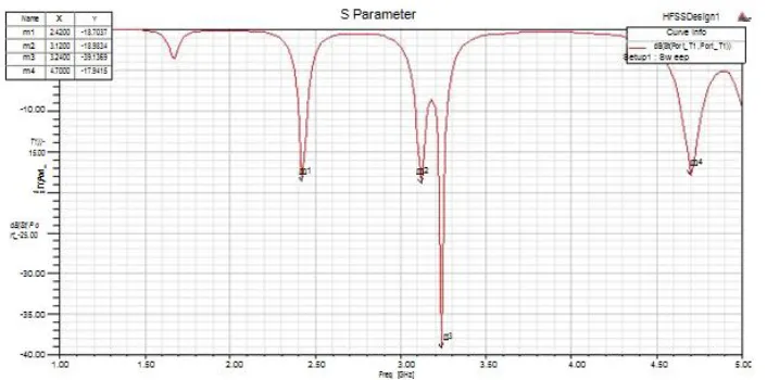
respectively. Figure 3 shows that the return loss for the 2.42 GHz is -18.7037 dB and the return loss for the 3.24
GHz is -39.1369 dB which covers the minimum required value of return loss of -10 dB.
295 | P a g e
Fig.3 Return Loss of Microstrip Patch Antenna with two rectangular slots
VI. VOLTAGE STANDING WAVE RATIO (VSWR) OF MICROSTRIP PATCH ANTENNA
Figure 4 and Figure 5 shows the plot of VSWR vs frequency of the simulated antenna without slot & with slots
respectively. In Figure 5 VSWR must lie in the range of 1-2 which has been achieved for 2.42 GHz and
3.24GHz frequency, near the operating frequency value. The VSWR ratio at 2.42 GHz frequency is 1:1.2627
and the VSWR ratio at 3.24 GHz frequency is 1:1.0223 is shown in Figure 5.
Fig.4 VSWR v/s Frequency Plot of without slot antenna
296 | P a g e
6.1 Radiation Pattern plots
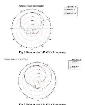
Since a Microstrip patch antenna radiates normal to its patch surface, the elevation pattern for = 0 and = 90 degrees would be important. The radiation pattern showing the gain for the desired slotted antenna has been
shown in Figure 6 &Figure 7.
Fig.6 Gain at the 2.42 GHz Frequency
Fig.7 Gain at the 3.24 GHz Frequency
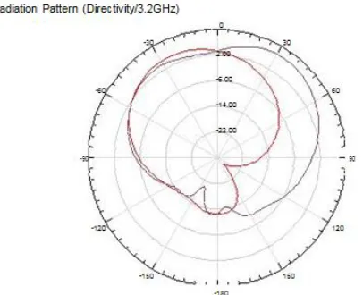
The radiation pattern showing the directivity for the designed slotted antenna has been shown in the Figure 8 &
Figure 9.
297 | P a g e
Fig.9 Directivity at the 3.24 GHz Frequency
VII. CONCLUSION
Microstrip antenna has numerous inherent advantages such as low profile, light weight, easy fabrication and
suitability of mass production compatibility with planar solid state devices. A Microstrip patch antenna is that
type of antenna which offers a low profile, that is thin and easy manufacturability, which provides the great
advantage over the traditional antennas.
In this paper ,we are designing the rectangular microstrip patch antenna using the following parameter fo
=2.44 GHz, εr=4.4, h =1.6 mm.
Figure 2& Figure 3 shows the S11 parameters (return loss) for the proposed antenna without slot and with slot
respectively. From Figure 2 it is clear that the designed antenna does not resonates at 2.42 GHz and 3.24 GHz.
But after making the two rectangular slots of the dimensions 12mm * 4mm the designed antenna resonates at
2.42 GHz and 3.24 GHz frequencies respectively. Figure 3 shows the return loss for the 2.42 GHz is -18.7037
dB and the return loss for 3.24 GHz is -39.1369 dB which covers the minimum required value of return loss of -
10 dB.
Figure 4 and Figure 5 shows the plot of VSWR vs frequency of the simulated antenna without slot & with slots
respectively. In Figure 5VSWR must lie in the range of 1-2 which has been achieved for 2.42 GHz and 3.2
GHz frequency, near the operating frequency value. The value of VSWR is 1.2627 at resonant frequency of
2.42 GHz & VSWR is 1.0223 at resonant frequency of 3.24 GHz.
The bandwidth of the antenna can be said to be those range of frequencies over which the return loss is greater
than -10 dB (corresponds to a VSWR of 2). Thus, the bandwidth of antenna can be calculated from return loss
versus frequency plot. The bandwidth of the proposed patch antenna is 129 MHz for 2.42 GHz frequency and
374 MHz for 3.24 GHz frequency.
The radiation pattern showing the gain for the desired antenna has been shown in Figure 6& Figure 7. The gain
for 2.42 GHz frequency is 5.927 dB and for 3.24 GHz frequency is 6.749 dB. In general, the value of gain
should be greater than 5 dB but in some cases it is acceptable to 3 dB.
The radiation pattern showing the directivity for the designed antenna has been shown in Figure 8& Figure 9.
The directivity for 2.42 GHz frequency is 6.424 dBi and for 3.24 GHz frequency is 7.131 dBi. In general, the
298 | P a g e
Results show that the proposed antenna has promising characteristics for Wi-Max and WLAN at 3.24 GHzfrequency for WiMax and 2.42 GHz for WLAN application respectively.
The results obtained using simulation of HFSS suggests that the patch antenna could be designed for any
resonant frequency and bandwidth .Theoptimizationofthemicrostrippatch antennaispartiallyrealized i n t hi s
thesis . RealizationofresultsbytheHFSS wouldbeconcludedwiththefabricationof the patch of the Microstrip
Patch Antenna. The investigation has been limited mostly to the theoreticalstudy.
REFERENCES
[1]. R.Garg, P. Bhartia, I. Bahl, and A. Ittipiboon, "Microstrip Antenna".
[2]. C.A.Balanis, “Antenna Theory, Analysis and Design,” John Wiley & Sons, New York, 1997.
[3]. Handbook of Microstrip Antennas edited by J.R.James and P.S.Hall.
[4]. Inder J. Bahl, Prakash Bhartia, Stanislaw S. Stuchly: “Design of Microstrip Antennas" Covered with a Dielectric Layer [5].Microstrip Antennas by David Jackson(University of Houston)
[6]. K.P.Ray,Girish Kumar, Broad band Microstrip Antennas, Art echhouse Antennas,Artech house.
[7]. M. J. Vaughan, K. Y. Hur and R. C. Compton,”Improvement of Microstrip Patch Antenna Radiation Patterns,” IEEE Trans. of Microstrip Patch Antenna vol. 42, no. 6, pp. 882- 885, Jun. 1994.
[8]. W. F. Richards, Y. T. Lo and D. D. Harrison, "An improved theory for microstrip antennas and applications", IEEE Trans. antennas propagate, Vol. AP-29. Jan 1981.
[9]. HFSS software user guide.