R E S E A R C H
Open Access
Simulation of multi-radio multi-channel
802.11-based mesh networks in ns-3
Maryam Amiri-Nezhad
1*, Manel Guerrero-Zapata
1, Boris Bellalta
2and Llorenç Cerdà-Alabern
1Abstract
In the context of wireless network simulation, many simulators are capable of evaluating the performance of
single-channel network protocols, but they need many modifications to be able to simulate multi-radio multi-channel networks. We address the problem of simulating channel assignment protocols for multi-radio wireless mesh
networks in ns-3 simulator, providing the essential steps needed to simulate a channel assignment protocol. In addition, we explain the details of simulating the Semi-dynamic Interference aware Channel Assignment (SICA) protocol as an example. We use SICA as a reference to address the challenges of validating and verifying the simulation model. To validate the channel assignment model in SICA, we use mathematical validation based on Markov chains. Furthermore, we propose a novel automated test module to verify the simulation process. Keywords: Network simulation; ns-3; Channel assignment; Mesh networks; Markov model; Validation; Verification
1 Introduction
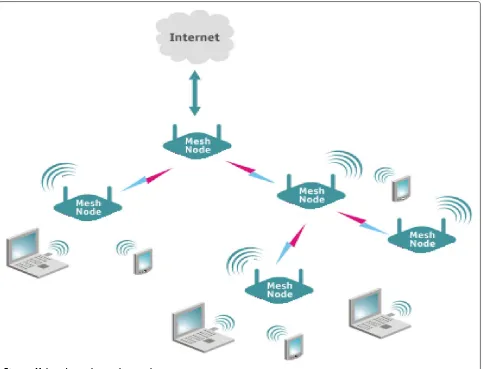
Wireless mesh networks (WMN) will be the next self-configuring backhaul providing Internet access for last mile users through multi-hop forwarding (Figure 1). Mesh networks however suffer from wireless interference due to the broadcast nature of the wireless media that may degrade their performance significantly.
Multi-radio WMNs are able to offer higher net-work capacity using different non-overlapping channels provided by IEEE 802.11 standards in the unlicensed bands [1]. Although there are several non-overlapping channels available, the number of channels that can be used simultaneously by a single node is limited by the number of radio interfaces installed on the node. There-fore, a mechanism which selects the best channel, in terms of interference, among all available channels, is needed in order to achieve the maximum possible network performance.
Technical solutions for multi-hop wireless networks are being specified in IEEE 802.11s [2]. IEEE 802.11s is developed as an extension of the successful IEEE 802.11 standard for WLANs (wireless local area networks) [1].
*Correspondence: [email protected]
1Department of Computer Architecture, Universitat Politecnica de Catalunya, Barcelona 08034, Spain
Full list of author information is available at the end of the article
IEEE 802.11s defines the mesh operation in a single chan-nel although multi-radio mesh routers can form different meshes. The connection between different meshes is pro-vided via bridging. Mesh routers can initiate the channel switching mechanism which moves the mesh, or part of it, to another channel. The routers which do not want to follow the channel switch request may join another mesh. Channel switching may help mesh routers to avoid the external interference but does not reduce the internal interference between routers which belong to the same mesh basic service set (MBSS), since it moves the MBSS to another channel. However, frequent channel switch-ing may degrade the mesh performance due to the high overheads that it implies [3].
In multi-radio mesh networks, channel assignment (CA) is a mechanism which tries to find a feasible map-ping between wireless channels and radio interfaces at each node with the aim of maximizing the capacity of the network.
A channel assignment solution must satisfy the follow-ing conditions to be feasible:
• The number of channels assigned to a node must be equal or less than the number of radio interfaces it has.
• The neighboring nodes must have at least a radio at a common channel to be able to communicate with each other.
Figure 1Multi-radio wireless mesh network.
Based on the time duration between consecutive runs of the channel assignment protocol, CAs are categorized as static, dynamic, and semi-dynamic [3].
Most of the CAs proposed in the literature fall into static category [4-13], where nodes tune their radios to cer-tain channels permanently. Static CAs are easy to deploy but unsuccessful to cope with the changes in the wireless environment [4].
Dynamic channel assignments [14,15], on the other hand, enforce the nodes to switch their interface dynami-cally from one channel to another between successive data transmissions. Therefore, they require tight synchroniza-tions among nodes. Dynamic approaches are only used for single radio nodes working over multiple frequencies, since they cannot exploit the advantages of multi-radio networks [3].
Static CAs can be easily extended to be semi-dynamic [16-26] if the node refreshes the channels assigned to the radios on a regular time period. Semi-dynamic CAs adapt fast to the changes in the traffic
pattern and the interference on the wireless medium from both internal and external sources. However, to maintain the network connectivity, neighboring nodes are sup-posed to share a common channel [16,27].
Hybrid CAs apply a semi-dynamic channel assignment to the fixed radio interface of each multi-radio node while the other radio is controlled dynamically. Wireless nodes which use hybrid CAs may not share a common chan-nel with their neighbors, since the dynamic radio switches to the channel of the neighboring nodes to make the connection.
Implementing a multi-radio multi-channel mesh net-work is very challenging due to the following reasons:
• The transmitting and receiving antennas installed on a single mesh node should be separated enough to reduce the noise of the transmitter on its own receiver [27,28].
frequencies over each other due to lack of prefect filtering at the antenna [28].
• The media access control (MAC) layer of the IEEE 802.11 standard should be modified to support channel assignment mechanisms [3].
• The routing protocol must be modified to take the advantage of the underlying channel
assignment [6,16,17,27].
Channel assignment mechanisms are usually evalu-ated via simulations due to the multiple considera-tions and complex scenarios required to evaluate them [7-10,13,22-25]. However, most of the current net-work simulators do not support multi-radio routers nor dynamic re-configuration of the radio interface, requiring modifications into their core level to allow the evaluation of CA mechanisms [29].
ns-3 [30] is a young simulator which allows the wire-less mesh nodes to be equipped with more than one radio interface and makes it possible to change the frequency of the radio during the simulation run time. Although those features are necessary in order to simulate a multi-radio multi-channel network, they are not enough for simulat-ing hybrid or dynamic CA mechanisms. Multi-radio mesh networks simulated in ns-3 based on the recently pub-lished standard, IEEE 802.11s [2], are assumed to share common channels. The ns-3 modules for IEEE 802.11s can be used to simulate static or semi-dynamic CAs, but they are insufficient for dynamic or hybrid CA. As in IEEE 802.11s, the peer links are formed over common chan-nels, and the peer management protocol must be changed to be able to send beacons for neighboring mesh points which do not share any common channel. This modifica-tion is incompatible with the IEEE 802.11s standard which assumes that mesh points operate in a single channel [2]. According to the IEEE 802.11s standard, multi-radio sta-tions form different meshes on different channels, which are unified in a single LAN using the layer 2 bridging. We consider the problem of simulating hybrid CAs without restricting our work to IEEE 802.11s mesh networks.
In this work, we show in detail how to simulate a hybrid channel assignment protocol using ns-3 simulator without any need to modify the simulator’s source code (Section 2). This work is the first step in clarifying the necessary components and considerations for building a dynamic/hybrid CA in ns-3. Furthermore, we have also focused on the validation and verification mechanisms for simulation-based studies, which are the two aspects that have not yet been considered by the research community when it comes to implement the CA mechanism. We use the simulator version 3.9 released on August 2011. As a specific example, we present the simulation of the channel assignment proposed in [25,26] (Section 3). This exam-ple is used to explain the simulation verification and the
validation of the CA model (Sections 4 and 5). A brief summary of other CA protocols proposed in the literature which could also be implemented following the presented approach is described in Section 6, and conclusions are presented in Section 7.
2 Simulation components for multi-radio mesh networks
In this section, we introduce the required extensions to ns-3 simulator [30] for simulating hybrid CA mechanisms. These extensions include the basic functions on top of which the CA mechanism can be implemented, in addi-tion to presenting how to simulate external interference for adaptive CAs.
2.1 Multi-radio wireless nodes
Multi-radio wireless mesh nodes are the required basic building blocks of the simulation scenarios. Figure 2 shows a wireless mesh node equipped with several radio interfaces.
The figure depicts a general cross-layer channel assign-ment protocol that interacts with the components of the simulation: traffic generators, routing protocol, and the channel sensing mechanism.
In Program 1, it can be seen how to make a multi-radio node (MRNode) in ns-3, whereIis the number of radio interfaces which must be installed on a node. Note that in ns-3, a unique ID starting from 0 is automatically assigned to each radio interface.
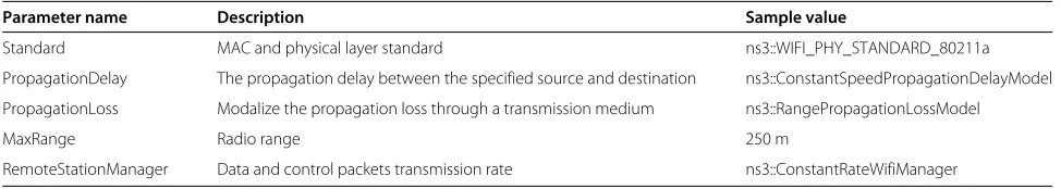
Table 1 shows a sample configuration of the MAC and physical layers, which makes IEEE 802.11a-based radio interfaces. The radio propagation model is set to the fixed range propagation model with a maximum range equal to 250 m. We also define a single transmission rate equal to 6 Mbps for data and control packet transmission. Note that this configuration is not fixed and it can be set to any of the propagation and channel loss models that ns-3 supports [30].
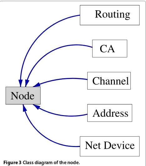
Lines 8 and 9 of Program 1 show how any other object (CA mechanism, routing protocol, etc.) is created and aggregated to the wireless mesh node. Figure 3 shows the class diagram of a node in ns-3.
multi-Figure 2Node object.
radio node to make it possible to simulate the channel assignment mechanism.
2.2 Network devices
2.2.1 Configuring the radio interface
ns-3 indicates each channel with a uniqueID, which starts from 0. By default, the channel assigned to all radios in a node is set to 0. To re-configure the channel assigned to a radio interface, a node has to change the ID of the default channel in the physical layer of the radio interface. All channels in ns-3 are supposed to be non-overlapping.
Program 2 shows the process of assigning channelcto the first radio interface (netDevice) installed onMRNode.
Note that if the interface is busy due to sending or receiving, it is not possible to switch to another frequency. Program 2 checks the status of the device (line 5) before setting the new channel.
It is also possible to acquire the remaining time until the device gets idle (line 9) and set the channel afterwards (line 11).
2.2.2 Data service components
To transmit packets in a multi-radio multi-channel archi-tecture, where wireless nodes use a dynamic or hybrid CA, some extra tasks must be done to acquire the chan-nel on which the packets must be sent, in addition to computing the time for switching a radio interface to the desired channel. Figure 4 shows the main process that a node follows to deliver packets on the presented multi-radio multi-channel architecture. It comprises three steps: destination channel query, time stamp assignment, and packet queueing.
Unlike single-channel networks, a node in a multi-channel architecture needs to consider the possibility of having next hop neighbors on different channels. There-fore, to forward a packet, a wireless mesh node needs to
Table 1 Physical and MAC layer configuration
Parameter name Description Sample value
Standard MAC and physical layer standard ns3::WIFI_PHY_STANDARD_80211a
PropagationDelay The propagation delay between the specified source and destination ns3::ConstantSpeedPropagationDelayModel
PropagationLoss Modalize the propagation loss through a transmission medium ns3::RangePropagationLossModel
MaxRange Radio range 250 m
Figure 3Class diagram of the node.
Routing Port
Packet
Destination Channel
Query
Time Stamp
Assignment
Packet Queuing
Data Delivery
For MR−MC Architecture
Figure 4Data services for channel assignment mechanism.
know the channel on which it can send the packet, in addition to the address of the next hop mesh node.
The Destination Channel Query function finds the
channel on which the packet must be sent. A Packet Queuingmechanism buffers packets and keeps them until the sender switches one radio interface to the correspond-ing destination channel. To avoid saturation in a given queue, the packets that have been waiting for a period of time exceeding a certain threshold are dropped from the queue. For such purpose, a time stamp is assigned to each new arriving packet and used as a reference to drop the packets.
a. Destination Channel Query: Multi-radio nodes keep the following information about their neighbors in addition to their address:
• The number of radio interfaces a node has • The channel assigned to each radio interface • At which time each node will switch from one
channel to another
• At which time each node can receive packets on each channel.
The mentioned information is kept in the Neighbor Table. To forward a packet, a node gets the receiving channel of the next hop neighbor. With this information, the node can tune a radio to that channel and send the pending packets.
Nodes use control messages to update the information about their neighbors in theNeighbor Table. This is nec-essary for the adaptive channel allocation mechanisms, where a node changes the channel of its radio interface frequently.
Every time that a node informs its neighbors about switching the channel of its radio interface, the neighbors will update the entry in theNeighbor Table.
In a multi-channel architecture, nodes may need to monitor the available channels to acquire the list of busy channels. When forwarding a packet, the node should make sure that the receiver is not in the monitoring mode. Therefore, the node needs to keep the next monitoring period for all of its neighbors to avoid initializing any transmission.
b. Time Stamp Assignment: Nodes must time stamp the packets waiting to be sent over a certain channel; in case the destination channel is busy, the older packets must be discarded to avoid saturation. Therefore, it is possible to control the length of the buffers.
The time stamp assigned to each packet is equal to the time at which the packet was received from the routing agent (Tenqueu(p)). We define Twait(p) as the maximum amount of time that a packet is allowed to stay in the buffer before it is transmitted over the wireless media. To remove the old packets, a node checks the current time of the system (Tcurrent) and deletes those packets that Tcurrent>Tenqueu(p)+Twait(p).
To avoid the queues from getting saturated in high traffic rate, nodes may select a smaller value forTwait(p).
c. Data Queuing: In multi-radio multi-channel networks, the number of available frequencies is bigger than the number of radio interfaces at each router (|C|>I). There-fore, the neighboring nodes may set their antennas over different channels. A wireless mesh node which has traf-fic for more than one neighbor, might need to switch to different channels to be able to deliver its packets to the next hop. During the time that a node transmits data over a channel, packets destined for other channels must be buffered to be sent later.
We create sequential first-in, first-out queues for buffer-ing packets in ns-3 for different channels. Each queue corresponds to one of the available channels. The defined queues have the ability to eliminate the old packets auto-matically as described in Section 2.2.2.
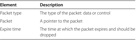
Table 2 shows the fields of each element of the queue with a brief description.
2.3 External interference and channel sensing
Simulating two separate wireless networks which inter-fere with each other is not possible in ns-3. Difinter-ferent wireless networks simulated in the same scenario do not have any effect over each other since ns-3 treated them separately.
For an adaptive channel assignment, we have a scenario where each channel is occupied by different amounts of interference. Nodes estimate the amount of interfer-ence through sensing or monitoring all channels at the
Table 2 Packet buffer elements
Element Description
Packet type The type of the packet: data or control
Packet A pointer to the packet
Expire time The time at which the packet expires and should be dropped
same time [16,22]. Simulating this scenario is possible only if the interference threshold is set separately for each channel.
To simulate the external interference in ns-3, we can consider the external interference as it was noise, and therefore, we can model it by properly adjusting the noise figure and the error rate parameter for each radio inter-face [30]. However, using this approach, we are not able to differentiate between the signal propagation, the noise effects, and the external interference, which introduces an unnecessary complexity to understand the results, as we can simply avoid by developing an independent module.
Therefore, to simulate the external interference on wire-less channels, we have created an Interference Emulator for each channel (Program 4). TheInterference Emulator is based on a semi-Markov model of the possible channel status (Figure 5), where the status of a channel is consid-ered as either Busy or Idle. The expected idle duration (Tidle) of a random variable that follows an exponential distribution with rateμis given by
FTidle(t)=1−e−μt. (1)
The emulator keeps the channel Busy for a prede-fined period of time (BusyDuration) according to IEEE 802.11k [31]. The duration of Idle state is determined using an exponential random variable with the mean equal toMeanIdleTime.
In the constructor (line 8 of Program 4), a timer is ini-tialized to call theChangeStatusfunction when it expires. Initially, the delay of the timer is set to an exponen-tially distributed random variable with the mean equal to MeanIdleTimems.
ChangeStatus changes the status of the channel from Idle_State to Busy_State or vice versa. It sets the timer
to BusyDuration after setting the channel status to
Busy_State. Whenever it changes the channel status to
Idle_State, it sets the timer to a randomly selected duration.
To monitor a channel, a node checks the Interference Emulator Statusattached to the channel during the sens-ing period.
The amount of interference over a channel, induced by an external network, can be varied by setting different values forMeanIdleTimeandBusyDuration.
2.4 Routing modifications
When simulating multi-radio multi-channel WMNs, con-sidering a proper routing protocol is challenging. The routing has to be considered as a joint problem with the channel assignment [16,18-20], since any change in the channel radio mapping affects the quality of the links between nodes and may trigger the routing protocol to re-route the traffic. On the other hand, the changes in the traffic pattern have an impact on the next decision of the channel assignment protocol. Therefore, the routing pro-tocol and the routing metric must be modified to adapt to the channel assignment [6,32].
In ns-3, the available routing protocols are not applica-ble for multi-radio wireless networks when using dynamic or hybrid channel assignment. Nevertheless, as we are only focusing on fixed WMNs, where nodes are fixed or have limited mobility, the static routing is a simple way to avoid complexity related to the dynamic rout-ing protocols. The global routrout-ing simulated in ns-3 pro-vides static routing only for wired networks by filling the routing tables at the beginning of the simulation. In the case of wireless networks, there is no static routing since the topology of a wireless network is determined by the propagation model and other parameters at run time [30].
Therefore, we have attached a static routing table to each node and initialized it using Shortest Path First (SPF) algorithm, minimizing the number of hops between each node and any other destination. Each node knows about the next hop node on the paths to all other nodes in the network. Program 5 shows an entry of theRouting Table. The routing table includes channel information of the next hop nodes. This will give flexibility to routing proto-cols which apply channel information in the metrics [6]. It is also very useful when the next hop node has more
than one receiving radio, and hence, it is accessible over multiple channels.
TheRouting Tablecan be filled either using a file con-taining all shortest paths between all nodes or during the simulation using route request messages. We have used a file which is filled by R numerical tool [33] feeding the position of nodes in the network.
The routing header which is attached to each packet has the following elements:
• Sequence number
• Node ID of the source • Node ID of the destination
• Node ID of the next hop device to the destination • The time of originating the packet.
The relay nodes on the path from the source to the des-tination update the ID of the next hop node in the header and forward the packet.
2.5 Synchronization
In a dynamic or hybrid CA, the synchronization can be achieved through exchanging messages either using a fixed radio over a common channel or using the data channels. Since each node assigns a channel to its receiv-ing radio which differs from its neighbors, nodes must be aware of the channels which are being used by their neigh-bors and any upcoming switching to the new channel, in case of using adaptive CAs. Moreover, if nodes sense the medium to detect the external interference, they must be aware of the sensing period of their neighbors to avoid ini-tiating any transmission on the same channel that is being sensed for detecting external interference.
We use the termeventto refer to upcoming switching a channel or sensing a channel event.
We use control messages to make nodes aware of upcoming events. The key point is, instead of reporting the time of each event, nodes report the remaining time slots until the event. Neighboring nodes upon receiving the message add the time slots reported in the received control message to their local time to acquire the time of each event.
This method works fine in ns-3, and nodes are able to synchronize the events with their neighbors.
3 An example of CA implementation: SICA
In this section, we provide a brief explanation about Semi-dynamic Interference aware Channel Assignment (SICA) mechanism as presented in [25,26]. We explain in detail how each component of SICA is implemented in ns-3. Notice that, in Sections 4 and 5, we tackle the challenge of validating and verifying the simula-tion model for SICA. We introduce a novel Markov model to validate the SICA results from the theoreti-cal point of view. We also develop a new automated test module to verify the implementation of SICA in the simulator.
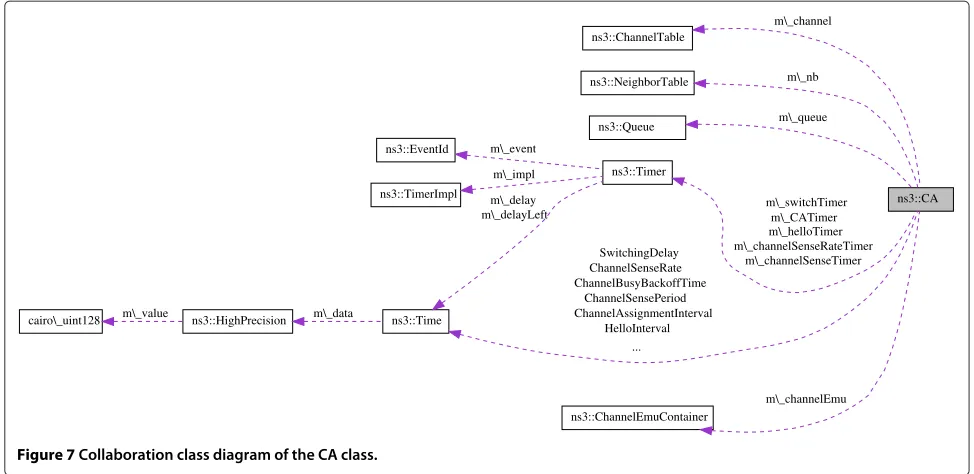
Figures 6 and 7 show the class diagram and the col-laboration diagram of using the defined classes to model a channel assignment protocol. In the following section, we show with more detail the simulation of a channel assignment mechanism, called SICA, in ns-3 using the components introduced before. Moreover, we provide the details of some important process regarding the Data ForwardingandChannel Selection.
SICA is a protocol proposed and simulated in ns-3 for wireless mesh networks [25,26]. The source code of SICA is available and can be accessed at [34].
SICA is implemented in a network where nodes are equipped with two radio interfaces; each one is able to use a setC(with cardinality|C| >1) of non-overlapping
CA
NeighborTable
RTABLE
ChannelEmu
CAHelper
ChannelTable
Queue ns3::Queue
CAHelloHeader
Figure 6Class diagram of the CA class.
channels. The radios will be referred to as the receiving radioand thetransmitting radio, and denoted byRandT, respectively.
The aim of the channel assignment mechanism is to select the channels which suffer less interferences in terms of both internal and external interference. The channel assignment mechanism selects and assigns a channel to the Rradio of each node. Then, the node switches the T radio according to the receiving channel of its neigh-bors to start transmission. After a channel switch, the T radio remains on the same channel until all packets, which are addressed to the same destination node, have been sent or until a maximum period of time has expired [25].
Nodes estimate the amount of external interference on a channel via sensing the channel. Then, they use control packets calledHelloto exchange channel sensing informa-tion and inform their neighbors about upcoming interface switching for the receiving radio (R).
3.1 External interference estimation
Using theChannel Emulators(Section 2.3), the status of a channel can be monitored as Busyor Idle. Each node monitors the channel’s status for its receiving radio (R) once in each sensing period of length TSS seconds. For monitoring a channel c, the node checks the status of the correspondingChannel Emulator(ce) at a pre-defined rate (TSRate).
At the end of the monitoring period, the node estimates the amount of external interference over a channel (Bext) using Equation 2.
Bext(c)=
Tbusy(c) Tbusy(c)+Tidle(c)
(2)
Tbusy andTidle show the duration of theBusyand the Idlestates, respectively.
Note that each node senses only one channel during the monitoring period. It then sends this information to its neighbors, and as its neighbors do the same, it gathers information about other channels via the control packets received from its neighbors (see Section 3.3).
The internal interference is estimated based on the Interference Protocol Model proposed in [35]. Each node is informed by its neighbors about the current channel of their receiving radio. Therefore, a nodeican calculate the number of neighboring nodes over channelc(Ri(c)). Then, the node estimates the density of interfering nodes on channelcbyRi(c)
Ni whereNirepresents the total number
of neighbors of nodei.
ns3::CA ns3::ChannelTable
m\_channel
ns3::NeighborTable m\_nb
ns3::Queue m\_queue
ns3::Time
SwitchingDelay ChannelSenseRate ChannelBusyBackoffTime
ChannelSensePeriod ChannelAssignmentInterval
HelloInterval ... ns3::Timer
m\_delay m\_delayLeft
ns3::HighPrecision m\_data cairo\_uint128 m\_value
ns3::ChannelEmuContainer
m\_channelEmu m\_switchTimer m\_CATimer m\_helloTimer m\_channelSenseRateTimer
m\_channelSenseTimer ns3::EventId m\_event
ns3::TimerImpl
m\_impl
Figure 7Collaboration class diagram of the CA class.
3.2 Channel selection mechanism
The channel selection mechanism is developed as a repeated game which uses the interference estimation information and selects the best possible channel for the receiving radio of a node.
Initially, the channel selection mechanism calculates and assigns a weight to all available channels based on the amount of internal and external interference esti-mated over a channel. Then, the weights are updated using the multiplicative weight update technique proposed in [36,37].
We definewt(c)as the weight assigned to channelcat timet. The channel assignment computes the probability of selecting a channel as
Pt(c)= wt(c) c∈Cwt(c)
. (3)
Initially, all weights are set to 1; thus, the probability of selecting any channel is identical. After selecting a chan-nel, the node gathers information from its neighbors and updates the loss that it suffered. Then, the weights are updated as follows:
wi,t(c)=wi,t−1(c) βMi(c), (4)
whereMi(c)is the loss suffered by nodeiconsidering the external and internal interference over channelc[25], and βis the game parameter in the range of(0, 1)[37].
Then, SICA selects a random channel considering the probability of each channel as shown in Program 6.
Program 6 computes and sorts the probability of select-ing a channel accordselect-ing to Equation 3 (lines 11 to 18 and line 20). Then, it sorts the list of available channels based on the weights (probabilities) assigned to each channel (line 19). Line 21 computes the cumulative probability vector by adding up each probability value with all prob-abilities lower than it. Then, the probprob-abilities are fed to the empirical random variable generator (lines 22 and 23) which generates a random number as an index for the available channels’ list (line 24 of Program 6).
3.3 Control packet elements
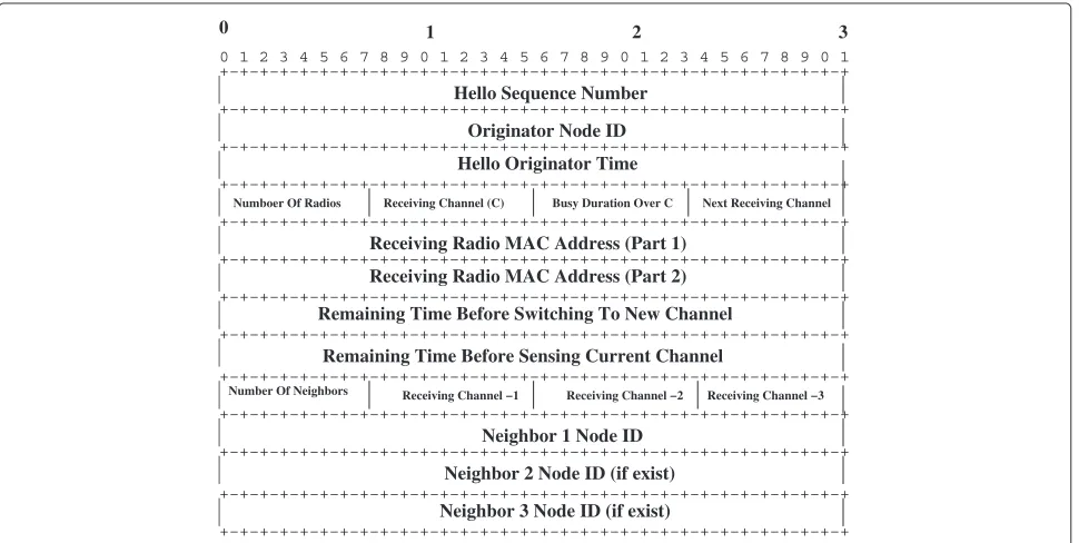
by all nodes. In SICA, the synchronization is achieved through exchanging packets over the data channels. Since each node can assign a different channel to its receiv-ing (R) radio, nodes must be aware of the channels used by their neighbors’ R radios. In SICA, a node broad-casts Hello packets to report the channel of its Rradio to its neighbors. Figure 8 shows the content of a Hello packet.
In addition to the receiving channel announcement, Hellopackets are used to inform about the channel sens-ing information and the receivsens-ing channel of the neighbor-ing nodes, so a node can compute the external and internal interference for each channel. In order to do that, there is a field in each packet which contains the amount of exter-nal interference over the receiving channel estimated by the node. The number of neighbors and the channels of their receiving radio is also added at the end of eachHello packet.
The remaining time before a node switches itsRradio to another channel and the remaining time before the node starts sensing the current channel are also announced via Hellopackets. The announcements inform the neighbor-ing nodes about upcomneighbor-ing channel switchneighbor-ing or sensneighbor-ing events.
3.4 Data and control transmission
For each channel c ∈ C, SICA maintains two
sequential first-in first-out queues for buffering packets (Section 2.2.2): control packet queue (Qctrl(c)) and data
packet queue (Qd(c)). Qctrl(c) has higher priority than Qd(c). The source and each node in the middle of the path to the destination push each packet to the correspond-ing queue attached to each channel. Each packet is time stamped when it is pushed to the queue. Using the time stamp as a reference, packets that remain in the queue for a longer time than a certain threshold are discarded to avoid saturation (see Section 2.2.2).
When the transmitter radio switches to a channel, it fetches the stored packets from the queues and sends them until there is no packet left in the queues or until a maximum amount of time has elapsed [25]. Program 7 shows how packets are sent over a channelc.
0
Numboer Of Radios
+−+−+−+−+−+−+−+−+−+−+−+−+−+−+−+−+−+−+−+−+−+−+−+−+−+−+−+−+−+−+−+ +−+−+−+−+−+−+−+−+−+−+−+−+−+−+−+−+−+−+−+−+−+−+−+−+−+−+−+−+−+−+−+
Number Of Neighbors
Receiving Radio MAC Address (Part 1) Receiving Radio MAC Address (Part 2) Remaining Time Before Switching To New Channel
Remaining Time Before Sensing Current Channel
+−+−+−+−+−+−+−+−+−+−+−+−+−+−+−+−+−+−+−+−+−+−+−+−+−+−+−+−+−+−+−+ +−+−+−+−+−+−+−+−+−+−+−+−+−+−+−+−+−+−+−+−+−+−+−+−+−+−+−+−+−+−+−+ +−+−+−+−+−+−+−+−+−+−+−+−+−+−+−+−+−+−+−+−+−+−+−+−+−+−+−+−+−+−+−+ +−+−+−+−+−+−+−+−+−+−+−+−+−+−+−+−+−+−+−+−+−+−+−+−+−+−+−+−+−+−+−+ +−+−+−+−+−+−+−+−+−+−+−+−+−+−+−+−+−+−+−+−+−+−+−+−+−+−+−+−+−+−+−+ +−+−+−+−+−+−+−+−+−+−+−+−+−+−+−+−+−+−+−+−+−+−+−+−+−+−+−+−+−+−+−+ +−+−+−+−+−+−+−+−+−+−+−+−+−+−+−+−+−+−+−+−+−+−+−+−+−+−+−+−+−+−+−+ +−+−+−+−+−+−+−+−+−+−+−+−+−+−+−+−+−+−+−+−+−+−+−+−+−+−+−+−+−+−+−+ +−+−+−+−+−+−+−+−+−+−+−+−+−+−+−+−+−+−+−+−+−+−+−+−+−+−+−+−+−+−+−+ +−+−+−+−+−+−+−+−+−+−+−+−+−+−+−+−+−+−+−+−+−+−+−+−+−+−+−+−+−+−+−+ +−+−+−+−+−+−+−+−+−+−+−+−+−+−+−+−+−+−+−+−+−+−+−+−+−+−+−+−+−+−+−+
Hello Sequence Number
3 2
1
Originator Node ID Hello Originator Time
Neighbor 1 Node ID Neighbor 2 Node ID (if exist) Neighbor 3 Node ID (if exist)
Receiving Channel (C) Busy Duration Over C
Receiving Channel −2 Receiving Channel −1
0 1 2 3 4 5 6 7 8 9 0 1 2 3 4 5 6 7 8 9 0 1 2 3 4 5 6 7 8 9 0 1
Next Receiving Channel
Receiving Channel −3
TInterfaceReadyToSend(line 4) is a function which gets the ID of the channel and the estimation of the required time to send a packet by theTradio and checks whether it is possible or not to send a packet over the channel.
In the following cases, the TInterfaceReadyToSend returnsFalse, which prevents the node from sending pack-ets over channelc:
• The channel is being sensed by any of the neighbors. • The channel is busy due to the external interference. • The T interface did not switch to the channel
successfully.
• The estimated transmission time is less than the remaining time over the current channel.
4 Validating the game model
Model validation deals with building the right model. It is the process of determining whether a simulation model is an accurate representation of the system. Validation can be obtained based on mathematical proof of correct-ness by comparing the results of the model with other models [38,39].
The channel assignment in SICA is modeled as a repeated game, where nodes compete to occupy the most vacant channel (as explained in detail in Section 3.2). The game is played repeatedly in a sequence ofgame rounds. In each round, the player plays a mixed strategy based on the weights assigned to each channel.
In the following section, we use a Markov chain model to prove that the results of the game are consistent with how the system operates. Moreover, the model compari-son makes it possible to find under which conditions the game converges to a steady state and which parameters have greater effect on the performance.
We simulate the game model using R numerical tool [33] and compare the result with the results obtained using the Markov model to compute the probability of selecting channels.
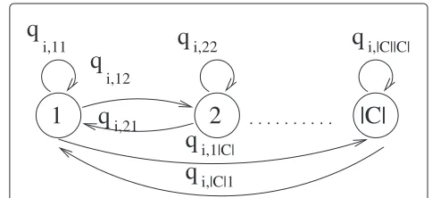
We define the process of selecting a channel for a radio interface at each node as a Markov chain.
Figure 9 shows the Markov chain that models how a node selects the channels. The channel set (strategy set) was mapped to the state space of the Markov model. The payoffPi = 1−Mi is considered as the reward for the transition between channelcand´cby nodei.
The probability of having a node at any of the state is given by the Boltzmann distribution [40,41]. Equation 5 shows the transition probability from statecto´c, which is related to the reward of the destination channel normal-ized by the total reward of all channels:
Qi,cc´=
Hereλis the learning parameter which means that small values ofλenable the player to choose the optimal strat-egy more accurately. For our model, we defineλ=1−β, where β is the learning parameter used for the game model of SICA (see Section 3).
Using the R tool, we have simulated the game-based learning algorithm of SICA for a node. We defineρ´as the final probability vector of selecting each channel equal to the mixed strategy vector obtained for the node. We com-pareρ´, obtained for different rounds of SICA algorithm, with stationary channel transition vectorρ, obtained from the Markov model (Figures 10 and 11). Moreover, we run SICA in ns-3 simulator and report the probability distri-bution of selecting channels over 200 s of simulation run. (Figures 12 and 13).
Figure 10 shows the probability of selecting a channel at each node. For clarity, we show the available bandwidth of each channel with a red line at the same figure with the probability distribution of selecting a channel. As shown, the available bandwidth in each channel decreases linearly from channels 1 to 8. The righty-axis shows the available bandwidth related to the total bandwidth of a channel, while the lefty-axis shows the probability of selecting the channel.
Figure 10 shows that the weighted learning algorithm matches quite closely the result from solving the Markov model after 100 rounds forβ=0.9.
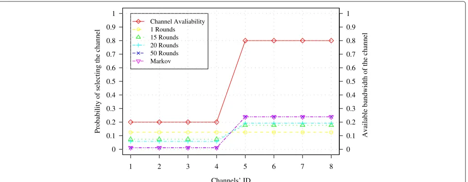
We examine SICA and the Markov model for the case that 50% of the channels (channels with the IDs from 5 to 8) are occupied by the external interference. The inter-ference occupies 80% of the bandwidth of those channels, while channels with the IDs from 1 to 4 are almost free.
Figure 11 shows that in this specific scenario, when the decision about selecting the best channels is more clear, the learning algorithm of SICA converges to the Markov solution much faster, in this case only after 15 rounds.
The other technique for validating a model is showing the model operation behavior over time [38]. To study the behavior of SICA over time, we simulate SICA using ns-3 simulator for a grid network of size 5×5 nodes and 2
i,1|C|
1 2 3 4 5 6 7 8 0
0.1 0.2 0.3 0.4 0.5 0.6 0.7 0.8 0.9 1
0 0.1 0.2 0.3 0.4 0.5 0.6 0.7 0.8 0.9 1 Channel Avaliability 1 Round
20 Rounds 50 Rounds 100 Rounds Markov
Channels’ ID
Probability of selecting the channel Available bandwidth of the channel
Figure 10The probability of selecting a channel.The red line shows the available bandwidth of each channel for game rounds.
CBR traffic flows of 100 kbps. The results are obtained averaging over 10 simulation runs, and the error bars show the 90% confidence interval.
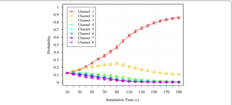
Figure 12 shows how the probability of selecting a tar-get channel changes over time, when a different amount of external interference is introduced on each channel. Specifically, the channel with the higher ID suffers more external interference. The figure shows that the nodes tend to select the channel which offers more bandwidth, which is the expected behavior of any CA.
Figure 13 shows the average probability of selecting each channel over time when the external interference is intro-duced on the first four channels (channels with the IDs from 1 to 4) while other channels are free. The figure
shows that the probability of selecting any of the busy channels tends to 0 over time, while the probability of selecting any of the free channels (channels with the IDs from 5 to 8) increases to 0.25 which confirms the results shown in Figure 11. Moreover, it can be observed how SICA achieves a proportional utilization of the four free channels.
5 Verifying the simulation model
Model verification ensures that the computer program-ming and implementation of the conceptual model are correct [38]. Assertion checking is one of the dynamic verification techniques for simulation model. Unlike the static techniques which analyze the program to
1 2 3 4 5 6 7 8
0 0.1 0.2 0.3 0.4 0.5 0.6 0.7 0.8 0.9 1
0 0.1 0.2 0.3 0.4 0.5 0.6 0.7 0.8 0.9 1 Channel Avaliability
1 Rounds 15 Rounds 20 Rounds 50 Rounds Markov
Channels’ ID
Probability of selecting the channel
Available bandwidth of the channel
10 30 50 70 90 110 130 150 170 190 0
0.1 0.2 0.3 0.4 0.5 0.6 0.7 0.8 0.9 1
Channel 1 Channel 2 Channel 3 Channel 4 Channel 5 Channel 6 Channel 7 Channel 8
Simulation Time (s)
Probability
Figure 12The probability of selecting a channel for a node over time.
determine if it is correct (syntax analysis), dynamic verifi-cation deals with checking the correctness of the values which are obtained after executing the program [38,42].
To verify the simulation in ns-3, we design a state space explorer (SSE) which is invoked by the major events that happen in the simulations and performs state checking to verify the correctness of the simulation.
We assume that the simulation, as a system, consists of a group of entities joined together to accomplish the packet delivery goal and hence virtually represents the operation of the real system.
We consider each radio interface as anentitywith the following attributes:
• The frequency channel it is using • The number of packets it has received • The number of packets it has sent • The number of packets it has dropped.
The State of the system (st) is the complete descrip-tion of the system at any time which includes all enti-ties and values of their attributes. We consider those
10 30 50 70 90 110 130 150 170 190
0 0.1 0.2 0.3 0.4 0.5
Channel 1 Channel 2 Channel 3 Channel 4 Channel 5 Channel 6 Channel 7 Channel 8
Simulation Time (s)
Probability
attributes which are relevant to the objective of inter-est.strepresents a function of all entities which assigns a value to all attributes. We consider that ξ con-tains all possible states of the system and call it state space.
TheEvent(et) is any occurrence which changes the state of the system. In our model, we consider the following events:
• Sending a packet (Send, unconditional event) • Receiving a packet (Receive, conditional,
et=Receive|et0 =Send t0<t)
• Dropping a packet (Drop, conditional , et=Drop|et0 =Send t0<t)
• Changing the channel of the radio interface (Channel Change, unconditional event).
We define E as the set containing all above events. The first three events occurred between two entities: the sender and the receiver.
AnAssertion is a property which must be held for all states of the system to be able to prove the correctness of the simulation.
For the simulation of the channel assignment protocol, we define the following assertions:
• Only one channel must be assigned to a radio. In a hybrid CA, after assigning a channel to a radio, the radio may not switch immediately to the new channel since the node must inform the neighbors about the upcoming switching. Moreover, if a radio is receiving data, the node will not switch until the end of the data transmission. Therefore, CA must avoid assigning a new channel to a radio before the previous channel assignation took effect.
• There must be a common channel between the
sender radio and the receiver radio at any given time. In dynamic and hybrid CAs, the data transmission mechanism must be sure that the radios of the nodes are tuned to the same channel before the transmission starts. This must be achieved through an appropriate synchronization and switching mechanism.
We have designed SSE in ns-3, which starts from the ini-tial state of the system and reaches the successor state fol-lowing the simulation events, and checks for any violation from the assertions.
s0 is defined as the initial state of the simulation. We define ´s as explored bys0 if ´s is the successor state of the system after the triggering event e (e ∈ E), and we notate it as s0
e
→ ´s. The event handler is triggered by any of the events in E, and it calls the state con-trol procedure to check the assertion of the successor event.
fi,cis defined as the number of receiving radios of nodei which are tuned to channelc. For any nodei, the assertion condition is
|C|
k=1
fi,k=Ii, ∀i∈N, (6)
whereIirepresents the number of radio interfaces of node i.
For any transmission pairs(i,j), the assertion condition is
∃c∈C, fi,c.fj,c=1. (7)
Algorithm 1 shows the state check algorithm which is triggered by sending, receiving, or dropping packet events and checks if any violations happen from the assertions.
Algorithm 1:StateCheck1 (St,et−1,P)
Input: The current state of the system at timet(St),
the last event which moved the system to state St(et−1), and the pointer to the packet in the case of sending and receiving events (P) Output: Whether the assertion holds or not
ifSt==S0then
Write(‘Assertion holds’); exit(0);
end end
Write(‘Assertion violated’); exit(1);
end
Algorithm 2:StateCheck2 (St,et−1)
Input: The current state of the system at timet(St)
and the last event which moved the system to stateSt(et−1)
Output: Whether the assertion holds or not
ifSt==S0;
then exit(0); end else
N=et−1−>Node(); C=N−>Channels(); I=N−>Radios();
ifC<=Ithen
Write(‘Assertion holds’); exit(0);
end
Write(‘Assertion violated’); exit(1);
end
Figures 14 and 15 are obtained running State Space Checkalgorithm (Algorithm 1) for checking the simula-tion events of SICA. The simulasimula-tion parameters are the same as the parameters considered for Figure 13.
Figure 14 shows the state space control forSend,Receive, andDropevents. The figure depicts the number of events that happened during 200 s of simulation run and the number of events for which the assertion holds. The figure shows that SICA does not violate any of the assertions.
Figure 15 shows the number of packets which have been sent, received, or dropped on each channel when the external interference is introduced over channels with the IDs from 1 to 4. The figure confirms that SICA makes the network use the capacity of the free channels efficiently.
Figure 16 shows the average number of radio inter-faces over each channel during the simulation time. Note that the simulation parameters are the same as those in Figure 15. The figure shows that the number of radio interfaces over the set of channels that are occupied by external interference decreases over time. It proves that the channel assignment successfully detects and avoids the channels which are occupied by external interference as it is expected.
Figure 17 shows the average number of packets (with a size of 1 kb) in each data queue over the time. The figure shows that the proposed data delivery mechanism ensures that the number of waiting packets in each chan-nel is lower than the default maximum queue size in ns-3 (100 packets) [30]. In addition, the maximum number of packets waiting in a queue at the beginning of the simu-lation (marked in red), happened over those channels that are kept busy by external interference.
6 Related work
Channel assignment is a problem that must be solved toward the implementation of wireless mesh networks, and it has been studied extensively during the last years. Although many solutions have been considered for chan-nel assignment [3-13,16-24,43-47], few proposals are adaptive to the changes in the wireless environment such
Send Receive Dropped
Total Events Assertion Holds
Events 0
5000 10000 15000 20000 25000
1 2 3 4 5 6 7 8
Channels’ ID 0
1000 2000 3000 4000 5000 6000
Send Receive Dropped
Figure 15Number of events over each channel.
as the interference induced from other wireless networks [16,22,25,48].
The first interference aware CA mechanism is Breath First Search Channel Assignment (BFSCA) [16]. BFSCA is a priority-based and centralized algorithm which assigns better channels to the links that are close to the gateway. The channel assignment assumes that there is a common channel between nodes for coordination. Another relevant adaptive and semi-dynamic CA pro-posal is Urban-X [22]. Urban-X is a traffic and interference
aware CA which relies on a common channel between nodes for exchanging control packets.
Semi-dynamic Interference aware Channel Assign-ment (SICA) [25] is a game-based CA mechanism that considers both the internal and external interfer-ence. SICA is distributed and assumes that in wire-less networks, nodes do not have perfect information about their neighbors. This is the main contribution that differentiates SICA from other game-based CAs [24,49-55]. Moreover, nodes do not need to tune one
Time (s)
140 160
180 200
Channels
1 2
3 4
5 6
7 8
Average number of radios
0 1 2 3 4 5 6 7 8
20 40
60 80
100 120
Time (s)
Average queue length (kb)
0
Figure 17The average length of queues during the simulation time.
radio interface over a common channel. The implemen-tation of SICA in ns-3 has been detailed in the previous section.
Simulating SICA and any other hybrid or dynamic CA in the current network simulators needs some general components which are missing in all simulators. The nec-essary modifications for ns-2 simulator [56], for evaluating multi-radio wireless networks, are presented in [29]. The manual is restricted to the static channel assignment, which assigns a channel to the radio interface of a node before the simulation starts and keeps the configuration until the end of the simulation. Unlike the previous work, we provide the essential steps toward simulating chan-nel assignment protocols in ns-3 simulator in this paper, including the validation of the game model used in SICA with a Markov model.
Furthermore, to the best of the authors’ knowledge, this is the first time that the correctness of the channel assignment simulation is controlled through checking the simulation events.
7 Conclusions
In this paper, we have presented the extensions which must be done in ns-3 simulator to simulate channel assignment mechanisms for multi-radio wireless net-works. We provided the simulation details of the Semi-dynamic Interference aware Channel Assignment (SICA) mechanism which is proposed in [25,26]. In addition, the source code of SICA is published and available in [34]. We also tackled the challenge of testing the simulation model in channel assignment protocols by using SICA as
an example. We proposed a new Markov model and an automated test algorithm.
We verified the simulation of SICA using a novel state space checker which checks the relevant simulation events for any violation from the feasibility conditions of channel assignment solution. The results prove the correctness of the simulation and show that SICA is capa-ble of utilizing the channels in a fair and efficient way. Moreover, we justified the results obtained by the game theory-based model of SICA, using a new Markov chain model.
In the future, we plan to expand our implementation by improving the data delivery mechanism to incorpo-rate differentiated priority scheduling, such that higher priority traffic can be transmitted in preference to lower priority traffic. It is also desired to consider traffic rate adaptation for channel assignment in addition to design-ing a method to avoid saturation of data queues for high rate traffic. We also plan to investigate the necessary mod-ifications to the routing protocol for making it able to work along hybrid channel assignment protocols.
Competing interests
The authors declare that they have no competing interests.
Acknowledgements
This work has been partially supported by the Spanish Government under project TEC2012-32354 (Plan Nacional I+D) and TIN2013-47272-C2-2, and by the Catalan Government (SGR-2014-1173 and SGR-2014-881).
Author details
1Department of Computer Architecture, Universitat Politecnica de Catalunya,
Barcelona 08034, Spain.2Department of Information and Communication
Received: 31 December 2013 Accepted: 10 June 2014 Published: 16 July 2014
References
1. IEEE-SA, IEEE standard for information technology-telecommunications and information exchange between systems-local and metropolitan area networks-specific requirements - part 11: wireless LAN medium access control (MAC) and physical layer (PHY) specifications. IEEE Std 802.11-2007 (Revision of IEEE Std 802.11-1999) (2007). doi:10.1109/IEEESTD.2007.373646
2. IEEE-SA, IEEE standard for information technology-telecommunications and information exchange between systems-local and metropolitan area networks-specific requirements - part 11: wireless LAN medium access control (MAC) and physical layer (PHY) specifications amendment 10: mesh networking. IEEE Std 802.11s-2011 (Amendment to IEEE Std 802.11-2007) (2011)
3. J Crichigno, M-Y Wu, W Shu, Protocols and architectures for channel assignment in wireless mesh networks. Ad Hoc Netw.6, 1051–1077 (2008). doi:10.1016/j.adhoc.2007.10.002
4. L Zhang, X Wang, C Liu, Channel assignment in multi-radio multi-channel wireless mesh network by topology approach, inProc. WRI Int. Conf. Communications and Mobile Computing CMC ’09, vol. 2 (IEEE, Yunnan, China, 6–8 Jan 2009), pp. 358–362. doi:10.1109/CMC.2009.245 5. L Xu, Y Xiang, M Shi, A novel channel assignment algorithm based on
topology simplification in multi-radio wirelesss mesh networks, inProc. 25th IEEE Int. Performance, Computing, and Communications Conf. IPCCC 2006(IEEE, Phoenix, AZ, USA, 10–12 April 2006), pp. 230–238. doi:10.1109/.2006.1629411
6. R Draves, J Padhye, B Zill, Routing in multi-radio, multi-hop wireless mesh networks, inProceedings of the 10th Annual International Conference on Mobile Computing and Networking(ACM, New York, 2004), pp. 114–128 7. MK Marina, SR Das, AP Subramanian, A topology control approach for
utilizing multiple channels in multi-radio wireless mesh networks. Comput. Netw.54(2), 241–256. (IEEE, Boston, MA, USA, 3–7 Oct. 2005). doi:10.1016/j.comnet.2009.05.015
8. AP Subramanian, H Gupta, SR Das, J Cao, Minimum interference channel assignment in multiradio wireless mesh networks. IEEE Trans. Mobile Comput.7(12), 1459–1473 (Dec. 2008)
9. S Avallone, IF Akyildiz, A channel assignment algorithm for multi-radio wireless mesh networks. Proc. 16th Int. Conf. Comput Commun. Netw. ICCCN 2007.31(7), 1343–1353 (2008)
10. H Skalli, S Ghosh, SK Das, L Lenzini, Channel assignment strategies for multiradio wireless mesh networks issues and solutions. Commun. Mag. IEEE.45(11), 86–95 (2007). doi:10.1109/MCOM.2007.4378326
11. B Shao, J Tao, F Wang, Static channel assignment with the physical interference model for maximum capacity in multi-radio multi-channel wireless mesh networks, inProc. 9th Int Grid and Cooperative Computing (GCC) Conf(IEEE, Nanjing, China, 1–5 Nov 2010), pp. 338–343. doi:10.1109/GCC.2010.72
12. A Raniwala, K Gopalan, T-c Chiueh, Centralized channel assignment and routing algorithms for multi-channel wireless mesh networks. SIGMOBILE Mob. Comput. Commun. Rev.8(2), 50–65 (2004)
13. M Amiri Nezhad, L Cerdà-Alabern, Utility based channel assignment mechanism for multi radio mesh networks, inProceedings of the 8th ACM International Workshop on Mobility Management and Wireless Access. MobiWac ’10(ACM, New York, 2010), pp. 68–74
14. MX Gong, SF Midkiff, S Mao, On-demand routing and channel
assignment in multi-channel mobile ad hoc networks. Ad Hoc Netw.7(1), 63–78 (2009). Elsevier
15. P Bahl, R Chandra,SSCH: slotted seeded channel hopping for capacity improvement in IEEE 802.11 ad-hoc wireless networks(ACM, New York, 2004), pp. 216–230
16. KN Ramachandran, EM Belding, KC Almeroth, MM Buddhikot, Interference-aware channel assignment in multi-radio wireless mesh networks, inProc. 25th IEEE Int. Conf. Computer Communications INFOCOM 2006(IEEE, Barcelona, Spain, Apr 2006), pp. 1–12.
doi:10.1109/INFOCOM.2006.177
17. X Wu, J Liu, G Chen, Analysis of bottleneck delay and throughput in wireless mesh networks, inProc. IEEE Int Mobile Adhoc and Sensor Systems (MASS) Conf(IEEE, Vancouver, BC, Oct 2006), pp. 765–770.
doi:10.1109/MOBHOC.2006.278648
18. M Alicherry, R Bhatia, LE Li, Joint channel assignment and routing for throughput optimization in multiradio wireless mesh networks. IEEE J. Select. Areas Commun.24(11), 1960–1971 (2006).
doi:10.1109/JSAC.2006.881641
19. AH Mohsenian-Rad, VWS Wong, Joint logical topology design, interface assignment, channel allocation, and routing for multi-channel wireless mesh networks. IEEE Trans. Wireless Commun.6(12), 4432–4440 (2007). doi:10.1109/TWC.2007.060312
20. A Raniwala, T-C Chiueh, Architecture and algorithms for an IEEE 802.11-based multi-channel wireless mesh network, inINFOCOM 2005. 24th Ann. Joint Conf. IEEE Comput Commun. Soc. Proc. IEEE, vol. 3 (IEEE, Miami, FL, USA, 13–17 March 2005), pp. 2223–2234. doi:10.1109/INFCOM.2005.1498497 21. P Kyasanur, NH Vaidya, Routing and link-layer protocols for multi-channel
multi-interface ad hoc wireless networks. SIGMOBILE Mob. Comput. Commun. Rev.10(1), 31–43 (2006)
22. MDF Wooseong Kim, JK Andreas, M Gerla, Urban-X: towards distributed channel assignment in cognitive multi-radio mesh networks, inIFIP Wireless Days(IEEE, Venice, 2010)
23. S-H Kim, Y-J Suh, Rate-based channel assignment algorithm for multi-channel multi-rate wireless mesh networks, inProc. IEEE Global Telecommunications Conf. IEEE GLOBECOM 2008, (2008), pp. 1–5. doi:10.1109/GLOCOM.2008.ECP.125
24. M Felegyhazi, M Cagalj, SS Bidokhti, J-P Hubaux, Non-cooperative multi-radio channel allocation in wireless networks, inINFOCOM 2007. 26th IEEE International Conference on Computer Communications. IEEE (IEEE, New Orleans, LA, USA, 30 Nov. 2008–4 Dec. 2008), pp. 1442–1450 25. MA Nezhad, L Cerda-Alabern, Adaptive channel assignment for wireless
mesh networks using game theory, inProc. IEEE 8th Int Mobile Adhoc and Sensor Systems (MASS) Conf(IEEE, Valencia, Spain, 17–22 Oct 2011), pp. 746–751. doi:10.1109/MASS.2011.82
26. M Amiri Nezhad, L Cerda-Alabern, B Bellalta, M Guerrero Zapata, A semi-dynamic, g.b., interference aware channel assignment for multi-radio multi-channel wireless mesh networks. Int. J. Ad Hoc Ubiquitous Comput. 14(3), 200–2013 (2013). doi:10.1504/IJAHUC.2013.058237, InderScience 27. A Dhananjay, H Zhang, J Li, L Subramanian, Practical, distributed channel
assignment and routing in dual-radio mesh networks, inSIGCOMM ’09: Proceedings of the ACM SIGCOMM 2009 Conference on Data Communication (ACM, New York, 2009), pp. 99–110. doi:10.1145/1592568.1592581 28. J Robinson, K Papagiannaki, C Diot, X Guo, L Krishnamurthy,
Experimenting with a multi-radio mesh networking testbed, inWiNMee Workshop(IEEE, Seoul, Korea, 3 Apr 2005)
29. R Aguero-Calvo, J Perez-Campo,Adding Multiple Interface Support in NS-2. (University of Cantabria, Cantabria, Spain, 2007). http://personales.unican. es/aguerocr/.
30. ns-3 Development Team,ns-3 Manual(release ns-3.9). (ns-3 project, Seattle, WA, USA, 2011). http://www.nsnam.org/docs/manual/html/ index.html.
31. IEEE-SA, IEEE standard for information technology telecommunications and information exchange between systems local and metropolitan area networks specific requirements part 11: wireless LAN medium access control (MAC) and physical layer (PHY) specifications amendment 1: radio resource measurement of wireless LANs. IEEE Std 802.11k-2008 (Amendment to IEEE Std 802.11-2007) (2008).
doi:10.1109/IEEESTD.2008.4544755
32. M Youssef, M Ibrahim, M Abdelatif, L Chen, AV Vasilakos, Routing metrics of cognitive radio networks: a survey. Commun. Surv. Tutor. IEEE.16(1), 92–109 (2014). doi:10.1109/SURV.2013.082713.00184
33. RDC Team,R: A Language and Environment for Statistical Computing. (R Foundation for Statistical Computing, Vienna, 2008). R Foundation for Statistical Computing. http://www.R-project.org.
34. MA Nezhad, Semi-dynamic Interference Aware Channel Assignment (SICA) (2012). http://personals.ac.upc.edu/maryam/SICA.tar.gz. 35. P Gupta, PR Kumar, The capacity of wireless networks. IEEE Trans. Inform.
Theory.46(2), 388–404 (2000). doi:10.1109/18.825799
36. Y Freund, RE Schapire, Game theory, on-line prediction and boosting, in COLT ’96: Proceedings of the Ninth Annual Conference on Computational Learning Theory(ACM, New York, 1996), pp. 325–332
37. Y Freund, RE Schapire, Adaptive game playing using multiplicative weights. Games Econom. Behav.29(1–2), 79–103 (1999) 38. RG Sargent, Verification, validation and accreditation of simulation
(IEEE, Orlando, FL, USA, 10–13 Dec 2000), pp. 50–591. doi:10.1109/WSC.2000.899697
39. AM Law, How to build valid and credible simulation models, in Proceedings of the 2009 Winter Simulation Conference (WSC)(IEEE, Austin, TX, USA, 13–16 Dec 2009), pp. 24–33. doi:10.1109/WSC.2009.5429312 40. L Weibing, W Xianjia, H Binbin, Evolutionary Markov games based on neural network, inProceedings of the 6th International Symposium on Neural Networks: Advances in Neural Networks - Part III.ISNN 2009 (Springer, Berlin, Heidelberg, 2009), pp. 109–115. doi:10.1007/978-3-642-01513-7-12. http://dx.doi.org/10.1007/978-3-642-01513-7_12.
41. R Kindermann,Markov Random Fields and Their Applications (Contemporary Mathematics; V. 1). (Amer Mathematical Society, 1980). http://www.amazon.com/exec/obidos/redirect?tag=citeulike07-20&path=ASIN/0821850016.
42. O Balci, Verification, validation, and accreditation, inProceedings of the 30th Conference on Winter Simulation.WSC ’98 (IEEE Computer Society Press, Los Alamitos, 1998), pp. 41–4. http://dl.acm.org/citation.cfm?id= 293172.293183.
43. W Si, S Selvakennedy, AY Zomaya, An overview of channel assignment methods for multi-radio multi-channel wireless mesh networks. J. Parallel Distrib. Comput.70, 505–524 (2010). doi:10.1016/j.jpdc.2009.09.011 44. H Cheng, N Xiong, AV Vasilakos, LT Yang, G Chen, X Zhuang, Nodes organization for channel assignment with topology preservation in multi-radio wireless mesh networks. Ad Hoc Netw.10(5), 760–773 (2012). doi:10.1016/j.adhoc.2011.02.004. Special Issue on Cognitive Radio Ad Hoc Networks
45. PP Demestichas, VAG Stavroulaki, LM Papadopoulou, AV Vasilakos, ME Theologou, Service configuration and traffic distribution in composite radio environments. Syst. Man, Cybernet. Part C: Appl. Rev. IEEE Trans. 34(1), 69–81 (2004). doi:10.1109/TSMCC.2003.818500
46. PBF Duarte, ZM Fadlullah, AV Vasilakos, N Kato, On the partially overlapped channel assignment on wireless mesh network backbone: a game theoretic approach. Select. Areas Commun. IEEE J.30(1), 119–127 (2012). doi:10.1109/JSAC.2012.120111
47. Y He, R Yuan, J Sun, W Gong, Semi-random backoff: towards resource reservation for channel access in wireless lans, in17th IEEE International Conference on Network Protocols, 2009. ICNP 2009(IEEE, Princeton, NJ, USA, 13–16 Oct 2009), pp. 21–30. doi:10.1109/ICNP.2009.5339700
48. D Lopez-Perez, X Chu, AV Vasilakos, H Claussen, On distributed and coordinated resource allocation for interference mitigation in self-organizing LTE networks. Netw. IEEE/ACM Trans.21(4), 1145–1158 (2013). doi:10.1109/TNET.2012.2218124
49. L Gao, X Wang, Y Xu, W Chen, Distributed multi-radio channel allocation in multi-hop ad hoc networks, inICC’08(IEEE, Beijing, China, 19–23 May 2008), pp. 3156–3160
50. T Chen, S Zhong, Perfectly fair channel assignment in non-cooperative multi-radio multi-channel wireless networks. Comput. Commun.32(6), 1058–1061 (2009)
51. I Shah, S Jan, K-K Loo, Selfish flow games in non-cooperative multi-radio multi-channel wireless mesh networks with imperfect information, in 2010 6th International Conference on Wireless and Mobile Communications (ICWMC)(IEEE, Valencia, Spain, 20–25 Sept 2010), pp. 219–225 52. H-K Kim, C-Y Oh, T-J Lee, Fair and collision-aware multi-channel
assignment based on game theory for wireless multi-hop networks. IEICE Trans. Commun.92, 1282–1290 (2009). doi:10.1587/transcom.E92.B.1282 53. S-S Byun, I Balashingham, AV Vasilakos, H-N Lee, Computation of an
equilibrium in spectrum markets for cognitive radio networks. Comput. IEEE Trans.63(2), 304–316 (2014). doi:10.1109/TC.2012.211
54. MA Khan, H Tembine, AV Vasilakos, Game dynamics and cost of learning in heterogeneous 4G networks. Select. Areas Commun. IEEE J.30(1), 198–213 (2012). doi:10.1109/JSAC.2012.120118
55. MA Khan, H Tembine, AV Vasilakos, Evolutionary coalitional games: design and challenges in wireless networks. Wireless Commun. IEEE.19(2), 50–56 (2012). doi:10.1109/MWC.2012.6189413
56. K Fall, (eds.) KV, The ns Manual(formerly ns Notes and Documentation). (ACM, Berkeley, 2003). http://www.isi.edu/nsnam/ns/doc/index.html.
doi:10.1186/1687-1499-2014-118
Cite this article as:Amiri-Nezhadet al.:Simulation of multi-radio
multi-channel 802.11-based mesh networks in ns-3.EURASIP Journal on
Wireless Communications and Networking20142014:118.
Submit your manuscript to a
journal and benefi t from:
7 Convenient online submission
7 Rigorous peer review
7 Immediate publication on acceptance
7 Open access: articles freely available online
7 High visibility within the fi eld
7 Retaining the copyright to your article