ABSTRACT
BARCIO, SARAH ANN. Thermally Responsive Surfaces for Tissue Engineering and Apparel Applications. (Under direction of Dr. Marian G. McCord.)
Thermally responsive surfaces were created by grafting poly
(N-isopropylacrylamide) (pNIPAM) onto polyester (PET) film and fabric using atmospheric pressure plasma treatment, which provided a quick, simple means of grafting that
hepatocellular carcinoma (Hep G2) cells to demonstrate thermally modulated cellular adhesion, growth and detachment on the films and fabrics. Viable cell sheets were successfully released from atmospheric plasma grafted pNIPAM on polyester film. Although no detachment was achieved with the grafted PET fabric, the treated fabrics could potentially be useful for tissue engineering scaffolds in bioreactors or for large-scale cell sheet engineering.
Thermally responsive textiles were created using coat- and spray-grafting of pNIPAM onto woven cotton, nylon, and polyester with atmospheric pressure plasma treatment. Fourier transform infrared spectroscopy (FTIR) was used to examine the surface chemistry and confirm the presence and washfastness of the grafts produced from the two methods. Vertical wicking tests showed an increase in wettability with increasing temperature. Coat-grafted fabrics had the greatest resistance to wicking, and spray-grafted fabrics had the greatest wicking. An acid dye test also confirmed the presence of the graft showing the greatest uniformity and washfastness from the coat-grafting method. Once fully characterized, these fabrics could be used as responsive textiles for apparel
THERMALLY RESPONSIVE SURFACES FOR TISSUE ENGINEERING AND APPAREL APPLICATIONS
by
SARAH ANN BARCIO
A thesis submitted to the Graduate Faculty of North Carolina State University
in partial fulfillment of the requirements for the Degree of
Master of Science
BIOMEDICAL ENGINEERING
Raleigh 2006
APPROVED BY:
_________________________ _________________________ Dr. Mohamed Bourham Dr. Nancy Monteiro-Riviere Member of Advisory Committee Member of Advisory Committee
DEDICATION
BIOGRAPHY
Sarah Ann Barcio was born April 16, 1982 in Racine, Wisconsin to Gayle and Dave Barcio. She also has a younger sister Rachel and fiancée Chris Boyd. Sarah completed her B.S. degree in Polymer and Textile Chemistry with a minor in
ACKNOWLEDGEMENTS
This work could have only been completed with the assistance of many people. First, I would like to thank my committee chair, Dr. Marian McCord, for her ideas,
support, and guidance. I would also like to thank Dr. Mohamed Bourham for his help with the plasma and for the use of the machine and Dr. Nancy Monteiro-Riviere for her
suggestions and help with the cell culture studies. In addition, I would like to thank Dr. Phil Sannes for generously allowing me to use his facilities and materials and Dr. Haskell Beckham for analysis of samples and insight with my fabric studies.
I am grateful for the assistance and expertise of Al Inman, Donna Newman, and Dr. Susan Bernacki, who were all indispensable with the cell culture studies and
troubleshooting. I would also like to thank Birgit Anderson, Chuck Mooney, Roberto Garcia, Julie Gentry, Jeff Krauss, and Dr. Kirill Efimenko for help with testing and training for the characterization of my surfaces. Dr. Jan Genzer graciously allowed me to use his lab and equipment for important testing as well. I would also like to thank Dr. Michelle Wall and Dr. Elizabeth Loboa for introducing me to cell culture and giving me invaluable skills for use in my project.
TABLE OF CONTENTS
Page
LIST OF TABLES...vii
LIST OF FIGURES... viii
1. INTRODUCTION...1
2. LITERATURE REVIEW...3
2.1Thermoresponsive Polymers...3
2.2Applications of pNIPAM ...5
2.3Grafting Methods ...10
2.3.1 Traditional Grafting Methods ...11
2.3.2 Atmospheric Plasma Grafting ...11
2.4 Previous Work with pNIPAM Grafted Surfaces...13
3. MATERIALS AND METHODS...16
3.1 NIPAM Solution Preparation...16
3.2 pNIPAM Grafting ...16
3.2.1 Atmospheric Plasma Parameters...16
3.2.2 Polystyrene Plate and Polyester Film and Filter Fabric Grafting Method ...17
3.2.3 Fabric Grafting Method ...19
3.3 Surface Characterization ...19
3.3.1 Contact Angle ...19
3.3.2 Atomic Force Microscopy ...20
3.3.3 Scanning Electron Microscopy ...20
3.3.4 Fourier Transform Infrared Spectroscopy...20
3.4 Cell Culture Studies ...21
3.4.1 Human Epidermal Keratinocyte Studies...21
3.4.2 Human Lung Fibroblasts Studies...21
3.4.3 Viability Test...22
3.4.4 Proliferation Test of Released Cells...23
3.4.5 Human Hepatocellular Carcinoma Cell Studies ...23
3.4.6 Live/Dead Viability Assay...24
3.5 Fabric Characterization ...24
3.5.1 Vertical Wicking ...24
3.5.2 Fourier Transform Infrared Spectroscopy...25
3.5.3 Acid Dye Test ...26
4. RESULTS AND DISCUSSION...27
4.1 Optimization of Plasma Treatment Times and Monomer Solution Volume on Grafted Polyester Film ...27
4.2 Characterization of Optimally Grafted Polyester Film ...33
4.2.1 Effects of Temperature on Surface Wettability ...33
4.2.2 Cell Growth and Detachment with HFLs ...34
4.2.3 Surface Roughness ...35
4.2.4 Surface Morphology ...40
4.2.5 Graft Thickness ...42
4.2.6 Cell Viability...42
4.2.7 Cell Proliferation After Release ...45
4.3 Characterization of Optimally Grafted Polyester Fabric ...48
4.3.1 Cell Growth and Detachment with HEKs...49
4.3.2 Effects of Temperature on Surface Wettability ...51
4.3.3 Surface Chemistry...51
4.3.4 Cell Growth and Detachment with HFLs ...52
4.3.5 Surface Morphology ...55
4.3.6 Graft Uniformity ...56
4.3.7 Cell Growth, Detachment, and Viability with Hep G2 Cells...56
4.4 Characterization of Coat- and Spray-Grafted Fabrics...63
4.4.1 Surface Chemistry...64
4.4.2 Effects of Temperature on Wettability and Wicking ...67
4.4.3 Graft Uniformity ...73
5. CONCLUSIONS...76
6. FUTURE RECOMMENDATIONS...78
LIST OF TABLES
Table 3.1 Volumes of monomer solution used based on plate type...19
Table 3.2 Grafting methods for the coated and sprayed fabrics...19
Table 4.1 Average contact angle results for PET films in degrees ...33
Table 4.2 Average maximum and minimum graft thicknesses in dry phase ...42
Table 4.3 Average contact angle results for PET fabric in degrees ...51
LIST OF FIGURES
Figure 2.1: Structure and properties of thermoresponsive PIPAAm in solution and on surfaces. (a) Structural formula for PIPAAm. (b) Thermoresponsive soluble/insoluble changes for PIPAAm in aqueous solution. (c)
Temperature-dependent wettability changes for PIPAAm-grafted surfaces at 10 and 37 °C...4 Figure 2.2 A schematic representation of the thermo-responsive release principle of
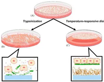
core-shell microcapsules with a porous membrane and thermo-responsive polymeric gates ...5 Figure 2.3 Schematic illustration of temperature-responsive packing materials ...6 Figure 2.4 Mechanism of cell attachment to and detachment from material surfaces...7 Figure 2.5 Temperature-responsive culture dishes. (A) During cell culture, cells
deposit extracellular matrix (ECM) molecules and form cell-to-cell junctions. (B) With typical proteolytic harvest by trypsinization, both ECM and cell-to-cell junction proteins are degraded for cell recovery. (C) In contrast, cells harvested from temperature-responsive dishes are recovered as intact sheets along with their deposited ECM, by simple
temperature reduction ...7 Figure 2.6 Tissue reconstruction using cell sheet engineering. (A) By transplanting
single cell sheets directly to host tissues, skin, cornea, periodontal
ligament, and bladder can be reconstructed. (B) Using homotypic layering of cell sheets, 3-D myocardial tissues can be created. (C) With heterotypic stratification of cell sheets, laminar structures such as liver and kidney can be fabricated. (D) Additionally, the creation of co-cultured cell sheets from dishes with dual temperature-responsive domains, also allows for the re-creation of higher-order structures such as the kidney and liver ...9 Figure 2.7 Smooth muscle cell sheets. (A) Smooth muscle cells cultured on
Figure 3.2 The schematic of graft polymerization of NIPAM...18
Figure 3.3 Layout of the cell culture insert for filtration fabric seeding...22
Figure 3.4 The schematic of the vertical wicking test ...25
Figure 4.1 Plate layout for first HEK test ...28
Figure 4.2 Plate layout for second HEK test...29
Figure 4.3 HEK growth on the control (A), glue coated well (B), 20.4 µL grafted film (C), and 30.5 µL grafted film (E); partial release and aggregation of cells after 45 minutes on 20.4 µL grafted film (D, and 30.5 µL grafted film (F)...30
Figure 4.4 Plate layout for third HEK test ...31
Figure 4.5 HEK growth on the 3 minute post-treatment plate with a 30.5 µL graft at 0 minutes (A) and 60 minutes (B) and with a 50.9 µL graft at 0 minutes (C) and 60 minutes (D); growth on the 5 minute post-treatment plate with a 30.5 µL graft at 0 minutes (E) and 60 minutes (F) and with a 50.9 µL graft at 0 minutes (G) and 60 minutes (H) ...32
Figure 4.6 Plate layout for first HFL test ...34
Figure 4.7 HFL release on grafted film edges after 0 (A), 40 (B), 55 (C), and 57 minutes (D) ...35
Figure 4.8 AFM images for the dry untreated film (A), dry plasma pretreated film (B), dry pNIPAM grafted film (C), and wet pNIPAM grafted film (D) at room temperature with a 10 µm2 scan area; phase scans of the dry (E) and wet (F) grafted films are shown at a 10 µm2 scan area ...37
Figure 4.9 Average roughness (Ra) and RMS roughness (Rq) averages shown for the 10 µm2 area scans of film samples...39
Figure 4.10 Peak-to-valley roughness (Rz) averages shown for the 10 µm2 area scans of film samples...40
Figure 4.11 SEM results of original (A, B), plasma pretreated (C, D), and grafted (E, F) film ...41
Figure 4.13 PS (A) and grafted film (B) controls after 0 minutes and staining; PS (C) and grafted film (D) after 120 minutes and staining...44 Figure 4.14 HFL release on grafted film after 55 (B), 150 (D), and 160 minutes (F);
no cell release observed on non-tissue culture treated PS plate after 55
(A), 150 (C), and 160 minutes (E) ...45 Figure 4.15 Plate layout for the proliferation test with HFLs ...46 Figure 4.16 Sequential images of an HFL cell sheet detaching from grafted film ...47 Figure 4.17 Releasing (A) and reattached cells after 3 days (B); reseeded detached
cell aggregates on day 1 (C) and day 3 (D)...48 Figure 4.18 An illustration of cell sheet detachment by different types of water
supply to (a) the grafted TCPS surface and (b) the
PIPAAm-grafted porous membrane...49 Figure 4.19 Plate layout for HEK test with fabrics ...50 Figure 4.20 FTIR spectra of the untreated, plasma pretreated, and grafted 5 µm PET
filter fabric...52 Figure 4.21 HFL growth on the untreated fabric at 10x (A) and 20x (B), on plasma
pretreated fabric at 10x (C) and 20x (D), and on grafted fabric at 10x (E, F); stained untreated (G) and grafted (H) fabrics with no cells ...54 Figure 4.22 SEM results of original (A), plasma pretreated (B), and grafted (C)
fabric ...55 Figure 4.23 Acid dye test results from untreated (A), plasma pretreated (B), and
grafted PET filtration fabric...56 Figure 4.24 Live cells seen with the viability test on grafted PET filtration fabric
seeded at a density of 20,000 cells after 1 (A), 2 (C), and 6 (E) days and seeded at a density of 40,000 cells after 1 (B), 2 (D), and 6 (F) days...58 Figure 4.25 Dead cells seen with the viability test on grafted PET filtration fabric
seeded at a density of 20,000 cells after 1 (A), 2 (C), and 6 (E) days and seeded at a density of 40,000 cells after 1 (B), 2 (D), and 6 (F) days...59 Figure 4.26 Live cells seen on grafted PET filtration fabrics after 0 (A, B), 60 (C,
Figure 4.27 Possible cell growth between the weave or in fabric pores shown with
focal point changes on same area in two parts of the fabric at 20x ...61
Figure 4.28 FTIR spectra of the cotton fabrics ...64
Figure 4.29 FTIR spectra of the nylon fabrics ...65
Figure 4.30 FTIR spectra of the polyester fabrics...66
Figure 4.31 Average percent of total wetting after 5 minutes with cool water (blue) and warm water (purple) ...68
Figure 4.32 Average percent of total wetting after 15 minutes with cool water (blue) and warm water (purple) ...69
Figure 4.33 Average percent of total wetting after 30 minutes with cool water (blue) and warm water (purple) ...70
Figure 4.34 Average percent of total wetting after 5 minutes with cool water (blue) and warm water (purple) ...71
Figure 4.35 Average percent of total wetting after 15 minutes with cool water (blue) and warm water (purple) ...72
Figure 4.36 Average percent of total wetting after 30 minutes with cool water (blue) and warm water (purple) ...73
Figure 4.37 Dye test results on untreated (A), untreated and washed (B), plasma pretreated (C), plasma pretreated and washed (D), grafted (E), coat-grafted and washed (F), spray-coat-grafted (G), and spray-coat-grafted and washed (H) cotton fabrics ...74
1. INTRODUCTION
Responsive polymers exhibit functional changes in response to a stimulus giving them dual and reversible properties. These polymers have received much attention for many applications including biotechnology and smart textiles. Particularly attractive responsive polymers are those stimulated by temperature. They are easy to control and allow for careful modulation of the property changes of the polymer. Poly
(N-isopropylacrylamide) (pNIPAM) is a thermally responsive polymer that displays a phase change at 32oC, which is between room and body temperatures.[1] This transition
temperature allows it to be useful for biological applications such as drug delivery, bioseparation, biosensors, gene delivery, and cell sheet engineering.[5] Above 32oC in water, the polymer becomes dehydrated and hydrophobic allowing cell adhesion; when the temperature is dropped below 32oC, the polymer chains rapidly hydrate and cells detach from the surface.[37] The potential for releasing cell sheets with intact junctions is
important for the future of tissue engineering as it does not introduce any of the problems with current approaches such as compliance mismatch, the inflammatory response, and the inability to repair large areas of tissue.
This work evaluates atmospheric plasma grafting of pNIPAM on polyester film and optimization of treatment parameters with cell culture studies intended as a model for cell attachment/detachment on polyester filtration fabric. It also examines two methods of pNIPAM grafting on woven cotton, nylon, and polyester fabrics through surface
2. LITERATURE REVIEW
2.1. Thermoresponsive Polymers
“Smart” polymers are those that demonstrate reversible sharp property changes in response to environmental cues such as pH, electric field, light, and temperature.
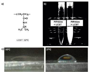
Figure 2.1: Structure and properties of thermoresponsive PIPAAm in solution and on surfaces. (a) Structural formula for PIPAAm. (b) Thermoresponsive soluble/insoluble changes for PIPAAm in aqueous solution. (c) Temperature-dependent wettability changes
for PIPAAm-grafted surfaces at 10 and 37 °C.[2]
The LCST of pNIPAM is significant because it falls between room and body temperatures making it beneficial for medical applications.
2.2. Applications of pNIPAM
Grafting pNIPAM onto surfaces such as textiles or plastics endows the new material with the same thermoresponsiveness of the polymer. This grafting allows for greater potential applications and usable forms. The proximity of the LCST to body and cell culture temperatures and its responsive nature make it valuable for use in
biotechnology and medical applications such as drug delivery, chromatography, tissue engineering, and cell sheet engineering.[2,5]
For drug delivery, it has been used to make core-shell microcapsules with thermo-responsive gates as shown in Figure 2.2, drug loaded thermo-thermo-responsive micelles or in water-diffusion controlled release hydrogels.[7- 9]
core-For chromatography, it has been used to make modified column matrices with grafted beads.[10,11] Figure 2.3 shows how the thermoresponsive beads respond to temperature.
Figure 2.4: Mechanism of cell attachment to and detachment from material surfaces.[13] This behavior is advantageous because it eliminates the need for enzymatic or mechanical detachment of cells allowing them to retain their morphology and function as shown in Figure 2.5.
Figure 2.5: Temperature-responsive culture dishes. (A) During cell culture, cells deposit extracellular matrix (ECM) molecules and form cell-to-cell junctions. (B) With typical
proteolytic harvest by trypsinization, both ECM and cell-to-cell junction proteins are degraded for cell recovery. (C) In contrast, cells harvested from temperature-responsive
It has been found that enzymatic and mechanical detachment can disrupt the cell membrane and cause a change in cellular activity.[15]
As mentioned above, pNIPAM grafted surfaces have already been used extensively for cell culturing being used with urothelial, vascular smooth muscle, retinal, and lung cells to list a few.[16-19] This has led it to be looked at for tissue engineering and more specifically cell sheet engineering use. Traditional methods for tissue engineering are based on isolated cell suspensions or biodegradable scaffolds.[6] These two methods have shown limited success and improvement of them has been slower than expected leaving room open for other options. Okano’s group recently identified cell sheet engineering as another option.[6] This type of engineering is advantageous because it yields cell sheets that retain their native extracellular matrix, which is responsible for the intrinsic
Figure 2.6: Tissue reconstruction using cell sheet engineering. (A) By transplanting single cell sheets directly to host tissues, skin, cornea, periodontal ligament, and bladder can be reconstructed. (B) Using homotypic layering of cell sheets, 3-D myocardial tissues can be
created. (C) With heterotypic stratification of cell sheets, laminar structures such as liver and kidney can be fabricated. (D) Additionally, the creation of co-cultured cell sheets from dishes with dual temperature-responsive domains, also allows for the re-creation of
higher-order structures such as the kidney and liver.[6]
Figure 2.7: Smooth muscle cell sheets. (A) Smooth muscle cells cultured on temperature-responsive dishes can be harvested as intact sheets by simple temperature reduction. (B) Two or (C) five smooth muscle cell sheets can be layered in vitro. (D) Five-layer smooth muscle cell constructs can be transplanted subcutaneously and adhere after 5 min due to the presence of deposited extracellular matrix. Note: In panel (D), sutures are used only to
mark the borders of the transplanted constructs.[6]
Advantages to using pNIPAM coated surfaces in cell sheet engineering include their ability to grow co-culture systems, to be modified with peptide sequences, and to form micropatterns.[2,6]
2.3. Grafting Methods
2.3.1. Traditional Grafting Methods
Most of the recent work with pNIPAM grafted surfaces for tissue engineering purposes has been by Okano et al. and Ratner et al. Okano has used chemical and electron beam irradiation grafting.[20-23] Although these methods have been very successful and well characterized, chemical grafting requires the use of numerous toxic reagents and gases with lengthy preparation times; and electron beam irradiation introduces radiation into the process. Overall, these two methods lead to a lengthy, expensive, and potentially
hazardous preparation of grafted surfaces.
Ratner has used vapor-phase deposition of pNIPAM by plasma polymerization.[1] This process is useful because it is one-step and does not require the use of solvents making it safe and environmentally friendly. Plasma polymerization itself also has many advantages including the creation of uniform, adhesive, and pinhole-free grafts.[1] Like Okano, they have extensively characterized the resulting pNIPAM graft. However, the vapor-phase plasma polymerization requires the use of vacuum, high temperatures, and low chamber pressure. Overall, this method is still expensive and does not allow for the production of large grafted surfaces.
2.3.2. Atmospheric Plasma Grafting
Plasma is an ionized gas consisting of electrons, ions, radicals, atoms, and molecules created with electrical or thermal stimulation.[32,35] Plasma treatment has
already been used extensively for surface modification by bombarding the surface with the species created from the ionized gas and with the creation of free radicals on the
without changing the bulk material properties.[33,35] Figure 2.8 shows how plasma treatment can be used to modify surfaces through crosslinking, etching, grafting, and functionalization.
Figure 2.8: Schematic of the reaction mechanisms of plasma surface modifications.[33] Many different gases including argon, helium, oxygen, nitrogen, and fluorine can be utilized with plasma.[35] The two gases chosen for this study were helium as the seed gas and oxygen as the treatment gas. Helium is an inert gas that is highly stable and produces a uniform plasma. Oxygen creates functional groups at the surface and aids in crosslinking and sterilization.[35]
graft that does not require extensive chemical use or expensive equipment. It is also effective in producing a sterile substrate for cell culture.[33] Atmospheric plasma treatment can be performed at room temperature and pressure without extra chemical reagents and can accommodate the processing of large surface area and continuous production lines. The large scale capabilities of this method will enable production of a fabric substrate that can be used to grow significant amounts of cells. Since the fabric is pliable, it can be treated and then packed into a smaller space with large cell growth capabilities per area. By being able to graft onto fabrics, we will be able to use them for scaffolds in bioreactors and create large cell sheets.
2.4. Previous Work with pNIPAM Grafted Surfaces
PNIPAM grafted surfaces have been extensively characterized and studied for use with cell culture. Successful cell sheet engineering has been achieved with cardiac myocytes,[40-43] keratinocytes,[44] lung cells,[19] urothelial cells,[16] periodontal ligament cells,[45] and tracheal epithelial cells.[46]
Since 1990, Okano et al. have evaluated pNIPAM grafted surfaces by testing cell proliferation and detachment with bovine aortic endothelial cells and rat hepatocytes on tissue culture polystyrene (TCPS) plates and PET membranes.[4,12,13,23,36-38] Okano et al. have also studied the mechanism of cellular activity with grafted surfaces through
electron spectroscopy for chemical analysis (ESCA), and atomic force microscopy (AFM) to examine the thermoresponsiveness, graft thickness, and surface chemistry and
morphology.[4,20,23] It was found that electron beam irradiation successfully grafted pNIPAM onto porous cell culture membranes making them more smooth than the
ungrafted membrane.[4] It was also found that, with electron beam irradiation grafting, the thermoresponsiveness of the polymer and cell attachment and detachment is affected by the graft thickness.[23] The thickness is thought to affect the polymer chain mobility and interactions. The graft thickness that was most successful in cell culture studies was 8-23 nm.[23] The thin grafts have a lower chain mobility below the LCST which promotes aggregation and enhances dehydration; however, the thicker grafts have increased hydration even below the LCST which does not allow for cell adhesion.[23]
ToF-SIMS.[15,47] It was found that cell detachment using pNIPAM grafted surfaces is less harmful to extracellular matrix proteins than enzymatic and mechanical processes.[15] Although this type of cell detachment results in an intact extracellular matrix, some of the extracellular matrix proteins are left on the surface after release.[47]
Other successful cell attachment/detachment has been demonstrated with corneal endothelial cell sheets[48] and neural cells;[49] however, a minimal amount of research has been published on the tissue engineering potential of pNIPAM grafted surfaces besides the work by Ratner and Okano. Most other cell culture studies utilize pNIPAM in copolymer systems with polymers such as gelatin or acrylic acid.
Preliminary work characterizing pNIPAM grafted on PS plates and nylon film using a novel atmospheric plasma method demonstrated successful grafting of pNIPAM and its retention of thermoresponsiveness. This was confirmed through FTIR, contact angle measurements, and cell attachment and detachment with Hep G2 cells.[24] The effects of grafting parameters such as plasma pre- and post-treatment times and monomer solution volume were examined as well.
The application of responsive polymers has also led to interest in the development of smart textiles. In the textiles industry, pNIPAM has been studied mostly with
3. MATERIALS AND METHODS
3.1. NIPAM Solution Preparation
N-isopropylacrylamide (NIPAM, 99%) was purchased from Acros Organics (Hampton, NH) and was recrystallized for further purification using hexane (95%) from Acros Organic (Hampton, NH). To recrystallize the NIPAM, 10.33 g was added to 125 mL of hexane. The mixture was dissolved on a hot plate while stirring. The solution was allowed to cool and recrystallize before being filtered to remove impurities and washed with hexane then left to dry in a fume hood. The NIPAM monomer solution was a 45% solution with 2-propanol. The 2-propanol used was purchased from Sigma-Aldrich (St. Louis, MO).
3.2. pNIPAM Grafting
3.2.1. Atmospheric Plasma Parameters
The grafting was performed in an atmospheric glow discharge device (APGD) plasma treatment system.[25] A schematic of the apparatus is shown in Figure 3.1. The atmospheric plasma was generated using 99% He/1% O2 gas at flow rates of 10 and 0.14
Figure 3.1: Schematic of the atmospheric pressure plasma device.[25] 3.2.2. Polystyrene Plate and Polyester Film and Filter Fabric Grafting Method
solution. The volume of monomer solution used is shown in Table 3.1 according to the type of plate used. The solution was spread evenly with gentle agitation by hand. After coating, the polymer was grafted onto the surface of the samples with post-treatment in the APGD. The samples were then vigorously washed with cooled distilled water to remove any unpolymerized NIPAM and left to dry. The samples prepared for cell culture studies were washed with sterile water and dried in a sterile hood. Figure 3.2 shows a schematic of the pNIPAM grafting process.
Figure 3.2: The schematic of graft polymerization of NIPAM.[24]
Table 3.1: Volumes of monomer solution used based on plate type.
Volume Tested (µµµµL)
Plate Type
Well Area
(cm2) 5.14 µl/cm2 10.3 µl/cm2 15.4 µl/cm2 20.6 µl/cm2 25.7 µl/cm2
6-well 9.72 50 ul 100 ul 150 ul 200 ul 250 ul
24-well 1.98 10.2 ul 20.4 ul 30.5 ul 40.8 ul 50.9 ul
60 mm 28.27 145.3 ul 291.2 ul 435.4 ul 582.4 ul 726.5 ul
3.2.3. Fabric Grafting Method
Woven cotton (greige, 122 g/m2), nylon (spun Dupont Type 200, 124 g/m2), and polyester (batiste, 72 g/m2) fabrics from Testfabrics, Inc. (West Pittston, PA) were
provided in the lab. Three sets of samples were made with each of the fabrics according to Table 3.2.
Table 3.2: Grafting methods for the coated and sprayed fabrics.
Fabric Set Monomer Solution Application Method Amount of Solution Applied Plasma Pretreatment Time (min) Plasma Post-treatment Time (min) Washing Method Drying Method
Coated Dipped
completely submerged (excess padded
off) 3 5
agitated in cool distilled
water oven
Sprayed 1 Sprayed w/airbrush until entire surface visibly
wet 3 5
agitated in cool distilled
water oven
Sprayed 2 Sprayed w/spray bottle until entire surface visibly
wet 3 5
agitated in cool distilled
water oven
3.3. Surface Characterization 3.3.1. Contact Angle
The water contact angles of the pNIPAM-grafted PET film and filter fabric samples were measured in air at 25°C and 40°C using the sessile drop method with a goniometer
warm tests. Deionized (DI) water (8 µL) was dropped on the samples using a syringe. The contact angle was read 10 seconds after the water drop contacted the sample.
3.3.2. Atomic Force Microscopy
The surface topography of the PET films was examined with an atomic force microscope (JEOL JSPM-5200) under tapping mode in dry and wet phase (DI water). The original and plasma pretreated films were scanned in the dry phase at room temperature
(24°C), and the grafted film was characterized in the dry phase (24°C) and wet phase at
room temperature and 37°C. Measurements were carried out with a BS-Multi 75Al silicon
probe at varying scan areas. The thickness of the graft was determined with the Digital Instruments D3000 under tapping mode in dry phase at room temperature with a BS-Multi 75Al silicon probe. An xy- and x-scan were done to confirm results. The sample for this test was a templated grafted 60 mm PS plate. The template was created by placing a piece of static cling film to the bottom of the plate prior to plasma treatment. The film was peeled off to allow a vertical distance to be recorded between the grafted and ungrafted portions.
3.3.3. Scanning Electron Microscopy
The surface topography of the PET film and filter fabric was examined with a scanning electron microscope (Hitachi S-3200N) under vacuum at room temperature at 5 kV. The samples were gold plate coated by sputtering for 180 seconds with argon. 3.3.4. Fourier Transform Infrared Spectroscopy
conjunction with the Avatar Omni Sampler, which is an attenuated total reflection (ATR)
accessory with a 45° KRS-5 crystal. The spectra were collected at 4 cm-1 resolution with
an FTIR microscopic spectrometer over 64 scans at room temperature. 3.4. Cell Culture Studies
3.4.1 Human Epidermal Keratinocyte Studies
Human epidermal keratinocytes (HEKs) were cultured in keratinocyte basal medium (KBM-2) (Cambrex, East Rutherford, NJ) supplemented with 0.1 ng/mL human epidermal growth factor, 5 mg/mL insulin, 0.4% bovine pituitary extract, 0.1%
hydrocortisone, 0.1% transferring, 0.1% epinephrine, and 50 mg/mL gentamicin/50 ng/mL amphotericin-B (Single Quots, Cambrex). The cells were seeded at a density of
approximately 20,000 cells/well in 1 mL of media in treated 24-well PS plates. The cells
were incubated at 37°C in a humidified atmosphere with 5% CO2. A media change was
performed on day 2 and day 5 if the cells had not reached at least 75% confluency at that time. The cells were removed from the incubator and allowed to remain at room
temperature (25°C) for 1.5 hours.
3.4.2 Human Lung Fibroblast Studies
grafted fabric glued to the underside in a 6-well PS plate. Figure 3.3 shows a layout of the insert for the fabric study.
Figure 3.3: Layout of the cell culture insert for filtration fabric seeding. The inserts were left inverted for the cells to attach for 2-4 hours and then turned over to
have 1.5 mL of media added. The cells were incubated at 37°C in a humidified
atmosphere with 5% CO2. A media change was performed on day 2, and the cells were
photographed on day 4. For better visualization, the cells on the fabric samples were stained with Coommassie Blue for 1-2 minutes then rinsed with phosphate buffered saline (PBS) several times. After removal from the incubator, the plates were allowed to reach room temperature (25°C) and checked periodically over a period of one hour.
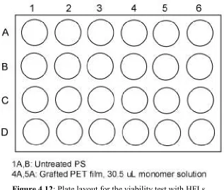
3.4.3. Viability Test
The test wells were a non-tissue culture treated well and a grafted PET film well. These cells were left out at room temperature for 2 hours to allow for release, and then Trypan Blue (1 mL) was added and allowed to sit for 5 minutes. The wells were then carefully washed with PBS. The viable and dead cells were visually noted and photographed in the wells.
3.4.4. Proliferation Test of Released Cells
The proliferation of the releasing HFLs was evaluated by allowing the cells to grow to confluency on grafted film in a 24-well plate. The cells were seeded at 250,000 cells per well in 1 mL of growth medium. After being allowed to release at room temperature for 60 minutes, the cell aggregates and medium were transferred with a pipette to a new non-tissue culture treated well. The cells were then incubated for 3 days and observed. 3.4.5. Human Hepatocellular Carcinoma Cell Studies
Human hepatocellular carcinoma (Hep G2) cells were purchased from ATCC (Mannasas, VA) and cultured in Eagle’s minimum essential medium (EMEM 1X) (Cellgro, Herndon, VA) supplemented with 1 mM sodium pyruvate (Cellgro) , 0.1 mM MEM non-essential amino acids (Cellgro), 10% fetal bovine serum (FBS) (Cambrex, East Rutherford, NJ) , pen/strep (Cellgro), and 2 mM L-glutamine (Cellgro). For the fabric samples, the cells were seeded at a density of approximately 20,000 cells/well in 2 mL of
media in a 6-well PS plate. The fabric was seeded with 100 µL of the cell suspension and
left to attach for 1 hour before having 2 mL of media added. The cells were incubated at 37°C in a humidified atmosphere with 5% CO2. No media change was performed, and the
3.4.6. Live/Dead Viability Assay
A Live/Dead Viability Assay kit was purchased from Molecular Probes (Eugene,
OR). Small pieces of grafted PET filtration fabric (5 µm pore size) were put in a non-tissue culture treated 6-well plate. Three wells were seeded at a density of 20,000 cells in
50 µL of medium, and three wells were seeded at a density of 40,000 cells in 100 µL of
medium. The cells were incubated and allowed to adhere to the fabric for 1 hour after which 2 mL of growth medium was added. The cells were grown for 1, 2, and 6 days. After allowing the cells to grow for the specified period of time, the fabric pieces were
inverted and washed twice with PBS. A 4 µM ethidium homodimer-1 and 2 µM calcein
AM solution was prepared, and 2 mL was added to the wells and incubated for 10 minutes at room temperature. The fabric was viewed on an inverted fluorescent microscope (Leica DMIL) with a standard fluorescein bandpass filter for the live cells (Chroma 41001) and a standard rhodomine bandpass filter for the dead cells (Chroma 41002).
3.5. Fabric Characterization 3.5.1. Vertical Wicking
Figure 3.4: The schematic of the vertical wicking test.
The tests were performed with room temperature water (20oC) and water warmed with a hot plate (50oC). The height to which the water was taken up along the strip was measured at 5, 15, and 30 minute intervals.
3.5.2. Fourier Transform Infrared Spectroscopy
The surface chemistry of the grafted nylon, polyester, and cotton fabrics was examined with Fourier transform infrared spectroscopy (FTIR). The Nexus 470 FTIR spectrometer was used in conjunction with the Avatar Omni Sampler, which is an
attenuated total reflection (ATR) accessory with a 45° KRS-5 crystal. The spectra were
3.5.3. Acid Dye Test
Dystar Acid Blue 264 dye was used to examine the uniformity of the graft on the polyester and cotton fabrics. To make a dye solution of 3 g/L, 0.6 g of dye was added to 200 mL of water and 2 drops of acetic acid. The solution was stirred with the fabric samples for 15 minutes and then rinsed vigorously and dried in an oven.
3.5.4. Washfastness
The washfastness of the grafted pNIPAM on the cotton, nylon, and polyester fabrics was examined according to a modified version of AATCC Test Method 61-1993. The samples, cut to no specific size, were conditioned and weighed prior to the grafting procedure and after the grafting procedure. The edges of the samples were sealed with
4. RESULTS AND DISCUSSION
4.1. Optimization of Plasma Treatment Times and Monomer Solution Volume on Grafted Polyester Film
Polyester film was chosen as a preliminary surface for testing due to the ease of grafting and potential for use as a model for surface characterization to predict effects on grafted polyester filtration fabric. Based on previous work, the plasma pretreatment time was set at 3 minutes. Although previous cell culture tests were successful with plasma post-treatment times of 3, 5, and 10 minutes, longer plasma exposure times with polyester film result in increased etching and similar surface activation as shorter times.[24,26] Thus, the decision was made to try to minimize the plasma exposure time. Using data from
previous studies on the effect of monomer solution volume on graft yield, 50 and 100 µL monomer solution volumes (in a six-well plate) were chosen.[24] Plasma post-treatment times were 0.5 and 2 minutes. Since the ultimate goal is to produce surfaces for efficient cell sheet engineering, the parameters were optimized through cell culture and comparison to controls.
Figure 4.1: Plate layout for first HEK test.
Two wells were seeded in a tissue culture treated 24-well plate as controls. After 7 days, the controls reached 100% confluency. Both plates had spotty growth in all columns with about 50% confluency. The cells looked stressed and stretched in some wells on both plates. After 1 hour at room temperature, there was no complete cell detachment observed,
but column 6 (30.5 µL monomer solution) had the most partial detachment. The decreased
To address these problems, the washing was increased, and the toxicity of the glue was tested. The post-treatment time was increased to 5 minutes, and the lower monomer solution volume was discarded. Figure 4.2 show the plate layout.
Figure 4.2: Plate layout for second HEK test.
Two wells were seeded in a tissue culture treated 24-well plate as controls. After 4 days, the controls reached 100% confluency. The test wells were all about 60% confluent; and although growth on the glue was minimal, it did not hinder growth in the well. After 90 minutes at room temperature, there was no complete cell detachment observed, but column
6 (30.5 µL monomer solution) had the most partial detachment and the best growth.
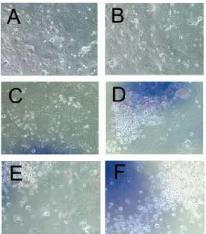
Figure 4.3: HEK growth on the control (A), glue coated well (B), 20.4 µL grafted film (C), and 30.5 µL grafted film (E); partial release and aggregation of cells after 45 minutes on
20.4 µL grafted film (D, and 30.5 µL grafted film (F).
The increased cell growth with the second test encouraged testing of a slightly higher monomer solution volume and further testing of the plasma post-treatment time. One plate was made with a 3 minute post-treatment time, and the other plate was made with a 5 minute post-treatment time. Figure 4.4 shows the plate layout.
Figure 4.4: Plate layout for third HEK test.
After 4 days, the cells were observed and left at room temperature for 60 minutes to induce cell release. The 3 minute post-treatment plate had good growth with 65-90% confluency. The 5 minute post-treatment plate also had good growth with 70-85% confluency.
Figure 4.5: HEK growth on the 3 minute post-treatment plate with a 30.5 µL graft at 0 minutes (A) and 60 minutes (B) and with a 50.9 µL graft at 0 minutes (C) and 60 minutes (D); growth on the 5 minute post-treatment plate with a 30.5 µL graft at 0 minutes (E) and
grafting parameters for cell growth and detachment are 3 minute plasma pretreatment, 5
minute plasma post-treatment, and 30.5 µL of monomer solution in a 24-well plate.
4.2. Characterization of Optimally Grafted Polyester Film
With the optimal grafting parameters found, the films needed to be characterized to determine the uniformity, surface morphology, and efficiency of the graft. Several different test methods were chosen to characterize the grafted polyester film. All samples
prepared from this point on were plasma pretreated for 3 minutes, coated with 15.4 µL/cm2 NIPAM monomer solution, and plasma grafted for 5 minutes.
4.2.1. Effects of Temperature on Surface Wettability
Contact angle testing is a quick way to determine the changes in wettability of the treated surface and confirm the presence of the graft. A summary of the contact angle results for the PET films is shown in Table 4.1.
Table 4.1: Average contact angle results for PET films in degrees.
Temperature Original Plasma Pretreated Grafted Warm (40°°°°C) 73.8 ± 1.9 61.4 ± 7.7 77.4 ± 6.6
Cool (25°°°°C) 69.0 ± 5.5 49.1 ± 2.5 64.5 ± 3.6
The contact angles on the grafted film change from 77.4 ± 6.6° at 40°C to 64.5 ± 3.5° at
25°C. It is also interesting that the contact angles changed with the temperature changes on the original and pretreated samples; however, they were not as great as the grafted film.
The significantly higher contact angle at 40°C on the grafted film shows that the surface
4.2.2. Cell Growth and Detachment with HFLs
To make sure the grafted surfaces were viable for use with different types of cells, grafted films were tested with human lung fibroblasts. The first optimal cell culture test was done with HFLs on a non-tissue culture treated 24-well plate. Figure 4.6 shows the plate layout.
Figure 4.6: Plate layout for first HFL test.
These results confirm both the sufficient growth on the hydrophobic surface and partial sheet release of HFLs on the hydrophilic surface of the grafted films. It also demonstrates the ability of the grafted films to be used with various cell types.
Figure 4.7: HFL release on grafted film edges after 0 (A), 40 (B), 55 (C), and 57 minutes (D).
4.2.3. Surface Roughness
Atomic force microscopy (AFM) allows a better view at the atomic level of the surfaces and an idea of how the surface roughness changes. A liquid cell with controlled temperature was used to examine the changes in surface topography and surface
treatment induces significant changes in the roughness of a polyester film substrate due to etching.[26] With these two things in mind, we can account for the changes in the
appearances of the surface with each treatment.
The results from the dry and wet scans are shown below in Figure 4.8. Plasma pre-treatment has an obvious effect on the surface roughness as indicated by Figure 4.8 A and B. The plasma pretreated film shown in B showed a reduction in the mean-square
Figure 4.8: AFM images for the dry untreated film (A), dry plasma pretreated film (B), dry pNIPAM grafted film (C), and wet pNIPAM grafted film (D) at room temperature with
When placed in water at room temperature, the surface becomes significantly rougher and more variable. At 37ºC, the surface shows a large increase in roughness. Phase images of the grafted polymer reveal a relatively uniform surface for the dry graft, and an orange peel type phase variation on the wet graft surface. The nanometer-size dots in the wet phase image (F) may be the result of changes in the polymer crosslink density over the
surface.[5,27] The surface transformation in the hydrated state leads to a change in average
roughness (Ra) from 4.72 ± 0.71 nm (dry) to 5.90 ± 1.51 nm (wet, 24o) and 12.24 ± 5.32
nm (wet, 37o). This can be seen in Figure 4.9. The RMS roughness also increased from
AFM Average Roughnesses 0.00 5.00 10.00 15.00 20.00 25.00 30.00 35.00 40.00 45.00 50.00
original (dry) plasma pretreated (dry) pNIPAM grafted (dry) pNIPAM grafted (wet, 24C) pNIPAM grafted (wet, 37C) Sample R o u g h n e s s ( n m ) Ra Rq
Figure 4.9: Average roughness (Ra) and RMS roughness (Rq) averages shown for the 10 µm2 area scans of film samples.
AFM Average Peak-to-Valley Roughness 0.00 200.00 400.00 600.00 800.00 1000.00 1200.00 1400.00 1600.00
original (dry) plasma pretreated (dry) pNIPAM grafted (dry) pNIPAM grafted (wet, 24C) pNIPAM grafted (wet, 37C) Sample P e a k -t o -V a ll y R o u g h n e s s ( n m )
Figure 4.10: Peak-to-valley roughness (Rz) averages shown for the 10 µm2 area scans of film samples.
4.2.4. Surface Morphology
Figure 4.11: SEM results of original (A, B), plasma pretreated (C, D), and grafted (E, F) film.
grafted polymer is apparent on the films as shown in Figure 4.11 E and F. The graft fills in the natural cavities on the original film. This finding is also consistent with the results of Kwon et al. and confirms the presence of the graft.[4]
4.2.5. Graft Thickness
The thickness of the graft was previously thought to be very small and immeasurable through weight and graft yield. AFM was performed on a grafted and templated 60 mm PS plate because it was too difficult to resolve an adequate edge between the ungrafted and grafted areas due to the irregularities of the original PET film on that scale. The results from the thickness test are shown in Table 4.2. The maximum and minimum thicknesses were taken due to the discretionary component of the measuring software. The averages for the sample gave a good estimate of the thickness and confirm the thin graft suspected on the samples. From this data, it can be said with confidence that the graft is between 30 and 100 nm. Although the found thickness is considerably higher than was found by Okano et al. to allow for cell adhesion and proliferation, the graft thickness does not seem to have the same effects when using atmospheric plasma polymerization.
Table 4.2: Average maximum and minimum graft thicknesses in dry phase.
Average Max Thickness (nm) Average Min Thickness (nm)
Dry 69.8 ± 22.8 52.0 ± 22.0
4.2.6. Cell Viability
incubator environment for detachment. The viability test was done with HFLs on a non-tissue culture treated 24-well plate. Figure 4.12 shows the plate layout.
Figure 4.12: Plate layout for the viability test with HFLs.
After 4 days, the cells were removed from the incubator and kept at room temperature to observe cell detachment and viability. The two wells (1A and 4A) were immediately stained to use as controls of initial cell viability. No dead cells were visible in these wells. In the two test wells (1B and 5A), the stain was added after 120 minutes at room
Figure 4.13: PS (A) and grafted film (B) controls after 0 minutes and staining; PS (C) and grafted film (D) after 120 minutes and staining.
Figure 4.14: HFL release on grafted film after 55 (B), 150 (D), and 160 minutes (F); no cell release observed on non-tissue culture treated PS plate after 55 (A), 150 (C), and 160
minutes (E). 4.2.7. Cell Proliferation after Release
Figure 4.15: Plate layout for the proliferation test with HFLs.
After two days, the cells were observed and left at room temperature for 60 minutes to induce cell release. The control wells were all 100% confluent. The cells on the grafted film were about 60% confluent and had cell ball aggregates form prior to release. These were thought to be due to the increased number of cells used for seeding.
view. The contraction and aggregation of the detaching cells is similar to what was seen by Kwon et al. and is due to cell-cell connections.[4]
Figure 4.16: Sequential images of an HFL cell sheet detaching from grafted film. After allowing the cells to detach for 45 minutes, a portion of the released cells and medium were pipetted into a new well. After 3 days, the cells were checked for
and had grown to at least 50% confluency. The cell sheets seen rolled up above left in their original wells with medium also laid back down on the plate and displayed new growth. The results of the regrowth test are shown in Figure 4.17. This observation demonstrates the reversible nature of the graft as the cells reattached after the pNIPAM was warmed back up to 37oC. The regrowth of released cells and reversibility of graft properties corresponds with the findings of Kwon et al. confirming the health and functionality of the detached cells.[4]
Figure 4.17: Releasing (A) and reattached cells after 3 days (B); reseeded detached cell aggregates on day 1 (C) and day 3 (D).
4.3. Characterization of Optimally Grafted Polyester Fabric
due to the defined and uniform porosity. Kwon et al. have found that an increase in the hydration of the polymer chains can lead to faster cell sheet detachment by allowing greater water movement between the cells and substrate.[4] This principle is shown in Figure 4.18.
Figure 4.18: An illustration of cell sheet detachment by different types of water supply to (a) the PIPAAm-grafted TCPS surface and (b) the PIPAAm-grafted porous membrane.[4] Their work with a microporous polyester membrane showed a significant decrease in detachment time when compared with PS plates.[4] However, no previous work has been done with pNIPAM grafted fabrics, and its success with cell growth and detachment holds possibilities for currently unavailable large-scale cell growth and cell sheet engineering. 4.3.1. Cell Growth and Detachment with HEKs
Figure 4.19: Plate layout for HEK test with fabrics.
After 4 days, the cells were observed and left at room temperature for 60 minutes to induce cell release. The fabric could only be seen with an inverted microscope due to accessibility requiring observation of the cells through the pores. As a result, it was very difficult to see if any cells were growing on the fabric. However, cells were seen on the bottom of the
wells with the 21 µm fabric, which means they were able to fall through the pores. The
test was inconclusive for cell growth and release but did lead to the decision to use the 5
4.3.2. Effects of Temperature on Surface Wettability
Contact angle testing is a quick way to determine the changes in wettability of the treated surface and confirm the presence of the graft. A summary of the contact angle results for the PET fabric is shown in Table 4.3.
Table 4.3: Average contact angle results for PET fabric in degrees.
Temperature Original Plasma Pretreated Grafted
Warm (40°°°°C) 50.0 55.0 54.7 ± 5.3
Cool (25°°°°C) NA NA 35.5 ± 0.1
The contact angle changes on the grafted fabrics were dramatic. They demonstrated a
change from 54.7° at 40°C to 35.5° at 25°C. The original and pretreated fabrics were only
tested at warm temperature as no change was expected. In previous work in our
laboratory, it was found that the wettability of plasma treated polyester samples increased, and the contact angle decreased due to the extra –OH groups on the surface after treatment with oxygen gas plasma.[4] However, it was later found that the fabric was treated with an anti-static chemical during manufacturing making it more hydrophilic than normal
polyester. Regardless, these results confirm the grafting of pNIPAM onto the surfaces and its thermoresponsiveness.
4.3.3. Surface Chemistry
cm-1 (secondary amide N-H stretching), 1650 cm-1 (secondary amide C=O stretching), 2970 cm-1 (-CH3 asymmetric stretching), and 3300 cm-1 (secondary amide N-H
stretching).1,3 The test was done to further confirm the presence of the graft and give an indication of the amount of pNIPAM being grafted. The results found are shown in Figure 4.20 and do not show any of the characteristic peaks normally found from pNIPAM. Since
the crystal on the spectrometer penetrates to a depth of 0.5 µm, it is likely that it penetrated through the thin coating and is only showing the spectra of the polyester.
Figure 4.20: FTIR spectra of the untreated, plasma pretreated, and grafted 5 µm PET filter fabric.
4.3.4. Cell Growth and Detachment with HFLs
and grafted fabric samples were tested. The cells were checked four days after seeding and kept at room temperature to observe cell detachment. Once again, the cells were difficult to distinguish, so Coomassie Blue was used to stain the cells prior to viewing. The cells were approximately 90% confluent on the surrounding insert, but it is difficult to
Figure 4.21: HFL growth on the untreated fabric at 10x (A) and 20x (B), on plasma pretreated fabric at 10x (C) and 20x (D), and on grafted fabric at 10x (E, F); stained
4.3.5. Surface Morphology
Scanning electron microscopy was used to examine the plasma treated and grafted surfaces and to characterize the uniformity of the grafted pNIPAM. The SEM images are shown in Figure 4.22. The grafted polymer was not readily apparent on the surfaces of the fabrics, although the grafted fabric filaments do appear smoother as though the pNIPAM filled in the surface blemishes. However, as suspected, the thickness of the graft was insufficient to be detected using SEM.
4.3.6. Graft Uniformity
Although the contact angle measurements on the grafted fabric demonstrated the thermoresponsiveness of the pNIPAM, further confirmation of the uniformity of the graft was necessary to ensure efficiency of the plasma treatment. A simple dye test using an acid dye, which is known to color the amino end groups of nylons, was used since pNIPAM is an amide.[29] A piece of untreated, plasma pretreated, and grafted fabric was tested. The results are shown in Figure 4.23.
Figure 4.23: Acid dye test results from untreated (A), plasma pretreated (B), and grafted PET filtration fabric.
The blue coloring on the grafted fabric was clearly visible and was not seen on the untreated and plasma pretreated fabrics. However, the dye does look darker in some spots possibly indicating a thicker graft in those areas. This test confirmed that the pNIPAM was successfully grafted to the filtration fabric in a fairly uniform manner with some patchy areas.
4.3.7. Cell Growth, Detachment, and Viability with Hep G2 Cells
Because of previous problems viewing the cells, a fluorescent nuclear stain was used to view cell growth and detachment; and a fluorescent assay was performed to confirm the viability of the cells on the fabric. The fabric fluoresces naturally but not enough to present a problem when viewing the cells.
Figure 4.24: Live cells seen with the viability test on grafted PET filtration fabric seeded at a density of 20,000 cells after 1 (A), 2 (C), and 6 (E) days and seeded at a density of
Figure 4.25: Dead cells seen with the viability test on grafted PET filtration fabric seeded at a density of 20,000 cells after 1 (A), 2 (C), and 6 (E) days and seeded at a density of
40,000 cells after 1 (B), 2 (D), and 6 (F) days.
For the cell growth and detachment test, the cells were observed and left at room temperature for 60 minutes to induce cell release after growing for 4 days. Two fabric samples were tested. The cells grew to about 50% confluency after 4 days on both
was visible. To aid in detachment, the samples were placed in a refrigerator and cooled further for 30 minutes. Even after 90 minutes, the cells remained attached to the fabric. These results were very unexpected since Kwon et al. noted a 50% reduction in release time when the cells were grown on a porous membrane compared to the PS plates.[4] The results of the detachment test are shown in Figure 4.26.
Even with the fluorescent stain, clear visualization of the cells on the fabric was difficult. The cells clearly proliferated well on the grafted fabric; but after no detachment was observed after cooling for 90 minutes, the cells were examined further. A closer look at the cells revealed possible growth in the pores or between the twill weave of the fabric shown in Figure 4.27. The circled areas highlight cells that come into or out of focus with the change in focal point on the fabric. This suggests cells are growing in both focal planes.
Figure 4.27: Possible cell growth between the weave or in fabric pores shown with focal point changes on same area in two parts of the fabric at 20x.
Lee et al. found that a pore size equal to or greater than 5 µm hindered the adhesion and
cells on the PET filtration fabric.[30] Although the Hep G2 cells and HFLs grew well on the fabric, it does pose questions about the effects of the large pore size. Since the pores are larger, they allow for cells to grow around the edge of the filament and into the pore.[31] If the cells are growing in the pore space, the unsuccessful detachment of the cells is likely due to two reasons. First, cells growing on edges must apply a larger adhesive force to hang on than those on a flat surface.[30] Second, it is possible that there is a reduction in the amount of pNIPAM grafted on the inner sides of the filaments due to inability of the plasma to efficiently access those areas and a reduction in the monomer solution volume as it flows through the pores during the coating procedure.[4] It has been found that the monomer solution solvent type and concentration has an effect on the grafting rate of a porous membrane.[35,52] Although it was found that methacrylate can be grafted into submicron pores, this was not evident in our fabric when viewed with SEM; and the pores of our fabric may be too large for the polymer chains to bridge.[52] If the cells are growing within the weave of the fabric, the unsuccessful detachment may be due to the large variations in the surface and subsequent irregular cell sheet formation or entrapment of cells between the filaments and thus attachment of cells to ungrafted areas of the fabric. However, it still remains unclear as to why the cells did not detach. Further
4.4. Characterization of Coat- and Spray-Grafted Fabrics
PNIPAM grafted fabrics have possible use in apparel applications as well. Woven cotton, nylon, and polyester fabrics were grafted with a coating method or spraying method described in the Materials and Methods section. The spraying method is more practical for commercial use because it require less resources and preparation time. The characteristics of the fabrics from the two methods were compared and contrasted with the testing. Washfastness was considered with each test as it is an essential component in the apparel industry. Table 4.4 explains the abbreviations for the fabrics used in the following figures.
Table 4.4: List of abbreviations used for fabric testing.
Abbreviation Sample
C untreated cotton
CW washed untreated cotton
CP plasma pretreated cotton
CPW washed plasma pretreated cotton
CC coat-grafted cotton
CCW washed coat-grafted cotton
CS spray-grafted cotton
CSW washed spray-grafted cotton
N untreated nylon
NW washed untreated nylon
NP plasma pretreated nylon
NPW washed plasma pretreated nylon
NC coat-grafted nylon
NCW washed coat-grafted nylon
NS spray-grafted nylon
NSW washed spray-grafted nylon
P untreated polyester
PW washed untreated polyester
PP plasma pretreated polyester
PPW washed plasma pretreated polyester
PC coat-grafted polyester
PCW washed coat-grafted polyester
PS spray-grafted polyester
4.4.1. Surface Chemistry
Fourier Transform Infrared Spectroscopy (FTIR) produces information on the chemical composition of a specific chemical species. It is a very powerful tool used to identify specific chemical bonds simply by interpreting the infrared absorption spectrum. The characteristic peaks that correspond to the chemical structure of pNIPAM should be observed at 1386 cm-1 (methyl group deformation), 1458 cm-1 (-CH3 and –CH2-
deformation), 1540 cm-1 (secondary amide N-H stretching), 1650 cm-1 (secondary amide C=O stretching), 2970 cm-1 (-CH3 asymmetric stretching), and 3300 cm-1 (secondary
amide N-H stretching).[1,3] The test was done to give an indication of the amount of pNIPAM being grafted on the fabrics and compare the washfastness of the graft from the two methods. The results for the cotton fabrics are shown in Figure 4.28.
The characteristic peaks that correspond to the chemical structure of pNIPAM were seen at 1386 cm-1, 1458 cm-1, 1540 cm-1, 1650 cm-1, and 2970 cm-1 for the coat-grafted cotton indicating the successfulness of the coat-graft method. These peaks were also seen on the coat-grafted and washed fabrics although at a lower absorbance band. However, it does confirm the washfastness of the coat-grafted cotton fabrics. The spray-grafted fabrics did not show any of the characteristic pNIPAM peaks and mimicked the spectra of the
untreated cotton. These results were not surprising due to the reduced monomer solution volume used and suspected thinness of the graft with the spray method.
The results for the nylon fabrics are shown in Figure 4.29.
Figure 4.29: FTIR spectra of the nylon fabrics.
peak occurring at 2970 cm-1 was used to evaluate grafting. This peak appeared only on the coat-grafted nylon demonstrating the effectiveness of the coat method. The small peak was not visible on coat-grafted and washed nylon. However since a decrease in
absorbance was seen with the washed cotton fabrics, it is likely that the already small peak was diminished on the washed nylon sample. Once again, the spray-grafted fabrics did not show the characteristic pNIPAM peak and mimicked the untreated nylon spectra. This was likely due to the thinness of the graft using the spray method.
The results for the polyester fabrics are shown in Figure 4.30.
Figure 4.30: FTIR spectra of the polyester fabrics.
coat-grafted fabric was also apparent on the coat-coat-grafted and washed fabric although at a lower absorbance band. However, it does confirm the washfastness of the coat-grafted polyester fabrics. The spray-grafted and washed fabric did not show any of the characteristic pNIPAM peaks and mimicked the spectra of the untreated polyester. This result could be due to the reduced monomer solution volume used and thinness of the graft with the spray method or an indication of insufficient washfastness.
Overall, the spectra from the coat-grafted fabrics indicated successful grafting of pNIPAM onto cotton, nylon, and polyester and moderate washfastness. The differences seen between the spectra of the three fabrics likely were dependent on the wet-pickup of each type of fabric and its affinity for the monomer solution. Thus, the best grafting method is dependent on which type of fabric is desired.
4.4.2. Effects of Temperature on Wettability and Wicking
PNIPAM has been shown to change wettability with temperature. When grafted on textiles, the known wettability of the particular fabric should be altered as well. To
5 Minute Average Percent of Total Wetting
-20.0 0.0 20.0 40.0 60.0 80.0 100.0 120.0
C CP CC CCW CS CSW N NP NC NCW NS NSW P PP PC PCW PS PSW
T
o
ta
l
W
e
tt
in
g
(
%
)
15 Minute Average Percent of Total Wetting
0.0 20.0 40.0 60.0 80.0 100.0 120.0
C CP CC CCW CS CSW N NP NC NCW NS NSW P PP PC PCW PS PSW
T
o
ta
l
W
e
tt
in
g
(
%
)
30 Minute Average Percent of Total Wetting 0.0 20.0 40.0 60.0 80.0 100.0 120.0
C CP CC CCW CS CSW N NP NC NCW NS NSW P PP PC PCW PS PSW
T o ta l W e tt in g ( % )
Figure 4.33: Average percent of total wetting after 30 minutes with cool water (blue) and warm water (purple).
increase in wettability with the unwashed coat-grafted fabrics having the lowest wettability and the washed spray-grafted fabrics having the highest wettability. However, these washed sample results could be affected by the detergent which is thought to increase the hydrophilicity of the fabrics. Results of the testing of a second batch of spray-grafted fabrics whose results are shown in Figures 4.34, 4.35, and 4.36. The washing process seems to have a significant effect on the wettability of all the samples and results in a large increase in total wetting percent.
5 Minute Average Percent of Total Wetting
0.0 20.0 40.0 60.0 80.0 100.0 120.0 CS
CSW C
P
CPW CW PS PSW PP PPW PW N
S
NSW N
P
NPW NW
T o ta l W e tt in g ( % )
15 Minute Average Percent of Total Wetting 0.0 20.0 40.0 60.0 80.0 100.0 120.0 CS CS
W CP
CP
W CW PS
PSW P
P
PPW PW N
S NS
W NP
NP
W NW
T o ta l W e tt in g ( % )
30 Minute Average Percent of Total Wetting 0.0 20.0 40.0 60.0 80.0 100.0 120.0 CS CS
W CP
CP
W CW PS
PSW P
P
PPW PW N
S NS
W NP
NP
W NW
T o ta l W e tt in g ( % )
Figure 4.36: Average percent of total wetting after 30 minutes with cool water (blue) and warm water (purple).
Another interesting trend was the difference in wicking between the two different grafting methods. The only apparent difference in the methods was the amount of
monomer solution applied to the fabrics. Once again, reasons for these differences cannot be explained at this point without further research. Overall, the coat-grafted fabrics had the greatest resistance to wicking, and the washed spray-grafted fabrics had the greatest
wicking.
4.4.3. Graft Uniformity
groups of nylons, was used since pNIPAM is an amide.[29] This test could not be performed on the nylon fabrics since the dye colors the fabric itself. The results for the cotton fabrics are shown in Figure 4.37.
Figure 4.37: Dye test results on untreated (A), untreated and washed (B), plasma pretreated (C), plasma pretreated and washed (D), coat-grafted (E), coat-grafted and
washed (F), spray-grafted (G), and spray-grafted and washed (H) cotton fabrics. The untreated and plasma pretreated fabrics were slightly tinted after dyeing, but the coat- and spray-grafted fabrics were both dyed dark blue confirming the presence of the graft and the uniformity achieved from the grafting methods. The coat-grafted fabric also demonstrated excellent washfastness seen from the slightly lighter blue color in Figure 4.37 F. The spray-grafted fabric, however, did not display this degree of washfastness as seen in Figure 4.37 H. This was most likely due to the significant reduction in monomer solution volume applied to the spray-grafted fabrics. The washfastness results also corresponded with the findings from FTIR testing.
![Figure 2.2 : A schematic representation of the thermo-responsive release principle of core-shell microcapsules with a porous membrane and thermo-responsive polymeric gates.[7]](https://thumb-us.123doks.com/thumbv2/123dok_us/1759428.1226108/18.612.175.449.377.665/schematic-representation-responsive-principle-microcapsules-membrane-responsive-polymeric.webp)