CRACK CYCLING TESTS ON UNDERCUT ANCHORS FOR
APPLICATION IN NUCLEAR SAFETY RELATED STRUCTURES WITH
DIFFERENT TENSION LOADING PROTOCOLS
Akanshu Sharma1, Vinay Mahadik2, and Jan Hofmann3
1
Senior Research Engineer, Institute of Construction Materials, University of Stuttgart, Germany
2
Research Engineer, Institute of Construction Materials, University of Stuttgart, Germany
3
Professor and Deputy Director, Materials Testing Institute, University of Stuttgart, Germany
ABSTRACT
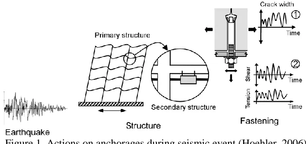
Post-installed mechanical anchors are often required to connect structural or non-structural systems with the reinforced concrete structures in nuclear power plants (NPP). Considering the high safety requirements for nuclear safety related structures, German guideline for anchorages in nuclear power plants (DIBt, 2010) gives recommendations for testing and qualification of anchors to be used in NPP. There is a high probability that the fastener is intercepted by the crack before the earthquake strikes. Consequently, the seismic loading results in cycling of applied load simultaneously with opening and closing of the crack intercepting the anchor. For simplification of the test setup, DIBt (2010) guideline allows the anchors to be tested by separate load and crack cycling tests. The crack cycling tests as per DIBt (2010) guidelines requires the crack to open and close for 10 cycles between the maximum and minimum specified crack widths, while the load on the anchor is kept constant. This assumption of constant load during crack cycling is deemed conservative. In this work, crack cycling tests on undercut anchors qualified for use in NPP are performed with three different tension loading protocols namely, (i) constant load during crack cycling; (ii) load cycling in-phase with crack cycling, and (iii) load cycling out-of-phase with crack cycling. The test results are compared with similar tests on headed studs available in literature. The results indicate that depending on the anchor type, the assumption of constant load during crack cycling may not always be conservative considering the displacement demands on the anchor.
INTRODUCTION
Under seismic actions, the anchors connecting a structural or non-structural component to a parent structure are subjected to cyclic loading. Due to the low tensile strength, concrete members invariably experience cracking, either due to external loading or due to thermal constraints. There is a high probability that fasteners installed in non-cracked concrete will be located in a crack when cracks form (Eligehausen et al., 2006). The anchor load-displacement behaviour is significantly affected by the load acting on the anchor and the crack in which the anchor may be located.
Figure 1. Actions on anchorages during seismic event (Hoehler, 2006)
Mahrenholtz (2013) performed and reported tests on headed studs subjected to simultaneous load- and crack- cycling at a maximum crack width of wmax = 0.5 mm. The crack protocol used for the simultaneous
load and crack cycling tests consisted of applying ten uniform cycles. Different types of loading protocols were used namely: (a) constant load, load and crack cycling at equal frequency with 0° phase difference (in-phase), (b) load and crack cycling at equal frequency with 90° phase difference (out-of-phase), (c) and load and crack cycling at different frequencies. For the tests with an in-phase loading and crack cycling, the displacements after the crack cycling were reduced by about 20% when compared with the corresponding displacements observed in the constant load test. The highest reduction was reported for the out-of-phase load and crack cycling tests where almost 60% reduction in the displacements compared to constant load and crack cycling test was observed. It was concluded, based on these tests, that for a given load level, crack cycling tests are in any case less demanding if the load is simultaneously cycled. However, since the tests were performed on headed studs, these conclusions cannot be generalized, especially for post-installed anchors.
In this work, the simultaneous load- and crack- cycling tests performed on two different types of undercut anchors that are approved for application in German NPP are reported. The tests are evaluated and compared in terms of displacement behavior of anchors and the influence of tension loading protocol during crack cycling tests is clearly brought out. The results of the tests indicate that performing crack cycling tests at constant load may or may not be conservative depending on the type of fastener and maximum crack width.
CRACK CYCLING TESTS FOR ANCHOR QUALIFICATION FOR GERMAN NPP
The German NPP guideline (DIBt, 2010) for anchors required to be qualified for use in nuclear safety related structures recommends a relatively severe crack cycling test. The crack cycling protocol given by this guideline consists only of 10 cycles, that reflect the short duration of the seismic event, but between relatively large crack widths of Δwmax = 1.5mm, and Δwmin = 1.0mm. However, the maximum crack
width for the tests can be reduced if supported with a detailed analysis for the concrete structure in which the anchor is going to be installed. The minimum crack width in such cases is given as Δwmin = Δwmax –
0.5mm for wmax ≥ 1.2mm or 0.0mm for wmax < 1.2 mm, which is achieved by applying a compression
force to the concrete test specimen equal to 15 % of the compressive strength of concrete specimen. A constant tension load given as, Nmax = NRk/γMc is applied on the anchor during the test, where NRk is the
characteristic (5% fractile) load obtained from monotonic reference tests performed at the maximum crack width and γMc is the partial safety factor. Depending on the requirement category and anchor
EXPERIMENTAL WORK
Test Specimen, Setup and Procedure
In order to achieve the required crack width, a special strain split specimen was designed and used to perform the tests. The specimen facilitated in a good control of the crack movement during the crack cycling test. Figure 2 displays schematically, the strain split specimen used for the tests. The specimen used was 320mm deep, 400mm wide and 700mm long. The specimen was provided with four high strength tie rods of 15mm, as longitudinal reinforcement which was bonded to concrete only at the ends and was covered with foamed rubber in the middle 500mm to make it de-bonded. At the mid-section of the specimen, two 2mm thick steel plates were cast (Figure 2a) to act as crack inducer. Two hollow conduits were inserted during casting next to crack inducers and were later pulled out to enable two holes that could be used to generate the crack with split wedges.
a)
b)
Figure 2. a) Test specimen and b) Test setup used for the experimental work
The test setup used for performing the experiments is schematically shown in Figure 2b. The anchor was installed in the pre-generated crack in the specimen as per manufacturer’s guidelines and relevant technical approval. The crack was then opened to the maximum specified crack width value, wmax. The
tension load on the anchor, up to the specified value, was then applied using a servo-hydraulic cylinder placed on the ram and connected to the pull-out fixture assembly (see Figure 2b). After loading the anchor in tension, the crack width was first reduced to its minimum specified value, wmin, and then opened to the
mean crack width value. After this point, ten cycles of crack opening and closing were provided. The load during crack cycling tests was either kept constant or cycled in-phase or cycled out-of-phase with crack cycling, depending on the type of test as discussed in next section. After completion of crack cycling, the
anchor was unloaded, the crack was opened to the maximum specified crack width, wmax and a residual
pull out test is performed on the anchor.
Test Program
Both the anchors had nominal diameter of 12 mm with an effective embedment depth of hef = 125mm
(HDA) and hef = 80mm (FZA).
The test program followed in this work consisted of the following: 1. Monotonic reference tests in non-cracked concrete
2. Monotonic reference tests in cracked concrete with crack width = 1.5mm
3. Crack cycling tests at constant tension load (Constant load test)
4. Crack cycling tests with tension load cycling in-phase with crack (In-phase test)
5. Crack cycling tests with tension load cycling out-of-phase with crack (Out-of-phase test)
For each test series, three tests for each anchor were performed.
TEST RESULTS
Monotonic Tests
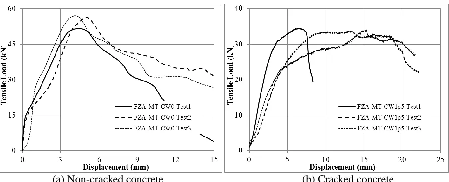
The monotonic reference tests were performed on the anchors in non-cracked and cracked concrete. The test results in the form of applied tension load vs. anchor displacement are plotted in Figure 3a and 3b for tests performed in non-cracked and cracked concrete respectively, on HDA anchors. In case of tests in non-cracked concrete, all the anchors failed by steel rupture and therefore, a very small scatter was observed in the load-displacement curves (Figure 3a). Unlike the tests performed in non-cracked concrete, the tests performed in cracked concrete with a crack width of 1.5mm displayed a high scatter in the displacements undertaken by the anchors (Figure 3b). Due to large crack width, the anchor underwent several small sudden slippages inside the drilled hole, resulting in the several sudden drops in the load-displacement curves. The final failure in test 1 was recorded due to steel failure while for the other two tests it was due to pull out of the anchor. Due to the presence of the crack, the initial stiffness of the anchor was significantly less than that obtained from tests in non-cracked concrete. Even though the failure modes obtained in the tests were different, the scatter in the peak loads was less.
(a) Non-cracked concrete (b) Cracked concrete
Figure 3. Load-displacement curves obtained from monotonic reference tests on HDA® anchor
failure. For the tests performed in cracked concrete, the failure mode for the first test was purely due to concrete breakout. For the other two tests the failure mode was concrete cone breakout influenced by a previous pull out of the anchor. A significant reduction in the peak load due to open crack was observed, which is attributed to the fact that the failure load for concrete breakout is significantly affected by the presence of the crack (Eligehausen et al., 2006; 2013). The influence of the failure modes is also visible in the load-deflection curves where for the tests 2 and 3, significantly larger displacements due to the anchor slippage were observed.
(a) Non-cracked concrete (b) Cracked concrete
Figure 4. Load-displacement curves obtained from monotonic reference tests on FZA® anchor
Crack cycling tests
The crack cycling tests were performed with three different tension load protocols namely: (i) constant tension load (constant load test), (ii) tension load cycling in-phase with crack cycling (in-phase test), and (iii) tension load cycling out-of-phase with crack cycling (out-of-phase test).
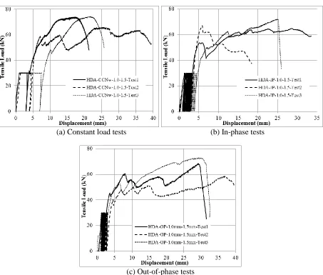
The results of crack cycling tests performed on HDA® anchor are shown in Figure 5 for (a) constant load test, (b) in-phase test, and (c) out-of-phase test. During the crack cycling process, even at constant load, the anchor suffered certain displacements as seen from Figure 5a. The crack cycling was followed by releasing the load on the anchor and then carrying out the residual load test in the open crack.
For constant load tests performed on HDA® anchor, the failure in the first and the third test was due to steel rupture, while for the second test pull out of the anchor was decisive. It can be observed that although the displacement during the residual test clearly depends on the failure mode, the anchor displacement during crack cycling is rather independent of the failure mode. The results also show that the peak failure loads for this anchor are unaffected by crack cycling if the failure mode does not change.
In the in-phase load and crack cycling tests performed on HDA® anchor, the displacement during crack cycling was slightly reduced compared to the displacement observed for the constant load test (Figure 5b). This behavior is in agreement with the findings by Mahrenholtz (2013) for the tests performed on headed stud anchors. For this anchor, the failure load during the residual pull out tests was not affected by the load-cycling protocol during the crack opening and closing. The failure mode in all three cases was a mixed concrete cone and pull out failure of the anchor.
tests and in-phase tests (Figure 5c). This behavior again corresponds to the finding by Mahrenholtz (2013) for the similar tests performed on headed stud anchors. Again, the failure load during the residual pull out tests was not affected by the load-cycling protocol during the crack opening and closing, however the failure loads displayed a larger scatter in this case. The failure in all the three cases was a mixed concrete cone and pull out failure of the anchor.
(a) Constant load tests (b) In-phase tests
(c) Out-of-phase tests
Figure 5. Load-displacement curves obtained from crack cycling tests on HDA® anchor with different tension loading protocols
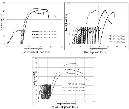
The results of crack cycling tests performed on FZA® anchor are shown in Figure 6 for (a) constant load test, (b) in-phase test, and (c) out-of-phase test. During the crack cycling process, even at constant load, the anchor suffered certain displacements as seen from Figure 6a. The crack cycling was followed by releasing the load on the anchor and then carrying out the residual load test in the open crack.
(a) Constant load tests (b) In-phase tests
0 5 10 15 20 25 30 35 40 45
0 2 4 6 8 10 12
Te
nsil
e
L
oad
(k
N)
Displacement (mm)
FZA-OP-1.0-1.5-Test1
FZA-OP-1.0-1.5-Test2
FZA-OP-1.0-1.5-Test3
(c) Out-of-phase tests
Figure 6. Load-displacement curves obtained from crack cycling tests on FZA® anchor with different tension loading protocols
In the in-phase load and crack cycling tests performed on FZA® anchors these tests, relatively large anchor displacements due to the crack cycling were observed (Figure 6b). For FZA® anchors the results show on average much larger anchor displacements during crack cycling in case of in-phase tests compared to that in case of constant load tests. This is in contrast to the results obtained for HDA® anchors and headed stud anchors reported (Mahrenholtz, 2013). This difference might be attributed to the fact that since the HDA® anchors makes a self-undercut, its general behavior is similar to that of headed studs. On the other hand, in case of FZA® anchor, the undercut is made using a special drill bit prior to the anchor installation and therefore the behavior is in between a headed stud and an expansion anchor. Therefore when the load is applied and released in-phase along with crack opening and closing, further damage is incurred to the concrete against which the anchor bears. Thus with every cycle, the anchor is further pulled out. The failure loads are in the same range as observed in the reference tests for the same crack width. Therefore the results show that the failure loads are not affected by the previous crack cycling. The failure mode in all the tests was concrete cone failure.
gives the lower bound values of the anchor displacements due to crack cycling. However, the failure load at the residual pull out tests was not influenced by the previous out of phase cycling. The failure mode in all the three tests was concrete cone failure.
CONCLUSION
During a seismic event, the load on the anchor cycles simultaneously along with the cycling of the crack. In contrast to that, in laboratory tests, the performance of anchors under seismic events is verified by cycling the cracks and applying a constant load. This assumption of maintaining a constant load during the crack cycling is considered to be conservative.
In this work, the influence of the load cycling protocol on the anchor displacement behavior during crack cycling was investigated experimentally for two different undercut anchors. In general, the guidelines provided by the DIBt (2010) for fastenings in nuclear power plants are followed to obtain the testing parameters (crack width, number of cycles etc.). The crack in which the anchor was installed was cycled between the crack widths of 1.0mm and 1.5mm. Three different loading protocols were used namely, (i) a constant tension load, (ii) a tension load varying cyclically in-phase with crack cycling, and (iii) a tension load varying cyclically out-of-phase with crack cycling.
The results of tests performed on Hilti HDA® anchor results clearly demonstrate that the smallest anchor displacements are observed during out-of-phase crack cycling tests and the largest anchors displacements are observed after the constant load crack cycling tests. These results show a similar influence of tension loading protocol on displacement behavior of HDA® anchors during crack cycling tests as reported by Mahrenholtz (2013) for headed stud anchors.
However, the anchor displacements recorded during the crack cycling tests for fischer FZA® anchor were in contrast with the results observed for HDA® or headed stud anchors (Mahrenholtz, 2013). The tests results clearly demonstrate that, for this anchor, the smallest anchor displacements are observed during out-of-phase crack cycling tests (corresponds to the HDA® and headed stud anchors) but the largest anchors displacements are observed after the in-phase cycling tests.
These test results indicate that the displacement behavior of anchors during crack cycling depends on the type of the anchor as well as on the tension loading protocol. Therefore, the assumption of a constant tension load applied on the anchor during crack cycling tests may or may not be conservative depending on the anchor type, the crack width and/or the embedment depth. Since the seismic event results in simultaneous load and crack cycling, it seems more reasonable to consider cyclic loading and cyclic crack simultaneously, conservatively in-phase. However, for both types of anchors tested in this work, the residual load capacity after the crack cycling with the different tested protocols is not influenced by any load- crack- cycling protocol.
ACKNOWLEDGEMENTS
The presented project was funded by the German Federal Ministry of Economic Affairs and Energy (BMWi, project no. 1501450 and project no. 1501478) on basis of a decision by the German Bundestag.
REFERENCES
DIBt, Deutches Institut für Bautechnik (2010), “Leitfaden für Dübelbefestigungen in Kernkraftwerken und anderen kerntechnischen Anlagen (Guideline for fastenings in nuclear power plants and other nuclear technical facilities)”, Berlin, 23pp (In German).
DIBt: European Organisation for Technical Approvals (2009). “European Technical Approval ETA-98/0004 for fischer-Zykon-Anchor FZA”, DIBt Berlin, 22pp.
Eligehausen, R., Mallée, R. and Silva, J. (2006). Anchorage in Concrete Construction, Wilhelm Ernst & Sohn, Berlin, Germany, 391pp.
Eligehausen, R., Sharma, A. and Hofmann, J. (2013). “On seismic safety issues of post-installed anchors in nuclear power plants” 1st International conference on Technological Innovation in Nuclear Civil Engineering: Construction and Strengthening of Nuclear Buildings (TINCE), Paris, France.
Hoehler, M. S. (2006). “Behavior and Testing of Fastenings to Concrete for use in Seismic Applications” PhD thesis, Institut für Werkstoffe im Bauwesen, University of Stuttgart, Germany, 207 pp.