OBJECT-ORIENTED DEVELOPMENT USING FUSION METHOD SUHAIMI IBRAHIM
Faculty of Computer Science & Information System, UTM, Kuala Lumpur (Former researcher at Aston university, Birmingham)
PAULGOLDER
Department of Computer Science and Applied Mathematics, Aston University, Birmingham, United Kingdom
Abstrak
Kertas kexja ini membincangkan mengenai pembangunan perisian menggunakan suatu metodologi berorientasikan objek yang dinamakan kaedah Fusion. Kaedah ini berasaskan notasi yang lengkap dan tepat dalam keija-keija analisis dan rekabentuk. Fusion boleh digunakan untuk membangunkan sistem berorientasikan objek secara jujukan dan serentak dengan beberapa pertimbangan yang terhad. Kajian kes mengenai perkhidmatan layan diri di stesyen petrol digunakan untuk meninjau sejauh mana kemampuan dan konsistensi pendekatan kaedah ini. C++ digunakan sebagai bahasa perlaksanaan. Skop pembangunan perisian merangkumi analisis, rekabentuk dan perlaksanaan.
Katakunci: Objek, kelas, warisan, atribut, hubungan, agregasi, visibiliti, interaksi Abstract
This paper discusses a software development in the light of object-oriented methodolody, called Fusion method. Fusion is claimed to be based on a concise but comprehensive set of well-defined notations for capturing analysis and design decisions. Fusion can be used to develop sequential object-oriented systems and certain restricted kinds of concurrent systems. A case study on self service petrol pump is used to observe the consistency and completeness of this approach with C++ as an implementation language. The scope of the development covers the analysis, design and implementation.
Keywords : Object, class, inheritance, attribute, relationship, aggregation, visibility, interaction
1.0 CONCEPT OF OBJECT ORIENTATION
Software development is an exciting but messy business. Developers are expected to tackle increasingly complex problems and the enormous flexibility of software means that it can be applied to a widening range of subjects. The abstract nature of most programming allows it to fit almost any domain, but it also deprives as of many intuitions that guide us in our interactions with the physical world.
Object orientation is one approach to programming that attempts to exploit those intuitions. The assence of object-oriented computation, the objects, are likened to objects in the physical world. This produces a programming, model markedly different from the tradition
'functional' view. The object-oriented paradigm as we use it encompasses a few attributes such as
1. Objects have operations that define their behavior and variables that define the state of die object between operation calls.
2. Gasses describe the common behavior of collections of objects.
3. Classes may be specialised by defining a class that adheres to all the behaviors of the original class. Additional behaviors and/or state variables can be defined for the new class. 4. Objects are first-class citizens. They obey the semantics of other types in the language. The third property is often called inheritance. It may be either single or multiple inheritance depending on whether behaviors and/or state variables are obtained from one class or more than one class. It is this property that produces class hierarchies. The original class is called a superclass and the new class is called a subclass. The fourth property is sometimes called aggregation; it allows objects to be composed of other objects [Poo 89]. Smalltalk, C++, objective-C, Eiffel and Flavors are object-oriented languages that support this definition. 2.0 WHAT IS FUSION METHOD ?
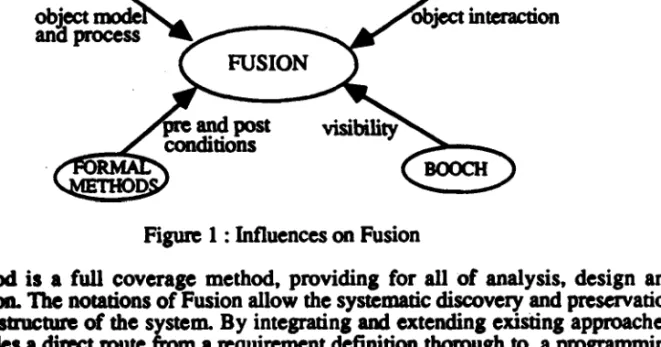
There are now many different development methods specific to object-oriented software. They may loosely be referred to as first generation object-oriented methods, because they arose from applying the notions of object orientation to existing non-object-oriented methods. In this report we present Fusion, a second generation object-oriented software development method. Fusion was developed to provide a systematic approach to object- oriental software development. It integrates and extends the best aspects of several methods. Figure 1 shows the principal influences on Fusion.
Figure 1: Influences on Fusion
Fusion method is a full coverage method, providing for all of analysis, design and implementation. The notations of Fusion allow the systematic discovery and preservation of the object structure of die system. By integrating and extending existing approaches, Fusion provides a direct route from a requirement definition thorough to a programming language implementation.
3.0 BACKGROUND AND REQUIREMENTS
A computer-based system is required to con trol the dispensing of petrol, to handle customer nayment, and to monitor tank levels. Before a customer can use the self-service
pumps, the pump must be enabled by the attendant. When a pump is enabled, the pump motor is started, if it is not already on, with the pump clutch free. When the trigger in the pun is depressed, the clutch is engaged and petrol pumped. When it is released, die clutch is freed.
There is a microswitch on the holster in which the gun is kept that prevents petrol being pumped until the gun is taken out. Once die gun is replaced in the holster, the delivery is deemed to be completed and the pump disabled. Further depressions of the trigger in the gun cannot dispense more petrol. After a short standby period, the pump motor will be turned off unless the pump is reenabled.
A metering device in the petrol line sends a pulse to the system for every 1/100 liter dispensed. Displays on the pump show the amount dispensed and the cost. There are two kinds of pump. The normal kind allows the user to dispense petrol manually. The sophisticated pumps, imported from New Zealand, allow the customer to preset either an amount or a volume of petrol. Petrol will then be pumped up to a maximum of the required quantity.
Transactions are stored until the customer pays. Payment may be either in cash, by credit card, or on account. A customer may request a receipt and will get a token for every RM 10.00 spent. Customers sometimes abscond without paying and the operator must annotate the transaction with any available information (e.g., the vehicle's registration). At the end of the day, transactions are archived and may be used for ad hoc inquiries on sales. At present, two grades of petrol are dispensed from five pumps on the forecourt. Each pump takes its supply from one of two tanks, one tank for each grade. The tank level must not drop below 4% of the tanks capacity. If this happens, the pumps serviced by that tank cannot be enabled to dispense petrol.
4.0 ANALYSIS AND DESIGN
We begin with the analysis phase to build a more precise description than the requirements statement of what the system is supposed to do. We build the object model and use scenarios to help determine the system interface (and hence the system portion of the object model) and construct the life-cycle model. Then the schemata comprising the operation model are developed.
4.1 OBJECT MODEL FOR PROBLEM DOMAIN
A customer uses a pump to deliver petrol and then pays for a delivery (or absconds!). Associated with each customer is the registration number of his or her car. Each pump has a display. A display shows a delivery comprising the cost, volume, and grade of the petrol delivered.
To model the fact that there are five pumps the Pump class has a pump id attribute. The fact that each pump has a display is modeled by an aggregation relationship. The Display class is thus shown nested inside the Pump class. The details of each sale are recorded in a transaction. If the customer absconds the attendant annotates the transaction. The transactions are stored in a daily record, which in turn is stored in the archive for later retrieval.
Each payment can earn tokens. The attendant can also request a receipt for a customer. Finally a pump is supplied by a storage tank. Each storage tank has a capacity, a current level, and an identifying number.
From this part of the requirements we get the following classes and relationships: Classes: These are Transaction, Sale, Attendant,- DailyRecord, Archive,
Token, Receipt, StorageTank.
Relationships: A sale is recorded in a transaction, an-attendant annotates a
transaction, transactions are stored in a daily record, daily records are stored in an archive, each payment earns tokens, an attendant requests a receipt for a payment, a pump is supplied by a storage tank.
This information allows us to draw the fragment of the object model that is centered on the transaction. This is shown in figure 2. We have left the details in the Sale class, because there are some relationships that cross the aggregation boundary.
Storage Tank tank id
Sale
Customer car_reg
Pump pumpjd
I_______ I
Pgfcsra-Yorume lysfon
0..1 payment
payment Archive amount
Figure 2: Object Model for Sale and Transaction
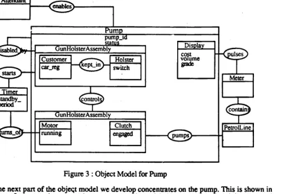
Figure 3 : Object Model for Pump
The next part of the objeqt model we develop concentrates on the pump. This is shown in figure 3. A pump has a complex structure and is modeled by an aggregation; it is composed of a gun, holster, motor, clutch, petrol line, and display. The petrol line contains a meter which sends pulses to the display. A pump may be in one of several states. This is modeled by introducing an attribute, status, which can be either enabled, disabled, or out of service. The attendant can change a pump from being disabled to enabled. A pump is disabled by replacing its gun in its holster.
The requirements state that the pump motor is turned off after a short standby period. To model this we introduce a timer. It starts by replacing the gun in die holster, and turns the motor off after the appropriate standby period. The start relationship is thus a ternary relationship between timer, gun, and holster. This makes the diagram a little difficult to understand, so we have chosen to introduce the GunHolster Assembly aggregation to make the relationship binary.
The clutch and motor are controlled by the GunHolster Assembly, and they pump the petrol down the petrol line. The controls and pumps relationships are thus also ternary, and once again we introduce an aggregate class, ClutchMotorAssembly, to simplify the diagram.
From this part of the requirements we get the following classes and relationships: Classes: Gun, Holster, Motor, Clutch, PetrolLine, Meter, Timer,
G unH olster Assembly, Clutch MotorAssembly.
Relationships: a petrol line contains a meter, a rmeter pulses the display, an attendant enables a pump, a pump is disabled by the gun holster assembly, the gun holster
assembly starts the timer, the time turns off the motor, the gun holster assembly controls the clutch motor assembly, the clutch motor assembly pumps petrol down the petrol line.
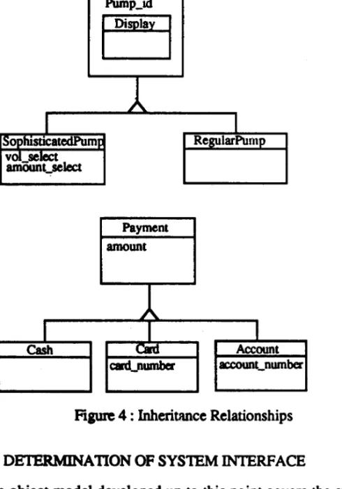
However, the requirements statement contains two examples of generalization. Payments can be made either in cash, by credit card, or on account. These payment methods require different information in each case, and so these are candidates for payment specializations. Also there are two kinds of pump: the simple one that we have already described in our models, and the sophisticated version from New Zealand, which allows the customer to preset the volume or amount. This can also be modeled by an inheritance relationship. We will make no decision about whether the subclasses are a disjoint union or not, so we leave the triangles empty. These inheritance relationships are shown in figure 4.
Figure 4 : Inheritance Relationships 4.2 DETERMINATION OF SYSTEM INTERFACE
The object model developed up to this point covers the system and its environment. The next step in Fusion involves determining the boundary between the system and its environment Once we have done this we can identify those classes and relationship that form part of the system and die information that the system should record.
In this phase of the analysis we use scenarios to help identify the system boundary. These allow us to trace through the likely use of the system in terms of its Interactions with the external environment We can develop scenarios for the following three uses of the system: • Delivery of petrol
• Payment for delivery • Display of delivery
Figure 5 shows the scenario of the delivery of petrol. This scenario clearly reveals that customer and attendant are active agents that lie outside the system. They interact with the system to achieve the delivery. The scenario also identifies a number of system operations: e n a b l e _ p u m p , r e m o v e g u n , d e p r e s s t r i g g e r , r e l e a s e _ t r i g g e r , and replace_gun. The same principles of scenario also apply to die payment^for delivery and display of delivery.
| Timer | Customer | 1 System |
Time
Attendant remove_gun ^ ^enable_pump depress_triggei^
w
release_trigger ^ replace_gun ^ ^ start timer
w
Figure 5 : Scenario for Delivery of Petrol 4.3 LIFE CYCLE MODEL
At this point in the development we can do either of two things. We can use the scenarios to develop the life-cycle model, or we can use the output of the scenarios to build the system object model and the operation model. We have chosen to develop die life cycle. The life cycle of the system is essentially a sequence of delivery followed by payment It is also possible that the pumps are taken out of service if die tank levels fall too low. At the end of the day the transactions are archived. This is captured by the following regular expression:
lifecycle FetiolStation: ((Delivery. Payment)411 PumpsOutOfService)* . archive
D elivery, P ay m en t and P um psO utO fS ervice expand to regular expressions describing the sequence of system operations and events that achieve them. The regular expression also includes some extra interactions generated by the sophisticated pumps. Thus the line labeled (a) permits an optional preset of amount or volume, and die line labeled (b) allows the delivery to be terminated not only by a release_trigger event but also by a cut_off_supply generated when the required amount or- volume has been delivered. ~
Delivery = enable pump. [start pump motor].
[(preset volume I preset amount)]. // (a) remove gun from holster,
depress trigger.
(pulse. #display amount )* .
(release trigger I cut off supply). // (b) replace gun.
#start timer. [turn off motor]
Payment = NormalPayment I CustomerAbsconds NormalPayment = enter_payment_details. #dispense_tokens.
[request_receipt. #dispense_receipt] CustomerAbsconds = enter_annotation
PumpsOutOfService = tapk_level_low.
#take_pumps_out_of_service 4.4 OBJECT INTERACTION GRAPHS
An object interaction graph is produced for each system operation. It shows what objects are involved in the computation and defines how they collaborate. We will develop an object interaction graph for each of the operations for which we built schemata.
(1) enable
enable_pum]lg) Terminal Pumps: Pump
(1.1)
reset. Display
(1.3) start T
Motor l
(1.2)
finee Clutch
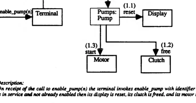
Description.:
On receipt o f the call to enable_pump(n) the terminal invokes enable jnim p with identifier n. If the pump is in service and not already enabled then its display is reset, its clutch is freed, and its motor is started.
Figure 6 : Object Interaction Graph for enable_pump
The first step is to identify the objects (and possibly agents) that are involved in the realization of a system operation. For enable_pump the objects involved are a Pump, Display, Motor, and Clutch. Because the attendant invokes this operation, a Terminal must also be involved, because this is how the attendant interacts with the system. In the second step the role of each object in implementing the operation is decided. One distinguished role is that of the controller. The controller receives the system operation
message. In this example we will take the terminal as the controller because it is the part of die system with which the invoking agent (the attendant) interacts. This means that the other objects axe the collaborators.
The third step is to decide how the functionality of the operation is distributed among the various objects involved. It would seem appropriate for the Pump to be responsible for starting the Motor, resetting the Display, and freeing the Clutch, because they are all components of the Pump. The Terminal then only needs to invoke enable_pump with the appropriate pump number. In the final step, the distribution of functionality of the system operation is recorded in an object interaction graph. The object interaction graph for enable_pump is shown in figure 6. We can also construct the object interaction graphs for the other operations such as remove_gun, replace_gun, depress_trigger arid release_trigger.
5.0 IMPLEMENTATION
In this section we look at implementing the class descriptions for Pump and Gun. The information we need for this task has already been collected up into the class descriptions so this task is essentially one of translating them into the implementation language.
First consider Pump. The first step is to translate the attributes from the class description into C++ declarations. Pump has two value attributes, pump_id and status, and four object-valued attributes, term inal, motor, display, and timer. We will define the p u m p jd to be a C++ int, with a comment that it should be in the range 0 to 4. The status will be defined as a C++ enumeration type.
We make all attributes protected rather than private, because we know that there is a derivation of pump, namely, sophisticatedPump. The reference members must be initialized when a Pump is created. We do this by declaring a constructor for Pump, which takes references to the appropriate objects as parameters.
class Pump { protected:
int pump id; //Value between 0 and 4 PumpStatus status;
Terminal &terminal; Clutch clutch; Motor motor; Display display; Timer &timer, public:
Pump( Tenmnal &term, Timer &tim ) //Constructor : tenmnal(term), timer(tim) {} // initializes references virtual void enabhK );
virtual void disable( ); virtual int is_enabled( );
virtual void delivery_complete( ); };
Figure 7 : C++ Class Definition for Pump
There are four operations: enable, disable, is enabled, and delivery_complete. Because we know that Pump is a superclass we will make all the methods virtual, that is, redefinable. The methods have no parameters, and only is.enabled has a return value (of type Boolean). The usual representation of Boolean values in C++ is int. Figure 7 shows the resulting C++ class definition.
The next step is to develop the declaration for the methods of Pump, for example the operation enable. The object interaction graph for this operation was shown in figure 6. TTie Display, Clutch and Motor are all attributes of the Pump, so there are no parameters and no local variables. The code for enable is shown in figure 8.
void Pump :: enable() {
display .reset(); clutch.free(); motor. start(); }
Figure 8 : C++ for enable on Pump
Gun is another class description. The full class definition for the Gun is shown in figure 9. The detail implementations of Gun operations can be further derived, as we did for the Pump.
class Gun { private:
int trigger, // 0 = released, 1 = depressed int status; // 0 = disabled, 1 = enabled Clutch clutch;
const Pump &pump; public:
Gun( Pump & p): pump(p) {} void depress_trigger(); void release_trigger(); void gun_enable(); void gun_disable(); int gun_is_enabled();
Figure 9 : C++ Class Definition for Gun 6.0 CONCLUSION
The project of implementing automated petrol pump was carried out using the technique of object-oriented methodology, called Fusion method. This method was principally based on several other methods and proved successful in the requirements analysis, design and implementation. The functional requirements have been well refined in terms of classes, relationships and its interfaces. The solution coverage is more comprehensive and complete, however it requires detailed study and understanding of several methods in analysis and design. The emergence of Fusion method in the object-oriented methodology has considerably reduced the software crisis in the area of software development and maintenance.
REFERENCES
1) Booch, G. (1991), Object-oriented Analysis and Design, second edition, The Benjamin/Cummings Publishing Co.
2) Scharenberg, M.E. & Dunsmore, H.E. (1991), "Evolution of classes and objects during object-oriented design and programming", JOOP, January, pp 30 - 34.
3) Winbland, A.L. (1990), Object-Oriented Software, Addision Wesley.
4) Coleman, D. (1994), Object-oriented Development The Fusion Method, Prentice Hall. 5) Pinson, L.J. & Wiener, R.S. (1988), An Introduction to Object-oriented Programming and Smalltalk, Addison Wesley.
6) Capretz, L.F. & Lee, P.A. (1993), "Object-oriented design: guidelines and techniques",
Information and Software Technology, vol 35(4), pp 195 - 206.
7) Eckert, G. & Golder, P. (1994), "Improving object-oriented analysis", Information and Software Technology , vol 36(2) pp 67 - 86.
8) Gilliam, C. (1994), "An approach for using OMT in the development of large system",
JOOP, February, pp 56 - 59.
9) Poo, Loh & Kazmi (1989), "An approach to object-oriented system specification based on the Jackson System Development Method", Technical Report 11/89, National University of Singapore.