User Interface Guide (UIG)
Trademarks
Any brand names and product names included in this manual are trademarks, registered trademarks, or trade names of their respective holders.
To the Holder of the Manual
The contents of this manual are current as of the date of publication. ADTRAN reserves the right to change the contents without prior notice.
In no event will ADTRAN be liable for any special, incidental, or consequential damages or for commercial losses even if ADTRAN has been advised thereof as a result of issue of this publication.
901 Explorer Boulevard
P.O. Box 140000
Huntsville, AL 35814-4000
Safety Instructions
When using your telephone equipment, please follow these basic safety precautions to reduce the risk of fire, electrical shock, or personal injury:
1. Do not use this product near water, such as a bathtub, wash bowl, kitchen sink,
laundry tub, in a wet basement, or near a swimming pool.
2. Avoid using a telephone (other than a cordless-type) during an electrical storm.
There is a remote risk of shock from lightning.
3. Do not use the telephone to report a gas leak in the vicinity of the leak.
4. Use only the power cord, power supply, and/or batteries indicated in the
man-ual. Do not dispose of batteries in a fire. They may explode. Check with local
codes for special disposal instructions.
Save These Important Safety Instructions
Notes provide additional useful information.
Caution signify information that could prevent service interruption.
FCC regulations require that the following information be provided in this manual
to the customer:
1. This equipment complies with Part 68 of the FCC rules. On the side of the
bot-tom of this equipment is a label that contains, among other information, the
FCC Registration Number and Ringer Equivalence Number (REN), if
applica-ble, for this equipment. If required, this information must be given to the
tele-phone company.
2. An FCC-compliant telephone cord and modular plug is provided with this
equipment. This equipment is designed to be connected to the telephone
net-work or premises wiring using a compatible modular jack which is Part
68-compliant. See installation instructions for details.
3. If your telephone equipment (Total Access 600R) causes harm to the telephone
network, the telephone company may discontinue your service temporarily. If
possible, they will notify you in advance. But if advance notice isn’t practical,
you will be notified as soon as possible. You will be advised of your right to
file a complaint with the FCC.
4. Your telephone company may make changes in its facilities, equipment,
opera-tions, or procedures that could affect the proper operation of your equipment. If
they do, you will be given advance notice to give you an opportunity to
main-tain uninterrupted service.
5. If you experience trouble with this equipment (Total Access 600R), please
con-tact ADTRAN for repair/warranty information. The telephone company may
ask you to disconnect this equipment from the network until the problem has
been corrected or until you are sure the equipment is not malfunctioning.
6. This unit contains no user-serviceable parts.
7. The FCC recommends that the AC outlet to which equipment requiring AC
power is to be installed is provided with an AC surge arrester.
8. The REN is used to determine the quantity of devices which may be connected
to the telephone line. Excessive RENs on the telephone line may result in the
devices not ringing in response to an incoming call. In most, but not all areas,
the sum of RENs should not exceed five (5.0). To be certain of the number of
devices that may be connected to a line, as determined by the total RENs,
con-tact the local telephone company.
tele-Federal Communications Commission (FCC) Statement
This equipment has been tested and found to comply with the limits for a Class A digital device,
pursuant to Part 15 of the FCC Rules. These limits are designed to provide reasonable protection
against harmful interference when the equipment is operated in a commercial environment. This
equipment generates, uses, and can radiate radio frequency energy and, if not installed and used in
accordance with the instruction manual, may cause harmful interference to radio frequencies.
Operation of this equipment in a residential area is likely to cause harmful interference in which
case the user will be required to correct the interference at his own expense.
Industry Canada Compliance Information
Notice: The Industry Canada label applied to the product (identified by the Industry Canada logo or the
“IC:” in front of the certification/registration number) signifies that the Industry Canada technical
specifications were met.
Notice: The Ringer Equivalence Number (REN) for this terminal equipment is supplied in the
documentation or on the product labeling/markings. The REN assigned to each terminal device indicates
the maximum number of terminals that can be connected to a telephone interface. The termination on an
interface may consist of any combination of devices subject only to the requirement that the sum of the
RENs of all the devices should not exceed five (5).
Canadian Emissions Requirements
This digital apparatus does not exceed the Class A limits for radio noise emissions from digital apparatus
as set out in the interference-causing equipment standard entitled “Digital Apparatus,” ICES-003 of the
Department of Communications.
Affidavit Requirements for Connection to Digital Services
•
An affidavit is required to be given to the telephone company whenever digital terminal
equipment without encoded analog content and billing protection is used to transmit digital
signals containing encoded analog content which are intended for eventual conversion into
voiceband analog signals and transmitted on the network.
•
The affidavit shall affirm that either no encoded analog content or billing information is being
transmitted or that the output of the device meets Part 68 encoded analog content or billing
protection specifications.
•
End user/customer will be responsible for filing an affidavit with the local exchange carrier
when connecting unprotected customer premise equipment (CPE) to 1.544 Mbps or subrate
digital services.
Affidavit for Connection of Customer Premises Equipment
to 1.544 Mbps and/or Subrate Digital Services
For the work to be performed in the certified territory of ___________________(telco name)
State of ________________
County of ________________
I, _______________________ (name), _____________________________(business address),
____________________ (telephone number) being duly sworn, state:
I have responsibility for the operation and maintenance of the terminal equipment to be
connected to 1.544 Mbps and/or ________ subrate digital services. The terminal equipment
to be connected complies with Part 68 of the FCC rules except for the encoded analog
content and billing protection specifications. With respect to encoded analog content and
billing protection:
( ) I attest that all operations associated with the establishment, maintenance, and adjustment of
the digital CPE with respect to analog content and encoded billing protection information
con-tinuously complies with Part 68 of the FCC Rules and Regulations.
( ) The digital CPE does not transmit digital signals containing encoded analog content or billing
information which is intended to be decoded within the telecommunications network.
( ) The encoded analog content and billing protection is factory set and is not under the control of
the customer.
I attest that the operator(s)/maintainer(s) of the digital CPE responsible for the
establish-ment, maintenance, and adjustment of the encoded analog content and billing information
has (have) been trained to perform these functions by successfully having completed one of
the following (check appropriate blocks):
( ) A. A training course provided by the manufacturer/grantee of the equipment used to encode
analog signals; or
I agree to provide ______________________ (telco’s name) with proper documentation to
demonstrate compliance with the information as provided in the preceding paragraph, if so
requested.
_________________________________Signature
_________________________________Title
_________________________________ Date
Transcribed and sworn to before me
This ________ day of _______________, 20____
_________________________________
Notary Public
My commission expires:
Warranty and Customer Service
ADTRAN will repair and return this product within ten years from the date of shipment if it does not meet
its published specifications or fails while in service. For detailed warranty, repair, and return information
refer to the ADTRAN Equipment Warranty and Repair and Return Policy Procedure.
Return Material Authorization (RMA) is required prior to returning equipment to ADTRAN.
For service, RMA requests, or further information, contact one of the numbers listed at the end of this
section.
LIMITED PRODUCT WARRANTY
ADTRAN warrants that for ten years from the date of shipment to Customer, all products manufactured by
ADTRAN will be free from defects in materials and workmanship. ADTRAN also warrants that products
will conform to the applicable specifications and drawings for such products, as contained in the Product
Manual or in ADTRAN's internal specifications and drawings for such products (which may or may not be
reflected in the Product Manual). This warranty only applies if Customer gives ADTRAN written notice of
defects during the warranty period. Upon such notice, ADTRAN will, at its option, either repair or replace
the defective item. If ADTRAN is unable, in a reasonable time, to repair or replace any equipment to a
condition as warranted, Customer is entitled to a full refund of the purchase price upon return of the
equipment to ADTRAN. This warranty applies only to the original purchaser and is not transferable
without ADTRAN's express written permission. This warranty becomes null and void if Customer
modifies or alters the equipment in any way, other than as specifically authorized by ADTRAN.
EXCEPT FOR THE LIMITED WARRANTY DESCRIBED ABOVE, THE FOREGOING
CONSTITUTES THE SOLE AND EXCLUSIVE REMEDY OF THE CUSTOMER AND THE
EXCLUSIVE LIABILITY OF ADTRAN AND IS IN LIEU OF ANY AND ALL OTHER WARRANTIES
(EXPRESSED OR IMPLIED). ADTRAN SPECIFICALLY DISCLAIMS ALL OTHER WARRANTIES,
INCLUDING (WITHOUT LIMITATION), ALL WARRANTIES OF MERCHANTABILITY AND
FITNESS FOR A PARTICULAR PURPOSE. SOME STATES DO NOT ALLOW THE EXCLUSION
OF IMPLIED WARRANTIES, SO THIS EXCLUSION MAY NOT APPLY TO CUSTOMER.
Customer Service, Product Support Information, and Training
ADTRAN will repair and return this product if within ten years from the date of shipment the product does
not meet its published specification or the product fails while in service.
A return material authorization (RMA) is required prior to returning equipment to ADTRAN. For service,
RMA requests, training, or more information, use the contact information given below.
Repair and Return
If you determine that a repair is needed, please contact our Customer and Product Service (CAPS)
department to have an RMA number issued. CAPS should also be contacted to obtain information
regarding equipment currently in house or possible fees associated with repair.
Identify the RMA number clearly on the package (below address), and return to the following address:
ADTRAN Customer and Product Service 901 Explorer Blvd. (East Tower)
Huntsville, Alabama 35806
RMA # _____________
Pre-Sales Inquiries and Applications Support
Your reseller should serve as the first point of contact for support. If additional pre-sales support is needed,
the ADTRAN Support web site provides a variety of support services such as a searchable knowledge
base, latest product documentation, application briefs, case studies, and a link to submit a question to an
Applications Engineer. All of this, and more, is available at:
http://support.adtran.com
When needed, further pre-sales assistance is available by calling our Applications Engineering
Department.
CAPS Department (256) 963-8722
Post-Sale Support
Your reseller should serve as the first point of contact for support. If additional support is needed, the
ADTRAN Support web site provides a variety of support services such as a searchable knowledge base,
updated firmware releases, latest product documentation, service request ticket generation and
trouble-shooting tools. All of this, and more, is available at:
http://support.adtran.com
When needed, further post-sales assistance is available by calling our Technical Support Center. Please
have your unit serial number available when you call.
Installation and Maintenance Support
The ADTRAN Custom Extended Services (ACES) program offers multiple types and levels of installation
and maintenance services which allow you to choose the kind of assistance you need. This support is
available at:
http://www.adtran.com/aces
For questions, call the ACES Help Desk.
Training
The Enterprise Network (EN) Technical Training Department offers training on our most popular products.
These courses include overviews on product features and functions while covering applications of
ADTRAN's product lines. ADTRAN provides a variety of training options, including customized training
and courses taught at our facilities or at your site. For more information about training, please contact your
Territory Manager or the Enterprise Training Coordinator.
Technical Support (888) 4ADTRAN
ACES Help Desk (888) 874-ACES (2237)
Training Phone (800) 615-1176, ext. 7500
Training Fax (256) 963-6700
TOTAL ACCESS 600R USER INTERFACE GUIDE
This User Interface Guide is designed for use by network administrators and others who will configure and provision the system. It contains information about navigating the VT 100 user interface, configuration information, and menu descriptions.
T
ABLEOFC
ONTENTSNavigating the Terminal Menu . . . 15
Terminal Menu Window . . . 15
Navigating using the Keyboard Keys . . . 17
Terminal Menu and System Control . . . 20
Selecting the Appropriate Menu . . . 20
Security Levels . . . 20
Configuring the Total Access 600R . . . 21
System Info . . . 21
System Info>System Name . . . . 21
System Info>System Location . . . . 21
System Info>System Contact . . . 21
System Info>Unit Name . . . 21
System Info>Part Number. . . 22
System Info>Serial Number . . . 22
System Info>Firmware Revision . . . 22
System Info>Bootcode Revision . . . 22
System Info>System Uptime. . . 22
System Info>Date/Time . . . 22
System Config. . . 23
System Config>Operating Mode. . . 23
System Config>T1 Timing Mode. . . 23
System Config>Telnet Access . . . . 23
System Config>Telnet User List . . . . 23
System Config>Telnet IP Access List . . . 24
System Config>SNMP Menu . . . 25
System Config>Maint Port Menu . . . 26
System Config>Network Time . . . 27
System Utility . . . 28
System Utility>Upgrade Firmware . . . 29
System Utility>Config Transfer . . . 29
System Utility>Ping . . . 31
System Utility>Terminal Mode . . . 31
Router Menus . . . 32
Router>Config. . . 32
Router>Status . . . 54
Router>Logs . . . 59
Modules Menus. . . 61
Modules>Modules. . . 61
Modules>DS0 Maps . . . 64
Initial Setup . . . 66
Initial Setup . . . 72
Setting up Bridging Options . . . 72
F
IGURES Figure 1. Top-Level Terminal Menu Window . . . 15Figure 2. Alternate Menu View . . . 16
Figure 3. System Information Menu . . . 21
Figure 4. System Config Menu . . . 23
Figure 5. System Utility Menu . . . 28
Figure 6. Router/Configuration Menu . . . 32
Figure 7. Global Menu. . . 32
Figure 8. Ethernet Menu . . . 38
Figure 9. WAN Menu. . . 40
Figure 10. Router/Status Menu . . . 54
Figure 11. Router/Logs Menu . . . 60
1.
NAVIGATING THE TERMINAL MENU
Terminal Menu Window
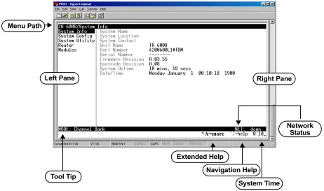
The Total Access 600R uses a multi-level menu structure that contains both menu items and data fields. All menu items and data fields display in the terminal menu window (see Figure 1), through which you have complete control of the Total Access 600R.
Figure 1. Top-Level Terminal Menu Window
Menu Path
The first line of the terminal menu window (the menu path) shows the session’s current position (path) in the menu structure. For example, Figure 1 shows the top-level menu with the cursor on the SYSTEM INFOsubmenu; therefore, the menu path reads TA 600R/SYSTEM INFO.
Left Pane Menu Path
Right Pane
Tool Tip
System Time Navigation Help Extended Help
^A=more
Window Panes
When you first start a terminal menu session, the terminal menu window is divided into left and right panes. The left pane shows the list of available submenus, while the right pane shows the contents of the currently selected submenu. You can view the terminal windows in two ways: with fields and submenus displaying horizontally across the right pane, or with fields and submenus displaying vertically down the right pane. Viewing submenus vertically rather than horizontally allows you to see information at a glance rather than scrolling horizontally across the window. To change the view, move your cursor to an index number and press <Enter>. Figure 2 shows this alternate view. Fields and sub-menu names may vary slightly in this view.
Window Pane Navigation
Use the following chart to assist you in moving between and within the two window panes.
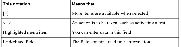
Right Window Pane Notation
The right window pane shows the contents of the currently selected menu. These contents can include both submenu items and data fields. Some submenus contain additional submenus and some data fields contain additional data fields. The following chart explains the notation used to identify these additional items.
Additional Terminal Menu Window Features
• Tool Tip - provides a brief description of the currently selected mode • Network Status - displays network status information, Up or Down
• Extended Help - displays information about selected commands (CTRL+A)
• Navigation Help - lists characters used for navigating the terminal menu and session management (CTRL+Z) • System Time - displays current time
Navigating using the Keyboard Keys
You can use various keystrokes to move through the terminal menu, to manage a terminal menu session, and to con-figure the system. Press <CTRL+Z> to activate a pop-up screen listing the navigation keystrokes.
To do this... Press this key...
Move from left pane to right pane Tab Enter Right arrow Move from right pane to left pane Tab
Escape Left arrow Backspace Move within each pane Up arrow
Down arrow Left arrow Right arrow
This notation... Means that...
[+] More items are available when selected
<+> An action is to be taken, such as activating a test Highlighted menu item You can enter data in this field
Moving through the Menus
Session Management Keystrokes
To do this... Press this key...
Return to the home screen H
Jump between two menu items
Press <J> while the cursor is located on a menu item, and you jump back to the main screen. Go to another menu item, press <J>, and you jump back to the screen that was displayed the first time you pressed <J>.
Press <J> anytime you want to jump between these items.
J
Select items Arrows
Edit a selected menu item Enter
Cancel an edit Escape
Close pop-up help screen Escape
Move between the left and right panes Tab
Arrows
Move to the top of a screen A
Move to the bottom of a screen Z
Ascend one menu level Backspace
To do this... Press this key...
Log out of a session CTRL+L
Refresh the screen
To save time, only the portion of the screen that has changed is refreshed. This option should only be necessary if the display picks up incorrect characters.
Configuration Keystrokes
Getting Help
The bottom line of the terminal menu window contains context-sensitive help information. When the cursor is posi-tioned over a set of configuration items, a help message displays (when available) providing a description of the item. When more detailed help is available for a particular item, ^A displays at the bottom of the window. At this point, if you press <CTRL+A>, a pop-up help screen displays with information about the item.
Press <CTRL+Z> to activate a help screen that displays the available keystrokes you can use to navigate the terminal menu.
Press <ESC> to cancel these pop up windows.
To do this... Press this key...
Restore factory default settings.
This setting restores the factory defaults based on the location of the cursor. If the cursor is on a module line (in the MODULES menu), then only the selected module is updated to fac-tory defaults.
F
Copy selected items to the clipboard.
The amount of information you can copy depends on the cursor location when you press <C>:
If the cursor is over an editable field, only that item is copied.
If the cursor is over the index number of a list, then all of the items in the row of the list are copied. For example, if the cursor is over the DS0 field in the MAP 1 screen, all of the in-formation associated with the DS0 is copied.
C
Paste the item stored in the clipboard, if the information is compatible. You must confirm all pastes - except those to a single editable field.
P
Increment the value of certain types of fields by one when you paste information into those fields.
>
Decrement the value of certain types of fields by one when you paste information into those fields.
<
Insert a new list item.
For example, add a new item to the TELNET USER LIST connection list by pressing <I> while the cursor is over the index number.
I
Delete a list item.
For example, delete an item from the TELNET USER LISTconnection list by pressing <D>
while the index number is active.
2.
TERMINAL MENU AND SYSTEM CONTROL
Selecting the Appropriate Menu
The terminal menu is the access point to all other operations. Each terminal menu item has several functions and sub-menus that identify and provide access to specific operations and parameters. Use the chart below to help select the appropriate terminal menu.
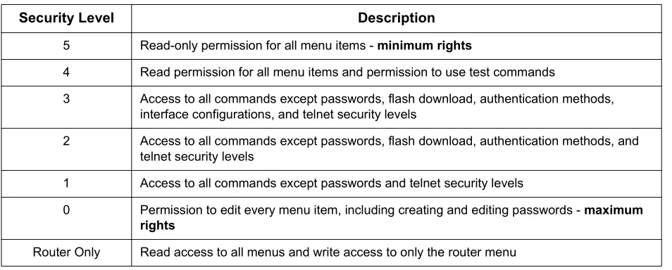
Security Levels
To edit terminal menu items, you must have a password and the appropriate security level. Table 1 describes the secu-rity levels.
To do this... Go to this menu...
Review and monitor general system information for the Total Access 600R SYSTEM INFO
Set up the operational configuration for the Total Access 600R SYSTEM CONFIG
Upgrade firmware, do config transfers, ping, and access terminal mode SYSTEM UTILITY
Define, configure, and monitor all Total Access 600R Router functions ROUTER
Review and configure settings for the network interface and configure the DS0
maps M
ODULES
Table 1. Password Security Level
Security Level Description
5 Read-only permission for all menu items - minimum rights
4 Read permission for all menu items and permission to use test commands
3 Access to all commands except passwords, flash download, authentication methods, interface configurations, and telnet security levels
2 Access to all commands except passwords, flash download, authentication methods, and telnet security levels
1 Access to all commands except passwords and telnet security levels
0 Permission to edit every menu item, including creating and editing passwords - maximum rights
3.
CONFIGURING THE TOTAL ACCESS 600R
S
YSTEMI
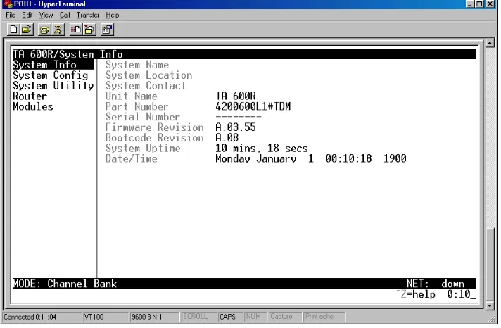
NFOThe SYSTEM INFO menu provides basic information about the unit as well as data fields for editing information. Figure
3 displays the submenus that are available when you select this menu item.
Figure 3. System Information Menu
S
YSTEMI
NFO>S
YSTEMN
AMEProvides a user-configurable text string for the name of the Total Access 600R. This name can help you distinguish between different installations. You can enter up to 31 alpha-numeric characters in this field, including spaces and spe-cial characters (such as an underscore). This name will appear on the top line of all screens. The factory default is to have no entry in the system name field.
S
YSTEMI
NFO>S
YSTEML
OCATIONProvides a user-configurable text string for the location of the Total Access 600R. This field is to help you keep track of the actual physical location of the unit. You can enter up to 31 alphanumeric characters in this field, including spaces and special characters (such as an underscore). The factory default is to have no entry in the system location field.
S
YSTEMI
NFO>S
YSTEMC
ONTACTProvides a user-configurable text string for a contact name. You can use this field to enter the name, phone number, or email address of a person responsible for the Total Access 600R system. You can enter up to 31 alpha-numeric char-acters in this field, including spaces and special charchar-acters (such as an underscore). The factory default is to have no entry in the system contact field.
S
YSTEMI
NFO>P
ARTN
UMBERADTRAN part number for the Total Access 600R.
S
YSTEMI
NFO>S
ERIALN
UMBER Serial number of the Total Access 600R.S
YSTEMI
NFO>F
IRMWARER
EVISIONDisplays the current firmware revision level of the Total Access 600R.
S
YSTEMI
NFO>B
OOTCODER
EVISION Displays the bootcode revision.S
YSTEMI
NFO>S
YSTEMU
PTIMEDisplays the length of time since the last Total Access 600R system reboot.
S
YSTEMI
NFO>D
ATE/T
IMEDisplays the current date and time, including seconds. This field can be edited. Enter the time in 24-hour format (such as 23:00:00 for 11:00 pm). Enter the date in mm-dd-yyyy format (for example, 10-30-1998).
S
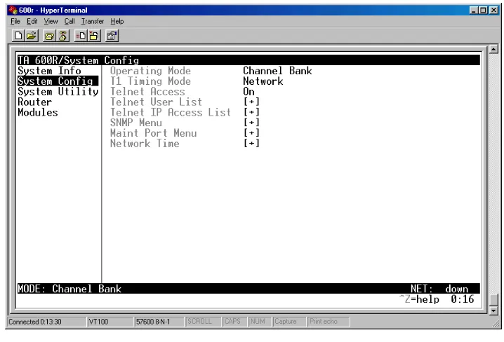
YSTEMC
ONFIGSet up the Total Access 600R operational configuration from the SYSTEM CONFIG menu. Figure 4 shows the items
included in this menu.
Figure 4. System Config Menu
S
YSTEMC
ONFIG>O
PERATINGM
ODEFor the T1 TDM application, the mode will be displayed as Channel Bank.
S
YSTEMC
ONFIG>T1 T
IMINGM
ODEThe T1 TIMING MODE choices are NETWORKand INTERNAL. SelectNETWORKif the TELCO is providing clocking on the T1 line. SelectINTERNALif there is no timing on the T1 circuit and the 600R will have to provide the clock. Default is
NETWORK.
S
YSTEMC
ONFIG>T
ELNETA
CCESSSets Telnet access to ON or OFF. The factory default value for this parameter is ON.
S
YSTEMC
ONFIG>T
ELNETU
SERL
ISTS
YSTEMC
ONFIG>T
ELNETU
SERL
IST>N
AMES
YSTEMC
ONFIG>T
ELNETU
SERL
IST>A
UTHENM
ETHOD The user can be authenticated by selecting:The factory default is password.
S
YSTEMC
ONFIG>T
ELNETU
SERL
IST>P
ASSWORDWhen the authenticating method is password, this text string is used for the password. You can enter up to 15 characters in this field. The factory default is no entry in this field.
S
YSTEMC
ONFIG>T
ELNETU
SERL
IST>I
DLET
IME(
MINS)
This sets the amount of time in minutes you can be idle before you are automatically logged off. The factory default is 10 MINUTES. The range is 1-255 MINUTES.
S
YSTEMC
ONFIG>T
ELNETU
SERL
IST>L
EVELThis is the security level granted to the user. The table below gives a brief description of each level. The factory default is 0.
S
YSTEMC
ONFIG>T
ELNETIP A
CCESSL
ISTS
YSTEMC
ONFIG>T
ELNETIP A
CCESSL
IST>N
ETWORKA
DDRESSANDM
ASK PASSWORD The Password field is used to authenticate the user.RADIUS The Radius client is used for authenticating the user.
Select level... If you want the user to....
5 Have read-only permission for all menu items - minimum rights
4 Have read permission for all menu items and permission to use test commands
3 Have access to all commands except passwords, flash download, authentication methods, interface configurations, and telnet security levels.
2 Have access to all commands except passwords, flash download, authentication methods, and telnet security levels.
1 Have access to all commands except passwords and telnet security levels.
0 Have permission to edit every menu item, including creating and editing passwords -- maximum rights
S
YSTEMC
ONFIG>SNMP M
ENUS
YSTEMC
ONFIG>SNMP M
ENU>A
CCESSThe Total Access 600R is an SNMP agent. The SNMP Menu parameters set up the manager, communities, and levels. When set to OFF, SNMP access is denied. When set to ON, the 600R will respond to SNMP managers based on the configuration. The factory default is ON.
S
YSTEMC
ONFIG>SNMP M
ENU>C
OMMUNITIESS
YSTEMC
ONFIG>SNMP M
ENU>C
OMMUNITIES>N
AMEThis list is used to set up to 60 SNMP communities names that the 600R will allow. This is a text string for the community name. You can enter up to 31 characters in this field. The factory default is no entry in the name parameter.
S
YSTEMC
ONFIG>SNMP M
ENU>C
OMMUNITIES>P
RIVILEGEThe access for this manager can be assigned three levels. The factory default is NONE.
S
YSTEMC
ONFIG>SNMP M
ENU>C
OMMUNITIES>M
ANAGERIP
This is the IP address of the SNMP manager. If set to 0.0.0.0, any SNMP manager can access the Total Access 600R for this community. The factory default is 0.0.0.0.
S
YSTEMC
ONFIG>SNMP M
ENU>T
RAPSS
YSTEMC
ONFIG>SNMP M
ENU>T
RAPS>M
ANAGERN
AMEThe 600R can generate SNMP traps. This list allows up to four managers to be listed to receive traps.
MANAGER NAME is the text string describing the name of the entry. It is intended for easy reference and has no bearing on the SNMP trap function. You can enter up to 31 characters in this field. The factory default is no entry in the manager name field.
S
YSTEMC
ONFIG>SNMP M
ENU>T
RAPS>M
ANAGERIP
This is the IP address of the manager that is to receive the traps. The factory default is 0.0.0.0.
S
YSTEMC
ONFIG>SNMP M
ENU>FDL
S
YSTEMC
ONFIG>SNMP M
ENU>FDL>M
ODEThis enables the FDL (only in ESF mode) to be used for management. Learning mode can also be enabled so the Total Access 600R can “learn” its IP configuration to be used for its FDL management. Once it learns this information from, for example a Total Access 4303, the configuration items populate. The factory default is ON.
S
YSTEMC
ONFIG>SNMP M
ENU>FDL>L
INKIP A
DDRESSThis is the local IP address used for the FDL management. The FDL uses a separate IP network for communication, distinct from the customer data configured under the ROUTER menus. The factory default is 0.0.0.0.
NONE No access is allowed for this community or manager.
GET Manager can only read items.
S
YSTEMC
ONFIG>SNMP M
ENU>FDL>F
ARE
NDIP A
DDRESSThis is the far-end IP address used for FDL management. The FDL is a separate IP network from the customer data that is configured under the ROUTER menus. The factory default is 0.0.0.0.
S
YSTEMC
ONFIG>SNMP M
ENU>FDL>IP N
ETMASKThis is the subnet mask defining the IP network used for FDL management. The factory default is
0.0.0.0.
S
YSTEMC
ONFIG>SNMP M
ENU>FDL>L
EARNA
DDRESSWhen set to ON, the destination address on each received packet is assumed to be the FDL interface address. A 255.255.255.252 netmask is used, which determines the far-side address as well (since there can be only two addresses on a subnet with that netmask). When set to OFF, the user must input the IP address assigned to the FDL interface. Default is ON.
S
YSTEMC
ONFIG>SNMP M
ENU>FDL>A
CCEPTA
LLSNMP
When set to ON, SNMP gets/sets received over the FDL link are always accepted regardless of the com-munity table. When set to OFF, the community table is searched for valid manager IP addresses and the SNMP traffic is rejected if a match is not found. Default is ON.
S
YSTEMC
ONFIG>M
AINTP
ORTM
ENUS
YSTEMC
ONFIG>M
AINTP
ORTM
ENU>P
ASSWORDP
ROTECTThe Total Access 600R’s VT 100 CRAFT port can be accessed through a RJ-48 connector located on the rear of the unit. The setup for this port is under this menu.
When PASSWORD PROTECTis set to NO, the maintenance port is not password protected. When YES (def), the 600R will prompt for a password upon startup.
S
YSTEMC
ONFIG>M
AINTP
ORTM
ENU>P
ASSWORDThis is the text string that is used for comparison when password protecting the maintenance port. By default, no pass-word is entered. You can enter up to 15 characters in this field.
The security level for the maintenance port is always set to 0. This gives full access to all menus.
S
YSTEMC
ONFIG>M
AINTP
ORTM
ENU>B
AUDR
ATEThis is the asynchronous rate that the maintenance port will run. The possible values are 300, 1200, 2400, 4800, 9600,
19200, 38400, and 57600. The default value is 9600.
S
YSTEMC
ONFIG>M
AINTP
ORTM
ENU>D
ATAB
ITSThis is the asynchronous bit rate that the maintenance port will run. The possible values are 7or 8 (def)bits.
S
YSTEMC
ONFIG>M
AINTP
ORTM
ENU>P
ARITYThis is the asynchronous parity that the maintenance port will run. The possible values are NONE(def), ODD, or EVEN.
S
YSTEMC
ONFIG>M
AINTP
ORTM
ENU>S
TOPB
ITSThis is the number of stop bits used for the maintenance port. The possible values are 1(def),1.5or 2.
S
YSTEMC
ONFIG>N
ETWORKT
IMES
YSTEMC
ONFIG>N
ETWORKT
IME>S
ERVERT
YPEThe Total Access 600R unit time can be entered manually from theSYSTEM INFO menu, or the unit can receive time from an NTP/SNTP server. The NETWORK TIME menu includes all parameters relating to how the unit communicates with the time server.
The server type defines the port on which the Total Access 600R will listen to receive timing information from the time server. The choices are NT TIMEandSNTP. When set to NT TIME, the Total Access 600R will receive time from
an NT server running SNTP software on its TIME port. When set to SNTP, the 600R will receive time directly from
an SNTP server. The factory default is SNTP.
S
YSTEMC
ONFIG>N
ETWORKT
IME>A
CTIVEThis network timing feature can be turned on and off. It determines whether the unit will request and receive time from a time server. The choices are YES and NO. The factory default is NO.
S
YSTEMC
ONFIG>N
ETWORKT
IME>T
IMEZ
ONEThere are several time zones available for which the time may be displayed. All time zones are based off of Greenwich Mean Time (GMT). The choices are GMT -10 (HAWAII), GMT -9 (ALASKA), GMT -8 (PACIFIC), GMT -7 (MOUNTAIN), GMT -6 (CENTRAL), GMT -5 (EASTERN), and GMT. The factory default is GMT-6 (CENTRAL).
Instructions for Changing Passwords
Step Action
1 Select the PASSWORD field—a new PASSWORD field displays.
2 Type the new password in the ENTER field.
3 Type the new password again in the CONFIRM field.
S
YSTEMC
ONFIG>N
ETWORKT
IME>A
DJUST FORD
AYLIGHTS
AVINGSince some areas of the world use Daylight Savings Time, the Total Access 600R is designed to adjust the time on the first Sunday in April and the last Sunday in October accordingly if this option is turned on. The choices are YES and
NO. The factory default is YES.
S
YSTEMC
ONFIG>N
ETWORKT
IME>H
OSTA
DDRESSThis is the IP address of the time server that the Total Access 600R will request and receive time from. The factory default is no entry in the host address field.
S
YSTEMC
ONFIG>N
ETWORKT
IME>R
EFRESHThis is the interval of time between each request the Total Access 600R sends out to the time server. A smaller refresh time guarantees that the unit receives the correct time from the server and corrects possible errors more quickly. This may be more taxing on the machine. A range of refresh times is available for the user to decide which is best for their unit. The choices are 5 MINS, 10 MINS, 15 MINS, 20 MINS, 25 MINS, 30 MINS, 35 MINS, 40 MINS, 45 MINS, 50 MINS, 55 MINS, and 60 MINS. The factory default is 60 MINS.
S
YSTEMC
ONFIG>N
ETWORKT
IME>S
TATUSThis displays the current status of the time negotiation process. If an error is displayed, check all connections and con-figurations to try to resolve the problem.
S
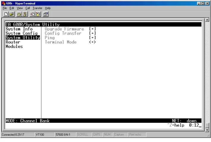
YSTEMU
TILITYS
YSTEMU
TILITY>U
PGRADEF
IRMWARES
YSTEMU
TILITY>U
PGRADEF
IRMWARE>T
RANSFERM
ETHODUpdates firmware when Total Access 600R enhancements are released. Two transfer methods are available for use in updating the Total Access 600R.
The two methods for upgrading are XMODEMandTFTP.TFTP requires a TFTP server running on the network. The Total Access 600R starts a TFTP client function which gets the upgrade code from the TFTP server. Selecting XMO-DEM will load the upgrade code through theCRAFT port using any PC terminal emulator with xmodem capability. The factory default is TFTP.
S
YSTEMU
TILITY>U
PGRADEF
IRMWARE>TFTP S
ERVERA
DDRESSThis is required when the transfer method is TFTP. It is the IP address or domain name (if DNS is configured) of the TFTP server. The factory default is no entry in the TFTP SERVER ADDRESS field.
S
YSTEMU
TILITY>U
PGRADEF
IRMWARE>TFTP S
ERVERF
ILENAMEThis is required when the transfer method is TFTP. It is the case-sensitive file name which contains the upgrade code. The factory default is no entry in the TFTP SERVER FILENAME field.
S
YSTEMU
TILITY>U
PGRADEF
IRMWARE>T
RANSFERS
TATUSThis appears when TFTP is used. It displays the status of the transfer as it happens. Any error or success message will be displayed here.
S
YSTEMU
TILITY>U
PGRADEF
IRMWARE>S
TARTT
RANSFER This activator is used when the configurable items in this menu are complete.S
YSTEMU
TILITY>U
PGRADEF
IRMWARE>A
BORTT
RANSFER Use this activator to cancel any TFTP transfer in progress.S
YSTEMU
TILITY>C
ONFIGT
RANSFERS
YSTEMU
TILITY>C
ONFIGT
RANSFER>T
RANSFERM
ETHODSends a file containing the Total Access 600R configuration to a PC connected to the CRAFT port using XMODEM protocol or to a file on a TFTP server using the TFTP protocol.
CONFIG TRANSFER also lets you save the Total Access 600R configuration as a backup file, so you can use the same configuration with multiple Total Access 600R units. In addition, CONFIG TRANSFER can retrieve a configuration file from a TFTP server.
To support these transfers, ADTRAN delivers a TFTP program with the Total Access 600R called TFTP Server. You can configure any PC running Microsoft Windows with this software, and store a configuration file.
Only one configuration transfer session (upload or download) can be active at a time.
Displays the method used to transfer the configuration file to or from a server. XMODEM and TFTP are supported.
S
YSTEMU
TILITY>C
ONFIGT
RANSFER>T
RANSFERT
YPE Only BINARY transfers are currently supported from this menu.S
YSTEMU
TILITY>C
ONFIGT
RANSFER>TFTP S
ERVERIP A
DDRESSSpecifies the IP address of the TFTP server. Get this number from your system administrator. If using the ADTRAN Utilities TFTP server, this number appears in the TFTP server status window. The factory default value is 0.0.0.0.
S
YSTEMU
TILITY>C
ONFIGT
RANSFER>TFTP S
ERVERF
ILENAMEDefines the name of the configuration file that you transfer to or retrieve from the TFTP server. The default name is
ta600.cfg, but you can edit this name.
S
YSTEMU
TILITY>C
ONFIGT
RANSFER>C
URRENTT
RANSFERS
TATUS Indicates the current status of the update.S
YSTEMU
TILITY>C
ONFIGT
RANSFER>P
REVIOUST
RANSFERS
TATUS Indicates the status of the previous update.S
YSTEMU
TILITY>C
ONFIGT
RANSFER>L
OADANDU
SEC
ONFIGRetrieves the configuration file specified in the TFTP SERVER FILENAME field from the server. To start this command, enter Y to begin or enter N to cancel.
S
YSTEMU
TILITY>C
ONFIGT
RANSFER>S
AVEC
ONFIGR
EMOTELYBefore using the TFTP method for CONFIG TRANSFER, the Total Access 600R should have a valid IP address, subnet mask, and default gateway (if required).
S
YSTEMU
TILITY>P
INGS
YSTEMU
TILITY>P
ING>S
TART/S
TOP Activator to start and cancel a ping test.S
YSTEMU
TILITY>P
ING>H
OSTA
DDRESSIP address or domain name (if DNS is configured) of device to receive the ping. The factory default is no entry in the host address field.
S
YSTEMU
TILITY>P
ING>S
OURCEA
DDRESSSelects whether the ping packet should use the interface address or the NAPT (if that interface uses NAT) as the source address of the ping packet. This is the address that is used for ICMP requests. Interface means it will use the IP address associated with the WAN for outgoing packets and the Ethernet IP address for ICMP requests made on the LAN. NAPT address will replace the WAN IP address with the NAPT address for outgoing ICMP requests. Default is
INTERFACE.
S
YSTEMU
TILITY>P
ING>S
IZE(40-1500)
Total size of the ping to send. Range is 40 to 1500 bytes. The default is 64.
S
YSTEMU
TILITY>P
ING>#
OFP
ACKETSTotal packets to send every 2 seconds. Setting this to 0 allows the client to ping continuously. The default is1.
S
YSTEMU
TILITY>P
ING># T
RANSMITSTotal packets sent (read only).
S
YSTEMU
TILITY>P
ING># R
ECEIVES Total packets received (read only).S
YSTEMU
TILITY>P
ING>%L
OSSPercentage loss based on ping returned from host (read only).
S
YSTEMU
TILITY>T
ERMINALM
ODEThe terminal mode gives the user a command-line prompt. From this prompt, you can: • Perform a reset with the command “reset”
• Perform a factory restore with the command “factory_reset”
• Configure the unit. The Total Access 600R has the ability to download a text file which contains the configuration of the entire unit. This configuration may then be altered in a text editor, and then uploaded to that same or any other Total Access 600R.
• Debug and troubleshooting. This function would be carried out with the assistance of ADTRAN Technical Support.
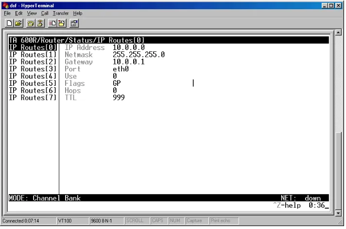
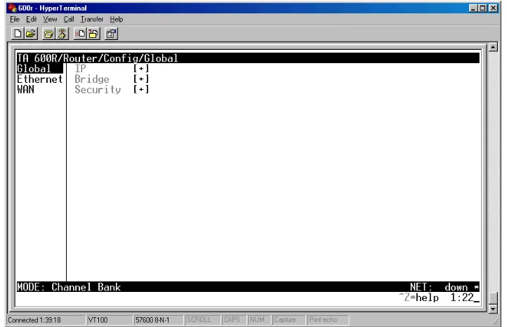
R
OUTERM
ENUSUse the ROUTER/CONFIGURATION menu (Figure 6) to access the GLOBAL, ETHERNET, and WAN menus.
Figure 6. Router/Configuration Menu
R
OUTER>C
ONFIGR
OUTER>C
ONFIG>G
LOBALR
OUTER>C
ONFIG>G
LOBAL>IP
This parameter is used for general IP configuration. Mode
This item controls the GLOBAL option for IP routing. The choices are ON and OFF. The default is ON. Static Routes
Use this menu to enter static routes to other networks
.
DHCP Server
Use this menu to set up the DHCP server.
DNS
Enter the 600R's domain name and the DNS servers in this menu.
ACTIVE Adds this static route entry to the IP routing table when set to YES and removes it (if it was previously added) if set to NO. Default is YES. IP ADDRESS The IP address of the host or network address of the device being routed
to. Default is 0.0.0.0.
SUBNET MASK Determines the bits in the previous IP address that are used. If this is to be a host route, it must be set to all ones (255.255.255.255). Default is 0.0.0.0.
GATEWAY The IP address of the router to receive the forwarded IP packet. Default is
0.0.0.0.
HOPS The number of router hops required to get to the network or host. Maximum distance is 16 hops. Default is 1.
PRIVATE When set to NO, the 600R will advertise this static route using RIP. Setting to YES means that the route is kept private. Default is NO.
DHCP MODE When set to ON, the 600R acts as a DHCP server and will dynamically assign IP, network mask, default gateway, and DNS addresses to any device which transmits a broadcast DHCP request. The addresses as-signed are based on the 600R’s own IP address and will be within the same network. Default is OFF.
DHCP RENEWAL TIME
(HOURS)
The number of hours that the DHCP server should allow the device before it is required to send a new DHCP request. The range is 0-255. The default is 15 hours, and 0 represents an infinite lease.
DOMAIN NAME Text string used to represent the domain name used by the Total Access 600R.
SERVER 1 First server to which domain name requests are sent. Default is 0.0.0.0.
UDP Relay
This menu configures the 600R to act as a UDP relay agent for applications requiring a response from UDP hosts that are not on the same network segment as their clients.
R
OUTER>C
ONFIG>G
LOBAL>B
RIDGEThe BRIDGE menu is used to set up the bridge parameters for the 600R. The bridging function runs at the Media Access Control (MAC) level which allows any protocol packets that run over Ethernet to be for-warded. Bridging can run concurrently with IP. However, when IP routing is active, IP packets (which include ARP packets) are not bridged.
Mode
This is used to enable the bridge function. Default is OFF. Address Table
The 600R automatically maintains a table of MAC addresses detected and associates those addresses with the LAN or WAN port from which they were received.
R
OUTER>C
ONFIG>G
LOBAL>S
ECURITYMODE When this option is set to ON, the 600R will act as a relay agent. Default is OFF.
UDP RELAY LIST Up to four relay destination servers can be specified in this list.
RELAY ADDRESS This is the IP address of the server that will receive the relay packet. Default is 0.0.0.0
UDP PORT TYPE The choices are STANDARD (def) and SPECIFIED. The following standard UDP protocols are relayed when set: DHCP, TFTP, DNS, NTP (Network Time Protocol, port 123), NBNS (NetBios Name Server, port 137), NBDG (NetBIOS Datagram, port 138), and BootP. When SPECIFIEDis set, the UDP port (1 to 65535) can be specified in the UDP Port columns (up to three per server).
UDP PORT 1, 2, 3 Used for specifying UDP ports to be relayed. These fields only apply when UDP PORT TYPE is set to SPECIFIED. Default is 0.
AGING (0-65535) The maximum time an idle MAC address remains in the table before being removed. The value is in minutes. Range is 0 - 65535. Default is 5.
Radius Server
The parameters for the RADIUS server are configured in this menu. The RADIUS server can be used for authenticating a PPP peer (if defined under SECURITY/AUTHENTICATION) and for Telnet server ses-sions.
PPP
The PPP peer can be authenticated using three standard methods: PAP (Password Authentication Proto-col), CHAP (Challenge Handshake Protocol) and EAP (Extensible Authentication Protocol). The strength of the authentication is determined in the order EAP, CHAP, followed by PAP, where EAP is the strongest and PAP is the weakest. PAP is a clear-text protocol, which means it is sent over the PPP link in a readable format. Care must be taken not to allow highly sensitive passwords to become com-promised using this method. CHAP and EAP use a one-way hashing algorithm which makes it virtually impossible to determine the password. EAP has other capabilities which allow more flexibility than CHAP. The following selections are possible:
PRIMARY SERVER This is the IP address of the first RADIUS server that the Total Access 600R should attempt to communicate with when authenticating a PPP peer. Default is 0.0.0.0.
SECONDARY SERVER This is the IP address of the back-up RADIUS server that the 600R should attempt to communicate with when the primary server does not respond. Default is 0.0.0.0.
UDP PORT This is the UDP port that the 600R should use when communicating with the RADIUS server. The default is 1645, which is the commonly used port.
SECRET The RADIUS server and 600R share this text string. It is used by the
RADIUS sever to authenticate the 600R, the RADIUS client. The factory default is not to use a secret.
RETRY COUNT (1-10) This is the number of times the 600R should send a request packet to the RADIUS server without a response before giving up. If the number of attempts to communicate with the primary server is equal to the retry count, the secondary server (if defined) is tried. If the secondary server does not respond within the retry count, the PPP peer (or Telnet session) is not authenticated and is dropped. The default is 5.
PAP, CHAP, OR EAP The 600R will ask for EAP during the first PPP LCP negotiation and allow the PPP peer to negotiate down to CHAP or PAP.
CHAPOR EAP (DEF) The 600R will ask for EAP during the first PPP LCP negotiation and allow the PPP peer to negotiate down to CHAP but not PAP.
Filter Defines
The 600R can filter packets based on certain parameters within the packet. The method used by the 600R allows the highest flexibility for defining filters and assigning them to a PVC or PPP link. The fil-ters are set up in two steps: (1) defining the filter types, and (2) applying them to a list under the PVC or PPP configuration. This menu is used to define the individual filter defines based on packet type.
MAC FILTER DEFINES
The MAC filter is applied to bridge packets only. Bridge packets which are forwarded by the bridge functionality of the Total Access 600R are defined here. Up to 32 MAC defines can be specified.
PATTERN FILTER DEFINES
The pattern filter is applied to bridge packets only. That is any packet which is forwarded by the bridge functionality of the Total Access 600R. Up to 32 pattern defines can be specified.
The FILTER DEFINES option applies to both Frame Relay and PPP applications.
NAME Identifies the filter entry. Default is no entry in name field.
SRC ADDR 48-bit MAC source address used for com-parison. (hexadecimal format) Default is
00:00:00:00:00:00.
SRC MASK Bits in the MAC source address which are compared. (hexadecimal format) Default is 00:00:00:00:00:00.
DEST ADDR 48-bit MAC destination address used for comparison. (hexadecimal format) Default is 00:00:00:00:00:00.
DEST MASK Bits in the MAC destination address used for comparison. (hexadecimal format) Default is 00:00:00:00:00:00.
TYPE 16-bit type field used for comparison. (hexadecimal format) Default is 00:00.
TYPE MASK Bits in the type field used for comparison. (hexadecimal format) Default is 00:00.
NAME Identifies the filter entry. Default is no entry in name field.
IP FILTER DEFINES
The IP filter defines apply to any IP packet, whether it is routed or bridged. Up to 32 IP defines can be specified.
NAME Identifies the filter entry. Default is no entry in name field.
SRC ADDR IP address compared to the source address (dotted decimal format) Default is 0.0.0.0.
SRC MASK Bits which are used in the source comparison. (dotted deci-mal format) Default is 0.0.0.0.
DEST ADDRESS IP address compared to the destination address (dotted
dec-imal format). Default is 0.0.0.0.
DEST MASK Bits which are used in the destination comparison. (dotted decimal format) Default is 0.0.0.0.
SRC PORT IP source port number used for comparison Range: 0 to 65535. (decimal format) Default is 0.
SRC PORT COMP Type of comparison that is performed. Default is none.
= means ports equal to
not = means port not equal to
> means port greater than
< means port less than
None - means the source port is not compared
DEST PORT IP destination port number used for comparison Range: 0 to 65535. (decimal format) Default is 0.
DEST PORT COMP Type of comparison that is performed. Default is none.
= means ports equal to
not = means port not equal to
> means port greater than
< means port less than
None - means the destination port is not compared
PROTO PORT Protocol used for comparison. Range: 0 to 255. (decimal format) Default is 0.
PROTO PORT COMP Type of comparison that is performed. Default is none.
= means protocols equal to
not = means protocols not equal to
> means protocols greater than
< means protocols less than
R
OUTER>C
ONFIG>E
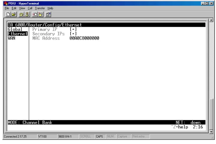
THERNETUse the ETHERNET menu (Figure 8) to configure the Ethernet port on the 600R.
Figure 8. Ethernet Menu
R
OUTER>C
ONFIG>E
THERNET>P
RIMARYIP
This is used to setup the IP address for the LAN on the 600R. IP Address
The IP address assigned to the 600R's Ethernet port is set here. This address must be unique within the network. Default is 10.0.0.1.
Subnet Mask
This is the IP network mask that is to be applied to the 600R's Ethernet port. Default is 255.255.255.0. TCP ESTAB Yes - only when TCP established
No - only when TCP not established
Proxy ARP
This feature allows the network portion of a group of addresses to be shared among several physical network segments. The ARP protocol provides a way for devices to create a mapping between physical addresses and logical IP addresses. Proxy ARP makes use of this mapping feature by instructing a router to answer ARP requests as a “proxy” for the IP addresses behind one of its ports. The device which sent the ARP request will then correctly assume that it can reach the requested IP address by sending packets to the physical address that was returned. This technique effectively hides the fact that a network has been (further) subnetted. If this option is set to YES, when an ARP request is received on
the Ethernet port the address is looked up in the IP routing table. If the forwarding port is not on the Ethernet port and the route is not the default route, the Total Access 600R will answer the request with its own hardware address. Default is YES.
R
OUTER>C
ONFIG>E
THERNET>S
ECONDARYIP
SThis allows the Total Access 600R to specify additional IP addresses and networks on its Ethernet. The max-imum number of entries is 10.
IP Address
This is the second IP address the 600R will respond to on the Ethernet. Default is 0.0.0.0. Subnet Mask
This is the mask for the network. Default is 255.255.255.0.
R
OUTER>C
ONFIG>E
THERNET>MAC A
DDRESSThis is a read-only field which displays the unique MAC address programmed at ADTRAN.
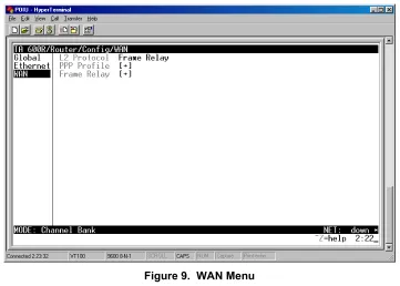
R
OUTER>C
ONFIG>WAN
Use the WAN menu (Figure 9) to configure WAN settings on the 600R.
MODE Enables or disables RIP. Default is OFF.
PROTOCOL Specifies the RIP protocol. Choices are V1 (RIP version 1) or
V2 (RIP version 2). Default is V1.
METHOD Specifies the way the RIP protocol sends out its
advertise-ments. Choices are given below.
NONE All routes in the router table are advertised with no modification of the metrics.
SPLIT HORIZON Only routes not learned from this circuit are adver-tised.
POISON REVERSE
(DEF)
All routes are advertised, but the routes learned from this port are “poisoned” with an infinite met-ric.
DIRECTION Allows the direction at which RIP advertisements are sent and
listened to be specified.
TX AND RX (DEF) RIP advertisements are periodically transmitted and are listened to on this port.
TX ONLY RIP advertisements are periodically transmitted but are not listened to on this port.
RX ONLY RIP advertisements are listened to on this port, but are not transmitted on this port.
Figure 9. WAN Menu
R
OUTER>C
ONFIG>WAN>L2 P
ROTOCOLDisplays the current L2 protocol. Choices are PPP, FRAME RELAY, and AUTO DETECT. Default is FRAME
RELAY.
R
OUTER>C
ONFIG>WAN>PPP P
ROFILEThe Total Access 600R uses the WAN/PPP profile to specify the profile used when connected using PPP. Authentication
The authentication menu contains the required parameters for the authentication of the PPP peer and for being authenticated by the PPP peer. Authentication is applied between the Total Access 600R and the PPP peer as follows:
TX METHOD
This parameter specifies how the Total Access 600R is to be authenticated by the PPP peer. There are four possible selections. Default is PAP, CHAP, or EAP.
NONE The connection will not allow the PPP peer to authenticate it.
TX USERNAME
This is the username that is used when being authenticated by the PPP peer. You can enter up to 31 characters in this field. Default is no entry in the TX username field.
TX PASSWORD
This is the password or secret that is used when being authenticated by the PPP peer. You can enter up to 15 characters in this field. Default is no password.
RX USERNAME
This is the username used to authenticate the PPP peer. You can enter up to 31 characters in this field. Default is no entry in the RX username field.
RX PASSWORD
This is the password or secret that is used to authenticate the PPP peer. You can enter up to 15 charac-ters in this field. Default is no password.
IP
The IP menu contains the parameters for exchanging IP data with the PPP peer.
MODE
Setting to ON (def) will permit this connection profile to negotiate PPP IPCP with the PPP peer for routing of IP packets. Choices are OFF and ON.
NAT
The Total Access 600R can perform Network Address Translation. This feature is most widely used when connecting to the Internet. The Ethernet network can consist of private network numbers. When this profile is connected, all IP addresses on the Ethernet side are translated into the one real IP address negotiated with the PPP peer (ISP). Multiple stations on the Ethernet side can access the Internet simultaneously.
.
PORT TRANSLATION By enabling port translation, IP packets are modified as they pass through this interface. During transmission, private addresses are translated into a single public (NAPT) IP address. Incoming packets are translated from the public to private address based on the protocol port numbers. Once enabled, you must set up NAT for use. Default is DISABLED. When disabled, the unit will route across the connection normally.
PUBLIC IP ADDRESS
MODE
This option is only available when NAT PORT TRANSLATION is en-abled. The port translation requires at least a single real IP ad-dress for translating. This value can use the IP assigned to the interface (or assigned via layer 2 protocol like PPP), obtained us-ing DHCP client, or statically specified on this menu. If the ad-dress cannot be learned, then it must be specified in order for the translation to work. Choices are INTERFACE, SPECIFIED, and DHCP CLIENT. Default is INTERFACE.
PUBLIC IP ADDRESS This is the specified address used for NAT. This option is only available when NAT PORT TRANSLATION is enabled and the
PUBLIC
ADDRESS MODE
This option is only available when NAT PORT TRANS -LATION is enabled. The public IP address used for this translation entry can be the NAPT IP address assigned to the link or can be specified. You specify an address to direct packets with certain protocols to different servers. Choices are NAPT ADDR and SPECIFIED.
Default is NAPT ADDR. PUBLIC
ADDRESS
This option is only available when NAT PORT TRANS -LATION is enabled and the PUBLIC ADDRESS MODE is set to SPECIFIED. Default is 0.0.0.0.
PROTOCOL
MODE
This option is only available when NAT PORT TRANS -LATION is enabled. The upper layer protocol that is to be monitored for translation. For TCP and UDP, a port number must also be specified. Choices are TCP; UDP; ICMP; ANY (TCP, UDP, OR ICMP); ALL; SPECIFIED; and NONE. Default is NONE.
PROTOCOL This option is only available when NAT PORT TRANS
-LATION is enabled and PROTOCOL MODEis set to SPECI-FIED. Default is 0 (decimal).
PROTOCOL TYPE This option is only available when NAT PORT TRANS -LATION is enabled and PROTOCOL MODEis set to SPECI-FIED. This is a read-only field.
PUBLIC PORT
MODE
This option is only available when NAT PORT TRANS -LATION is enabled and PROTOCOL MODEis set to either
TCP or UDP.
The public destination port associated with this entry can be specified to add more control over certain types of traffic. Choices are SPECIFIED and ANY PORT. The
default, ANY PORT, covers all port types.
PUBLIC PORT This option is only available when NAT PORT TRANS -LATION is enabled and PUBLIC PORT MODEis set to
SPECIFIED. However, it will not be available if PROTO -COL MODEis set to ICMP; ANY (TCP, UDP, OR ICMP); ALL; SPECIFIED; or NONE. Default is 0
(dec-imal).
PUBLIC PORT
TYPE
This option is only available when NAT PORT TRANS -LATION is enabled and PUBLIC PORT MODEis set to
read-PRIVATE
ADDRESS
MODE
This option is only available when NAT PORT TRANS
-LATION is enabled. The private IP address can be speci-fied to steer certain protocols and ports to specific servers in the private network. Likewise, internal hosts can be steered to certain servers on the public network. A new request from the public network matching this entry’s public parameters will be dropped if this mode is set to ANY INTERNAL. Choices are SPECIFIED and ANY INTERNAL. Default is ANY INTERNAL.
PRIVATE
ADDRESS
This option is only available when NAT PORT TRANS -LATION is enabled and PRIVATE ADDRESS MODEis set to
SPECIFIED. Default is 0.0.0.0. PRIVATE
PORT MODE
This option is only available when NAT PORT TRANS
-LATION is enabled.However, it will not be available if
PROTOCOL MODEis set to ICMP; ANY (TCP, UDP, OR ICMP); ALL; SPECIFIED or NONE.
The private destination port associated with this entry can be specified to add more control over certain types of traffic. Leave as ANY PORT to cover all port types.
Choices are ANY PORT and SPECIFIED. Default is ANY PORT.
PRIVATE
PORT
This option is only available when NAT PORT TRANS
-LATION is enabled and the PRIVATE PORT MODEis set to
SPECIFIED.However, it will not be available if PROTO
-COL MODEis set to ICMP; ANY (TCP, UDP, OR ICMP); ALL; SPECIFIED or NONE. Default