ISSN (Print) : 2320 – 3765 ISSN (Online): 2278 – 8875
I
nternational
J
ournal of
A
dvanced
R
esearch in
E
lectrical,
E
lectronics and
I
nstrumentation
E
ngineering
(A High Impact Factor, Monthly, Peer Reviewed Journal) Website: www.ijareeie.com
Vol. 7, Issue 6, June 2018
A
Real Time Data Driven Algorithm for
Industrial Fault Diagnosis using Ethernet
Based
Systems
Pranita A. Raut1 , Uttam L. Bombale2
PG Student, Department of Electronics Technology, Shivaji University, Kolhapur, Maharashtra, India1
AssociateProfessor, Department of Electronics Technology, Shivaji University, Kolhapur, Maharashtra, India2
ABSTRACT: Nowadays fault detection plays an important role in high cost and safety critical processes. Early
detection of faults can help to avoid normal event progression. Fault detection can be achieved through various means. Fault diagnosis consists of all actions taken for fault recognizing, fault locating and root cause identification. For networking, Ethernet is suitable to act as the backbone to connect multiple domains and also for interworking within domains. Hence this paper proposes a real time data driven algorithm for industrial fault diagnosis and localization of an Ethernet based systems. This paper presents the development of a new real time diagnosis algorithm that continuously monitors all the electronic equipments and shows the indication accordingly. The proposed algorithm detects the abnormalities and find the root causes. Finally the results obtained by the implementation of proposed algorithm using Ethernet have been presented.
KEYWORDS: Fault diagnosis, Ethernet, Engineering applications in industrial electronic equipments.
I.INTRODUCTION
ISSN (Print) : 2320 – 3765 ISSN (Online): 2278 – 8875
I
nternational
J
ournal of
A
dvanced
R
esearch in
E
lectrical,
E
lectronics and
I
nstrumentation
E
ngineering
(A High Impact Factor, Monthly, Peer Reviewed Journal) Website: www.ijareeie.com
Vol. 7, Issue 6, June 2018
II.PROPOSED METHOD
Methodology as given below is implemented in the proposed work:
Here the PIC controller is used for the interface with ethernet card which converts protocol into TCP LAN. The system is very useful in complex machinery process and control system to diagnose the system for multiple test
points using remote real time data monitoring and controlling. All sensing part is monitored by controller and information is send via network interface card using TCP frame using protocols which is displayed on the laptop. The PIC controller is used to monitor the main industrial machine parameters and send accurate information with diagnosis and also locate the faults in real time system using real time clock of PC. Ethernet acts as a backbone of the entire network. In the OSI model, Ethernet technology operates at the physical and data link layers - Layers One and Two respectively. Ethernet supports all popular network and higher-level protocols, principally TCP/IP. Data sent over the Ethernet exists in the forms of frames. An Ethernet frame contains a header, a data section, and a footer having a combined length of no more than 1518 bytes. The Ethernet header contains the addresses of both the intended recipient and the sender.Hence the proposed design for the fault diagnosis system uses Ethernet instead of traditional Controller Area Network (CAN) and it does not need a scan tool for diagnosis. This system will inform the exact place of fault occurrence in the electronic equipments to the user without the need of trouble codes. Hence one can diagnose on his own without the help of technicians and service center.
ISSN (Print) : 2320 – 3765 ISSN (Online): 2278 – 8875
I
nternational
J
ournal of
A
dvanced
R
esearch in
E
lectrical,
E
lectronics and
I
nstrumentation
E
ngineering
(A High Impact Factor, Monthly, Peer Reviewed Journal) Website: www.ijareeie.com
Vol. 7, Issue 6, June 2018
The entire system has one PIC 16F877A microcontroller, an Ethernet card, laptop, and Ethernet cables. The PIC controller and Ethernet card acts as an embedded integrated server and laptop acts as a client. This follows the server-client architecture, the PIC controller being the server and it has an LCD display associated with it. The serial data from the microcontroller is converted into Ethernet packet data by using the Ethernet card. The Ethernet cable from this interface unit is connected to laptop. The transmission control protocol is used here, as we have an option of acknowledgement in it.
III.SYSTEM IMPLEMENTATION
Design of faults in parameters, notification of sudden changes to the driver and indication regarding the reason for the fault are included in the setup.
In this paper, we are going to diagnose following electronic equipments.
AC FUSE:
Here the fuse is connected to primary mains side applying 230 volt ac signal. The phase is connected in series with the fuse. The output is same which is connected to series resistance of 2 watt which drops mains voltage & current in circuit. The capacitor holds & boost the current compensation which was drop by resistance. The output is connected to bridge rectifier which converts ac to dc voltage with suitable resistance to connect with optocoupler which is nothing but isolate mains voltage to circuit voltage for TTL logic.
The MCT2E isolator has internal led which is on & focused on photo transistor which conducts as light fall on base & thus we get digital o/p in form of 1 & 0 the o/p is connected to 40106 Schmitt trigger with not gate which inverts the state . Also give pulse in sharp rise & fall to recognize the output change.
Assume if mains =1 ( 230v) then optocoupler led =on, collector of phototransistor = 0v , Schmitt trigger o/p = 1 ,so we get logic 1 to interface for microcontroller.
Assume if mains fail =0, optocoupler led = off, ,collector of phototransistor = 1v , Schmitt trigger o/p = 0 ,so we get logic 0 to interface for microcontroller.
In this way we can detect AC mains failure.
DC FUSE:
This circuit is used to detect blown DC fuse ,so we can identify the status of fuse. Basically circuit is built using Opto-Coupler as it can be used to isolate I/P & O/P stages .
1. I/P = 1, LED of Optocoupler = On, collector of phototransistor = 0,
Schmitt trigger I/P = 0, Schmitt trigger o/P = 1 this is feed to PIC controller I/P port. ( Fuse OK condition ) 2. I/P = 0, LED of Optocoupler = Off, collector of phototransistor = 1,
Schmitt trigger I/P = 1, Schmitt trigger o/P = 0 this is feed to PIC controller I/P port. ( Fuse Blown condition )
PIC controller reads this signal and acts accordingly.
H BRIDGE INVERTER CARD:
This circuit is designed to control the load. The load may be motor or any other load. The load is turned ON and OFF through relay.
For h bridge we have selected full removal of IC instead of gates due to avoid imbalance in the circuit which can damage certain components which can create major faults while testing. So for safety measures we remove IC and balanced the circuit in order to give readings on GUI.
MINIATURE CIRCUIT BREAKER:
ISSN (Print) : 2320 – 3765 ISSN (Online): 2278 – 8875
I
nternational
J
ournal of
A
dvanced
R
esearch in
E
lectrical,
E
lectronics and
I
nstrumentation
E
ngineering
(A High Impact Factor, Monthly, Peer Reviewed Journal) Website: www.ijareeie.com
Vol. 7, Issue 6, June 2018
Flowchart of proposed algorithm is as follows:
Define all ports as I/P and O/P Define LCD
Set IP address in laptop with all settings in adapter settings
Check connectivity LAN protocol
Set serial communication with baud rate
Read the status of M1,M2,M3,M4 (different machines)
Read M1 (H bridge circuit) Check O/P of H bridge in the form of byte
Send to ETHERNET
Convert serial protocol to TCP protocol on specific IP address
Send via RJ 45 cable
Read Winsock drivers Read VB 2010 drivers and link file in exe main files
ISSN (Print) : 2320 – 3765 ISSN (Online): 2278 – 8875
I
nternational
J
ournal of
A
dvanced
R
esearch in
E
lectrical,
E
lectronics and
I
nstrumentation
E
ngineering
(A High Impact Factor, Monthly, Peer Reviewed Journal) Website: www.ijareeie.com
Vol. 7, Issue 6, June 2018
Figure (2): Flowchart
Repeat the same procedure for different machines e.g. AC fuse (M2), DC fuse (M3), switch circuit (M4) and MCB for fault diagnosis.
IV. RESULTS
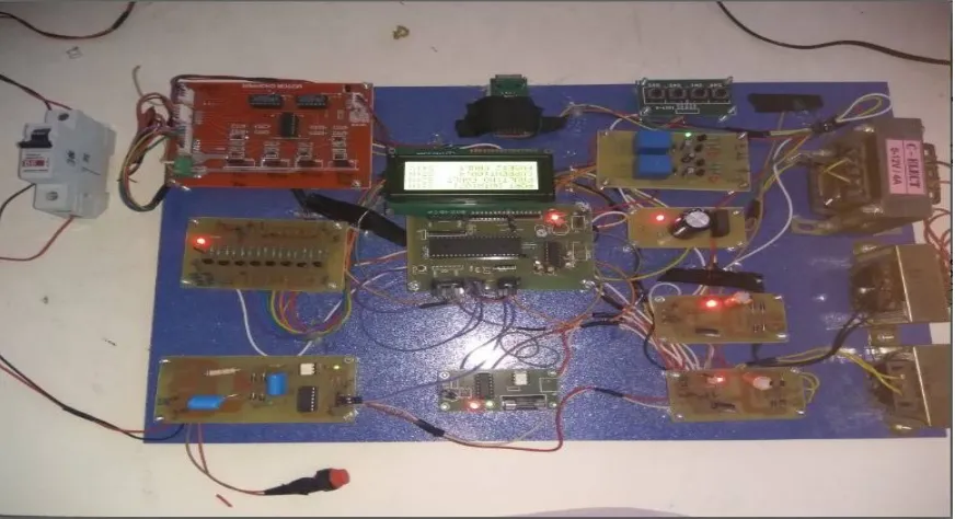
The lab setup for proposed algorithm is as follows:
Figure (3): System Setup
Here the industrial application panel refers to as the several electronic equipments that is AC fuse, DC fuse, H bridge inverter card, MCB etc. Once the equipment is connected to the Ethernet network, it can be monitored and controlled through the PIC controller and displays the results on Laptop.
Display value in the text box with comments
ISSN (Print) : 2320 – 3765 ISSN (Online): 2278 – 8875
I
nternational
J
ournal of
A
dvanced
R
esearch in
E
lectrical,
E
lectronics and
I
nstrumentation
E
ngineering
(A High Impact Factor, Monthly, Peer Reviewed Journal) Website: www.ijareeie.com
Vol. 7, Issue 6, June 2018
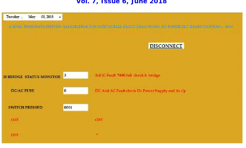
Figure (4): GUI
This GUI screen indicates that there is some fault in H bridge inverter card, AC fuse and DC fuse and also shows that all switches are off. In this way we can diagnose the faults in the electronic equipments by monitoring the system.
V.CONCLUSION
This paper presents the monitoring of different electronic equipments and the challenges involved in developing such an algorithm. A typical setup for implementing the proposed real time data driven monitoring algorithm has been also discussed. This algorithm is easy and cost effective to implement and it does not need the past performance and health history of different parameters for monitoring.
ACKNOWLEDGEMENT
Authors are thankful to Shivaji University, Department of Technology, Kolhapur, India (Maharashtra), for providing necessary facilities for completion of this research.
REFERENCES
[1] Saugata S. Biswas, Anurag K. Srivastava,and Dave Whitehead, “A Real Time Data-Driven Algorithm for Health Diagnosis and Prognosis of a Circuit Breaker Trip Assembly” IEEE transactions on industrial electronics 2014.
[2] Varun C. and Kathiresh M., “Automotive Ethernet in On-Board Diagnosis (Over IP) & In-Vehicle Networking” International Conference on Embedded Systems 2014.
[3] Leiming Zhang, and Qing Chang, “Intermittent Connection Fault Diagnosis for CAN Using Data Link Layer Information” IEEE Transactions on Industrial Electronics 2016.
[4] Supriya Kelkar and Raj Kamal, “Adaptive Fault Diagnosis Algorithm for Controller Area Network” IEEE Transactions on Industrial Electronics, vol. 61, no. 10, October 2014.
[5] Bilal Akin, Seungdeog Choi, Umut Orguner, and Hamid A. Toliyat, “A Simple Real-Time Fault Signature Monitoring Tool For Motor-Drive-Embedded Fault Diagnosis Systems” IEEE Transactions on Industrial Electronics 2011.
ISSN (Print) : 2320 – 3765 ISSN (Online): 2278 – 8875
I
nternational
J
ournal of
A
dvanced
R
esearch in
E
lectrical,
E
lectronics and
I
nstrumentation
E
ngineering
(A High Impact Factor, Monthly, Peer Reviewed Journal) Website: www.ijareeie.com
Vol. 7, Issue 6, June 2018
[8] Kai Muller, Till Steinbach, Franz Korf, and Thomas C. Schmidt, “A Real-time Ethernet Prototype Platform for Automotive Applications” IEEE International Conference on Consumer Electronics 2011.
[9] Shantanu Dutt, Vinay Verma, and Vishal Suthar, “Built-in-Self-Test of FPGAs With Provable Diagnosabilities and High Diagnostic Coverage With Application to Online Testing” IEEE Transactions on Computer-aided design of integrated circuits and systems 2008.
[10] Z. Gao, H. Saxen, and C. Gao, “Special Section On Data-Driven Approaches For Complex Industrial Systems,” IEEE Transactions on Industrial Information, 2013.
[11] B. Mirafzal,“Survey Of Fault-Tolerance Techniques For Three-Phase Voltage Source Inverters,” IEEE Trans. Ind. Electron., vol. 61, no. 10, pp. 5192–5202, Oct. 2014.
[12] Z. Gao, C. Cecati, and S. X. Ding, “A Survey Of Fault Diagnosis And Fault-Tolerant Techniques—Part I: Fault Diagnosis With Model-Based And Signal-Based Approaches,” IEEE Trans. Ind. Electron., vol. 62, no. 6, pp. 3757–3767, Jun. 2015.
[13] I. Albizu, A. Tapia, J. R. Saenz, A. J. Mazon, I. Zamora, "Online Stator Winding Fault Diagnosis In Induction Generators For Renewable Generation," IEEE Electrotechnical Conference., pp. 1017-1020, May 2004.
[14] A. Bouzida, O. Touhami, R. Ibtiouen, A. Belouchrani, M. Fadel, A. Rezzoug, "Fault Diagnosis in Industrial Induction Machines Through Discrete Wavelet Transform” IEEE Trans. Ind. Electron., vol. 58, no. 9, pp. 4385 - 4395, Sept 2011.
[15] Andreas Kern and Thilo Streichert, “An Automated Data Structure Migration Concept - From CAN to Ethernet/IP in Automotive Embedded Systems” (CAN over IP).
[16] M. Rahmani, M. Pfannenstein, E. Steinbach,G. Giordano, and E. Biersack, "Wireless Media Streaming over IP-based In-Vehicle Networks.", IEEE International Conference on Communications Workshops 2009, pp. 1-6 June 2009.