SVPWM Based BLDC Close loop drive
Milankumar Ghevariya1, Dr. Pramod S. Modi2
Student, M S University of Baroda, Gujarat, India
Associate Professor, Department of Electrical Engineering, M S University of Baroda, Gujarat, India
ABSTRACT: A brushless dc motor is categorized by high efficiency with good life time. Designed Bldc motor requires accurate speed and to recover rapidly from any turbulences for high performance, and sensitive to motor parameter variants.Many different speed controllers are widely used to run the motor for proper reference speed. In this present work, the current control technique are use to control the speed and position of BLDC motor. This method plays an important role, in the hardware implementation of position and speed control of BLDC motor. the error signals of currents achieved are fed to the rotor reference frame transformation (abc–dq) which develops the d-q currents. The position and speed of BLDC motor are control using d-q voltage which obtained from d-q current and fed to space vector PWM modulator.
KEYWORDS::PI current control, BLDC motor, Space vector PWM
I.INTRODUCTION
In recent years, smart control technology ,permanent magnet resources, computer technology, and power electronics technology, mostly the power switch component technology has been fast development, and it rested an important substance for the research and manufacture of the permanent magnet brushless DC motor (BLDCM). The BLDCM widely used in the servo mechanism , field of CNC machine tool, robots, because of its small size, control of high accuracy, easy maintenance. The modelling, simulation and analysis of a BDCM drive. The simulation included the real-time model ,state space model of the motor and speed controller of the inverter switches. Specific attention wasfunded to the motor large- and small-signal dynamics and motor torque pulsations. (1) In current control technique, the d-q current are drive using rotor reference frame transformation (abc–dq) error signals of currents obtained are fed to the which drive the d-q currents. The position and speed of BLDC motor are control using d-q voltage which obtained from d-q current and fed to space vector pwm modulator.[3] This paper realisedMatlabsimulink models Ofthe different control techniques like Sinusoidal Pulse Width Modulation (SPWM) and Space Vector Pulse Width Modulation (SVWM) delivered with proportional Integral (PI).[7]
A tuning methods of a PI speed controller for separatelyexcited Direct current motor is presented, based on Empirical Ziegler-Nichols tuning formula and improved Ziegler-Nichol PI tuning formula. Both these methods are compared on the basis of output response, minimum overshoot, and minimum settling time for speed demand application of BLDC motor.[10] as BLDC motor have a Trapezoidal BEMF so a many rotor referenceframe technique is not valid in this motor but in this paper we can apply the technique of abc -dq transformation in current control. when compared to other techniques this technique is advantages like Speed and position controller of BLDC motor at lower voltage ratings, high speed at low voltages, and accuracy in position control, reliability with high efficiency and also advantageous for most of the Hardware motor control.
II.PROPOSED MODEL
characterised by its equivalent circuit, which comprises of stator resistance , self-inductance , and a back-emf. Fig.1 show the BLDC motor is an electronic motor and needs a 3-phase inverterto the driving side for feeding
power into the machine and according to the output from the position sensors inverter works as an electronic commutation which completes the switching of bridge.
Fig.2.1 3-phase Voltage Source Inverter with Motor
2.1 Voltage and Current Control PWM
The current and voltage control operation are essentially two modes of the inverter which are feedback (FB) mode and freewheeling mode. In both these modes switching devices are turned on and off for timing basis to controlled the machine current Iav and the machine average voltage Vav. In addition to the commutation function controlling the
switches in PWM modewe control the voltages and currents continuously at the machine terminal
3.Space Vector Pulse Width Modulation
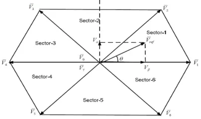
The space vector concept is used for modifying the inverter output voltage. its derivative from rotating magnetic field theory. the output of inverter can be controlled by using 2-phase Vref component which are drive from 3-phase voltages are transformed either in stationary reference frame or synchronous rotating reference frame in 2-phase voltage.
The 3-phase balanced voltages as shown below,
If In 3- phase BLDC motor we apply the three phase balanced voltage ,rotating flux vector is creates in the air gap of the induction machine rotating with a velocity of . Usingthe Clark’s transformation method in stationary reference frame wecan calculated this rotating flux vector magnitude and angle as shown below.
Where,
Real and imaginary parts is separated using the above equation which are
The above equations is present in matrix form which are..
3.2. Implementation Of Space Vector PWM
In three steps We can implemented SVPWM which are 1. Evaluateα , Vd,andVq.
3. Evaluateswitching time of each switching device (S1 TO S6).
3.2.1 Evaluateα andVd , Vq
Using the Clark’s transformation 3-phase voltages are transformed to two phase voltagesin αβ stationary reference framethat is shown in figure.3.2
3.2.2 Calculate T0, T1and T2.
i. CalculateT0,T1 and T2 for sector-1:
In sector-1 the two active voltage vectors and two null vectors are requires to generating a voltage vector Vref at a sampling Tztime. At time T1/Tz interval the active voltage vector V1, at time T2/Tz the active voltage vector V2 are applied, and at a time intervals of T0/Tz and T7/Tz the two null vectors V0 and V7 which are applied respectively.in sector-1 Vref shown in below figure.
Fig 3.3. Calculation VrefIn Sector-1 Calculate Vref Using volt-sec balance equationas follows
Real and imaginary parts Separate from the above equation, then
Real and imaginary parts Separate from the above equation, then
T1 and T2are calculated Using this equations as follows which are
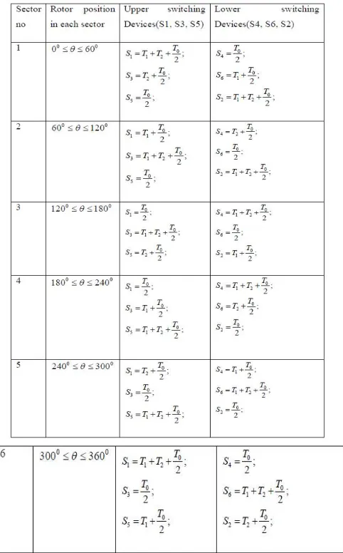
3.2.3 Calculate Switching Time Of Each Switching Device (S1 To S6):
For each cycle have a 7 switching states in each sector is shown in table 3.1.The even sector numbers movements in anti-clockwise direction and odd sector numbers movements in clockwise direction.
IV. CONTROL STRATEGY
4.1 BLDC Motor Current Control Structure
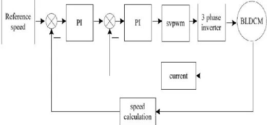
For Hardware implementation ofBLDC motor is an advantage of this control technique. This BLDC drive system consists of PM BLDC motor , Space Vector PWM ,PI speed controller, Current Transformation, , and an MOSFET inverter are modelled and integrated for simulation in the real-time conditions. The block diagram of BLDC Motor control are shown in fig 4.1.
The BLDCM control system has dual closed-loop control that the outer speed loop and innercurrent loop, and uses classic PI control algorithm. The overall system block diagram is shown in Fig 4.1
Fig 4.1 block diagram of BLDC motor control system
In the current closed loop, Using the coordinate transformation of the electrical system the 3-phase current are converted to the system rotatingco-ordinate current is analysis[6,7] formula as, for the feedback current.
Where, iA, iB, iCare phase A,B,C current, id, iqare d-q coordinate component,iα, iβ are α-β coordinate component , θ is
the axis of the rotor and the stator A phase winding axisangle. Using the motor rotation at the whole simulation system determined the Rotor position. Module of inverter is build by the SVPWM control algorithm and control principle. BLDCMuses Permanent Magnet Synchronous Machine motor module from SIMULINK/SIMPOWERSYSTEMS. Inverter takes general inverter bridge of MOSFET device.
4.2 Structure of Speed Control
theON-OFF time of the switching devices in the inverter therefore control the voltage fed to the motor. For industrial use PI controller is the best generally used controller because it is easy to implement.
The below equation is defined the structure of speed controller,
Where,e(t)= Reference speed – Actual speed
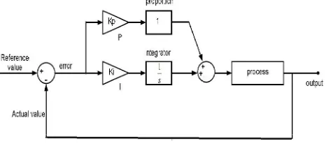
4.3 Introduction about PI Speed Controller.
The error between the reference valueand the actual value is reduces by the Proportional Integral (PI) controller .DC gain of the system increases by the proportional controller, the steady state error of the system reduces by integral
controller . is shown in the Fig 4.2 is show the structure of the PI controller .
Fig. 4.2Closed Loop PI Controller System Equation of PI controller
Where, error e(t) = reference value – actual value
Where,
V. MATLAB SIMULATION OF BLDC MOTOR WITH SVPWM
Fig.5.1 Simulation Model Of BLDC drive
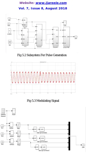
Figure 5.1 shows the Simulink model of BLDC Drive. In fig 5.1 show the Subsystem“SVPWM” employs the implementation of space vector PWM and produce the gate pulse of inverter bridge and is shown in figure 5.2. In fig 5.2 show The block “subsystem1” produce the modulating waveform Tcm1,Tcm2 and Tcm3 is shown in fig 5.3. This modulatingsignal are generate using the equationwhich are implementIn block “subsystem1”.
Fig 5.2 Subsystem For Pulse Generation
Fig 5.3 Modulating Signal
Fig.5.5 Signal of Gate Pulse
5.2. Output waveform for variable speed and constant torque of BLDCM
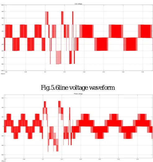
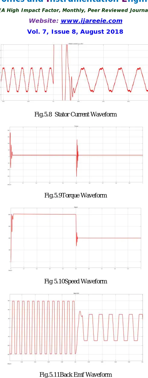
Fig 5.6 ,5.7, 5.8, 5.9,5.10 and 5.11 shows a set of simulated waveforms for the Three-phase BLDC motor fed through two level inverter.
The input voltage Vdc=400v carrier frequency fs = 5000Hz
The speed of motor is change at 2000rpm to 1000rpm and is shown in fig 5.10
Fig.5.6line voltage waveform
Fig.5.8 Stator Current Waveform
Fig.5.9Torque Waveform
Fig 5.10Speed Waveform
VI. CONCLUSION
In hardware implementation of industrial area this control technique have wide range of advantages for BLDC motor. This technique is valid in hardware implementation while using analog to digital converter instead of back EMF zero detector. This paper concludes that, in the current control technique, In this present work, the current control technique are use to control the speed and position of BLDC motor. the error signals of currents achieved are fed to the rotor reference frame transformation (abc–dq) which develops the d-q currents. Using this d-q currents the d-q voltages are obtained and fed to space vector pulse width modulator which controls the position and speed of BLDC motor. By using MATLAB/SIMULINK the technique is simulated and results derived explain that the torque is controlled efficiently with automatic position and speed control with less harmonics in switching of inverter.
REFERENCES
1) P.Pillay and R.Krishnan, “Modeling, simulation, and analysis of permanent-magnet motor drives, part II: The brushless dc motor drive,” IEEE Trans.Ind.Appl.,vol.IA25,no.2,pp.274-279,Mar./Apr.1989.
2) Shivraj Sdudhe Archana G Thosar “ MATHEMATICAL MODELLING AND SIMULATION OF THREE PHASE BLDC MOTOR USING MATLAB/SIMULINK” International Journal of Advances in Engineering & Technology, Nov., 2014. ©IJAET ISSN: 22311963
3) Kota.Chandrika.Naga.Sridivya and Dr. T.Vamsee Kiran ” SPACE VECTOR PWM CONTROL OF BLDC MOTOR” International Conference on Power and Embedded Drive Control (ICPEDC) 978-1-5090-4679-9/17_c 2017 IEEE
4) Abolfazl Halvaei Nisar, Hassan Moghbeli, Ehsan Boloor Kashni, “A low-cost sensorless BLDC motor drive using one-cycle current control strategy” IEEE, 2014,pp. 20-22.
5) K. Wei, C. S. Hu, and Z. C. Zhang, “A novel commutation torque ripple suppression scheme in BLDCM by sensing the DC current,” in 36th IEEE Power Electron. Spec. Conf., 2005, pp. 1259–1263
6) Boyang Hu, Swamidoss Sathiakumar, Yash Shrivastava” 180-Degree Commutation System of Permanent Magnet Brushless DC Motor Drive Based on Speed and Current Control” Second International Conference on Intelligent Computation Technology and Automation © 2009 IEEE 7) Jagraj Singh1, Manpreet Singh “Comparison and Analysis of Different Techniques for Speed Control of Brushless DC Motor using Matlab Simulink”Inte rnational Journal of Engineering Trends and Technology (IJETT) – Volume 38 Number 7- August 2016
8) Carlson, Renato, Michel Lajoie-Mazenc, and J. C. D. S. Fagundes. "Analysis of torque ripple due to phase commutation in brushless DC machines." Industry Applications, IEEETransactions on 28, no. 3 (1992): 632-638.
9) V.Viswabathan, Dr.SJeevananthan, “A Novel Current Controlled Space Vector Modulation Based Control Scheme for Reducing Torque Ripple in Brushless DC Drives”, IJCA,Volume 28, No .2, Aug 2011.