www.ijiset.com
Comparative Analysis of Dual, Quad and Octa
Element Patch Array Antenna
K.Srinivasa Naik1, K.Y.K.G.R.Srinivasu2
1
Department of ECE, Vignan’s Institute of Information Technology, Visakhapatnam, Andhra Pradesh, India
2 Department of ECE, Vignan’s Institute of Information Technology,
Visakhapatnam, Andhra Pradesh, India
Abstract
Antenna engineering and communication systems always compliment with each other. In wireless communicaion systems always an antenna with appreciable performance is a desired one and it should be compact as well as flexible in nature.Rectangular microstrip patch antenna with single element can satisfy the above mentioned criteria, but it is not suitable for the radar communication. In view of the above mentioned fatcs, this endeavor purely concentarates on the design of the antenna array with dual, quad and octa patch by using edge feeding technique in three different methodlogies. The 2, 4 and 8 element antenna array is designed and their characteristics are comapared with each other. The operating frequency for this design hangs around 10GHz. Rogers RT/ Duroid 5880 with a dielectric constant of 2.2 and loss tangent of 0.009 has been choosen as a dielectric material to carry out the design and HFSS is the platform for the implementation.
Keywords: Antenna array, Directivity, Edge fed, Gain, HFSS, Microstrip patch antenna, Rogers RT Duroid.
1. Introduction
An antenna is a transducer that converts the radio frequency fields into alternating currents or vice versa. It also acts as an impedance matching device between the source and load. The equivalent network of a transreceiver can also analyzed in the form of a network which satisifes the basic network theorems.As the antenna is subjected to radiate power to longer distances, it have a falred structure [1-2]. To measure the distance of the ships and to provide navigation at sea shore in marine radars, asymmetrical sum patterns are useful. These patterns are very helpful in point to point commuication. [3-5].
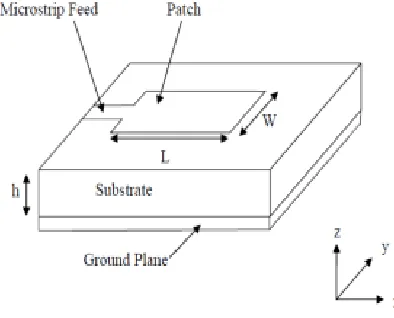
The Microstrip Patch Antenna is a single-layer design which consists generally of four parts (patch, ground plane, substrate, and the feeding part). Patch antenna can be classified as single – element resonant antenna [6]. Once the frequency is given, everything (such as radiation pattern input impedance, etc.) is fixed. The patch is a very thin (t<<λ0 , where λ0 is the free space wavelength)
radiating metal strip (or array of strips) located on one side of a thin no conducting substrate, the ground plane is the same metal located on the other side of the substrate. The metallic patch is normally made of thin copper foil plated with a corrosion resistive metal, such as gold, tin, or nickel. The substrate layer thickness is 0.01– 0.05 of free-space wavelength .
Among all the antennas, microstrip patch antennas are widely used in various applications because of its low profile, low cost, light weight and ease of installation with the RF devices. The most used Microstrip antenna is a Rectangular Patch because of ease of analysis and fabrication [7]. The key note in the antenna design is to choose a dielectric material and it should be given a higher priority because the geometry of the aerial is based on the value of the dielectric constant. For a high efficiency system, the insulating material with lower value of dielectric constant is preferred. Hence in this work, Rogers RT/ Duroid with a dielectric constant of 2.2 has been choosen. Figure 1 shows a microstrip patch antenna.
www.ijiset.com
2. Antenna Array
Higher values of the antenna gain cannot be achieved with a single element. An antenna array is a ultimate solution to make the aerial as a competent one in terms of gain and directivity. Antenna array is the periodic arrangement of the similar type of conducting elements. All the elements in the array are isolated physically but there are connected electrically due to the fields associated in between them. Basically antenna arrays are classfied as linear, phased and binomial arrays. In any array system, the total field pattern is always the algebric sum of the patterns produced by each element.
As forementioned need for a customizable, flexible and small broadband system poses a problem not easily solved by a single element antenna. Monopulse techniques is one of the way to resolve the issue at an expense of limited flexibility in terms of both bandwidth and size. Modelled characteristics antenna can also be made utilized to meet this issue, but they always lag in the flexibility required and the spacing between each element should be a variable one.
An alternate solution is the phased array, which can provide similar gain and directivity characteristics without any restrictions on bandwidth and size. Phased arrays are also easily customizable to meet the spatial restrictions of the elements and it can allow all the components of the array located sparsely which in turn can improve the angular resolution [8]. Modern antenna configuring techniques permits the production of a highly compactable wideband antenna with any effect on the spacing.
3. Design Equations & Method of Analysis
Multiple methods were present in the analysis of microstrip patch antenna, among which the popular one is transmission line model. In which we assume that the conducting patch itself act as a transmission line or part of a transmission line. Transmission line model represents the antenna by two slots, seperated by a low impedance transmission line of length L [9]. The results obtained through this model are good enough to design the antenna. Microstrip transmission line model can analyzed in two different cases. W/h < 1 i.e, narrow strip line and w/h >>1
and εr >1 i.e, a wider transmission line. The effective
dielectric constant is given by the following equation.
1 2
1
1
1 12
2
2
r r reffh
W
−∈ +
∈ −
∈ =
+
+
(1)The effective dielectric constant is the function of the
resonating frequency. 0
1
2
r reff of
L
µ
=
∈
∈
(2)The width of the microstrip line is given as
0
2
2
r1
W
=
λ
∈ +
(3)
The microstrip patch antenna looks longer than its physical dimensions because of the effect of fringing. The effective length therefore is differing from the physical length by ∆L . A very popular approximation to calculate the extension of the length of the patch is given by
(
0.3)(
0.264)
0.412
(
0.258)(
0.8)
reff eff reffW
L
h
W
h
h
ε
ε
+
+
∆
=
−
+
(4)To calculate the effective length, we add the length L to
www.ijiset.com
(
2
)
eff eff
L
=
L
+ ∆
L
(5)
The characteristic impedance of the microstrip line is given as
0
120
2
(1.393
ln(
1.444))
3
reff
Z
W
W
h
h
ε
Π
=
+
+
+
(6)
4. Design of a Single Element Patch Antenna
From the mentioned transmission line model equations, the dimension of the single element patch antenna are calculated and obtained as follows: Length of the patch 0.9cm, width of the patch 1.19cm, inset feed length 0.295cm, feed width of 0.243cm.
Fig. 2 Single element patch antenna
The performance of the single element patch antenna can be depicted from the following table 1.
Table 1: Performance of single element patch antenna
Parameter Values
Return Loss -17.96
Gain 8.1dB
Directivity 8.13dB
Beamwidth 71.080
5. Design of a Dual Element Antenna Array
The dimensions of the two elements are similar to the dimensions of the single element. The feeding technique is edge fed, and it was applied in three different methodologies namely, individual, parallel and series. The separation gap between each element is λ/2.
In individual feed, the two elements lie on same plane and for each element, a separate feeding point is located.Here in this design two feed points are required.
Fig. 3 Dual element array with individual feed
In parallel feed, the feeding to this array is designed through a T-network impedance matching network and a single feed point is enough to excite the array.
Fig. 4 Dual element array with series feed
www.ijiset.com
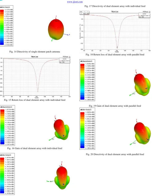
Fig. 5 Dual element array with parallel feed Table 2: Performance of dual element antenna array
Feed Return
Loss Gain Directivity Beamwidth
Individual -19.7dB 10.6dB 10.63dB 400
Parallel -14.5dB 10.2dB 10.2dB 360
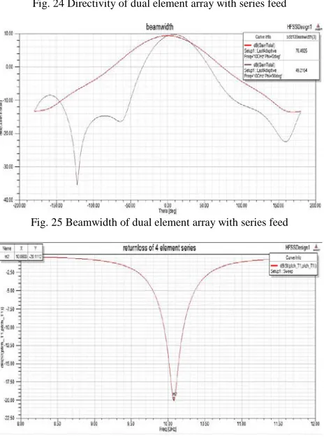
Series -15.5dB 9.62dB 9.7dB 490
6. Design of a Quadruple Element Antenna
Array
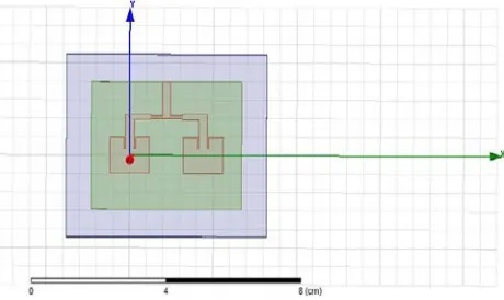
By considerig the same dimensions of the single element and by modifying the postion within the same plane, a quadrapule element antenna array can be deived. Here for the four elements, feed points are required through which the excitation can be provided.[10].
Fig. 6 Quad element array with individual feed
The same dimensions of the single element antenna were used here as well. The separation gap between all the patch elements is one half of its opearting wavelenght i.e, λ/2. Determing the location of the feed point is also important task while designing the antenna [11].
Fig. 7 Quad element array with parallel feed
The same dimensions of the single element patch antenna are also used in design of the 4 element antenna with series
feed. The separation gap between two patches is λ/2. As
the number of elements are increasing the dimensions of the substrate also increases.
Fig. 8 Quad element array with series feed
The performance analysis of a quad element antenna array can be depicted from the following Table 2.
Table 3: Performance of quad element antenna array
Feed Return
Loss Gain Directivity Beamwidth
Individual -20.1fB 13.6dB 13.65dB 200
Parallel -27.5dB 13dB 13.73dB 170
Series -22.7dB 11.9dB 11.95dB 400
7. Design of a Octa Element Antenna Array
www.ijiset.com
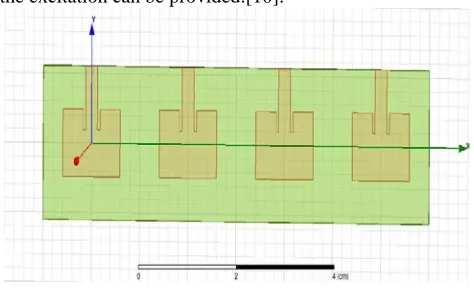
Fig. 9 Octa element array with individual feed
In 8 element antenna array, the feeding network is arranged in a parallel way. T-network is the basic configuration for the design of the feedline. Here 50ohm, 75ohm and 100ohm are the available line impedance and they can be choosen as per requirement.[13].
Fig. 10 Octa element array with parallel feed
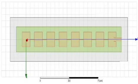
Above the substrate all the 8 elements are placed serially and they are connected with each other thorugh a narrow feedline. The feedpoint is located at the extreme patch and the excitation is given to it and all the remaining elements gets excited because of the narrow feedline with a terminating impedance of 50ohm. The placing between each element is maintained constant all throught the deign λ/2.
Fig. 11 Octa element array with series feed
The performance analysis of a octa element antenna array can be depicted from the following Table 3.
Table 4: Performance of octa element antenna array
Feed Return
Loss Gain Directivity Beamwidth
Individual -20.4dB 16.6dB 16.62dB 110
Parallel -18.8dB 16.5dB 16.5dB 90
Series -28dB 13.2dB 13.3dB 340
8. Results And Discussions
The following section gives the comparison analysis and plots of the respective designs.
Fig. 12 Single element patch antenna
www.ijiset.com
Fig. 14 Directivity of single element patch antenna
Fig. 15 Return loss of dual element array with individual feed
Fig. 16 Gain of dual element array with individual feed
Fig. 17 Directivity of dual element array with individual feed
Fig. 18 Return loss of dual element array with parallel feed
Fig. 19 Gain of dual element array with parallel feed
www.ijiset.com
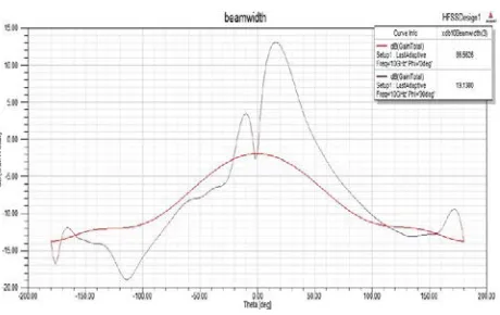
Fig. 21 Beamwidth of dual element array with parallel feed
Fig. 22 Return loss of dual element array with series feed
Fig. 23 Gain of dual element array with series feed
Fig. 24 Directivity of dual element array with series feed
Fig. 25 Beamwidth of dual element array with series feed
Fig. 26 Return loss of quad element array with individual feed
www.ijiset.com
Fig. 28 Directivity of quad element array with individual feed
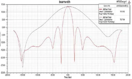
Fig. 29 Beamwidth of quad element array with individual feed
Fig. 30 Return loss of quad element array with parallel feed
Fig. 31 Gain of quad element array with parallel feed
Fig. 32 Directivity of quad element array with parallel feed
www.ijiset.com
Fig. 34 Return loss of quad element array with parallel feed
Fig. 35 Gain of quad element array with series feed
Fig. 36 Directivity of quad element array with series feed
Fig. 37 Beamwidth of quad element array with series feed
Fig. 38 Return loss of octa element array with individual feed
Fig. 39 Gain of octa element array with individual feed
www.ijiset.com
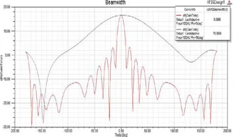
Fig. 41 Beamwidth of octa element array with individual feed
Fig. 42 Return loss of octa element array with parallel feed
Fig. 43 Gain of octa element array with parallel feed
Fig. 44 Directivity of octa element array with parallel feed
Fig. 45 Beamwidth of octa element array with paralle feed
Fig. 46 Return loss of octa element array with series feed
www.ijiset.com
Fig. 48 Directivity of octa element array with series feed
Fig. 49 Beamwidth of octa element array with series feed Table 5: Overall performance analysis of antenna array
Parameter Least
Value Enhanced Value Design of enhanced value
Return loss -18.8dB -28dB 8 element series
Gain 16.6dB 9.62dB individual 8 element
Directivity 16.62dB 9.7dB individual 8 element
Beamwidth 90 490 8 element parallel
The designed array antenna whose central frequency is around 10GHz can be adopted into Radar applications because of its low beam width. Return loss is enhanced when the antenna is feeding in serial, and there is a variation in the value of return loss for parallel feed because of number of elements. Whereas is individual feed, the variation in the return loss also increases but it is negotiable. If the number of conducting elements in an array is increasing then the gain anf directivity are also increasing. Hence it can be concluded that when compared to all three types of feeding methods, individual feed offers better results in terms of Gain and Directivity.
9. Conclusions
The designed array antenna whose central frequency is around 10GHz can be adopted into Radar applications because of its low beam width. Return loss is enhanced when the antenna is feeding in serial, and there is a variation in the value of return loss for parallel feed because of number of elements. Whereas is individual feed, the variation in the return loss also increases but it is negotiable. If the number of conducting elements in an
array is increasing then the gain anf directivity are also increasing. Hence it can be concluded that when compared to all three types of feeding methods, individual feed offers better results in terms of Gain and Directivity.
References
[1] Kraus, John D. "Antennas." (1988).
[2] Raju, G. S. N. Antennas and wave propagation. Pearson Education India, 2006.
[3] Pozar, David M. "Microstrip antenna aperture-coupled to a microstripline." Electronics letters 21 (1985): 49.
[4] Naik, K. Srinivasa, and S. Aruna. "Investigations on the generation of patterns for marine radar applications." Indian Journal of Science and Technology 9, no. 7 (2016).
[5] Naik, K. Srinivasa, and G. S. N. Raju. "Studies on Difference patterns from Cosecant patterns." IOSR-JECE 9, no. 6 (2014): 37-44.
[6] Balanis, Constantine A. Antenna theory: analysis and design. John Wiley & Sons, 2016.
[7] Skolnik, Merrill Ivan. "Radar handbook." (1970).
[8] Marrocco, Gaetano. "The art of UHF RFID antenna design: impedance-matching and size-reduction techniques." IEEE antennas and propagation magazine 50, no. 1 (2008): 66-79. [9] Garg, Ramesh. Microstrip antenna design handbook. Artech
house, 2001.
[10] Carver, Keith, and James Mink. "Microstrip antenna technology." IEEE transactions on antennas and propagation 29, no. 1 (1981): 2-24.
[11] Mak, C. L., K. M. Luk, K. F. Lee, and Y. L. Chow. "Experimental study of a microstrip patch antenna with an L-shaped probe." IEEE Transactions on Antennas and Propagation 48, no. 5 (2000): 777-783
[12] Kumar, Girish, and K. P. Ray. Broadband microstrip antennas. Artech House, 2003.
K.Srinivasa Naik received the Bachelor of Engineering in Electronics
and Communication Engineering in the year of 2005 from Andhra University and the Master of Engineering in Electronic Instrumentation Engineering in 2008 from Andhra University College of Engineering (A). He received his Ph.D degree in the department of Electronics and Communication Engineering, Andhra University College of Engineering (A). Currently he is working as a Associate Professor in Vignan’s Institute of Information Technology, Visakhapatnam. His Research interests include Array Antennas, EMI/EMC and Soft Computing. He is a life member of SEMCE (India). He has 15 International journals under his name. 2 National conferences in proceeding.
K. Srinivasu received the bachelor of Engineering in Electronics and