Modelling And Analysis Of Transformer Tank
Abdul Khaleel& B Kiran Kumar
[1]M.Tech (AMS), Department of Mechanical Engineering, HITAM, Hyderabad, T.S, INDIA [2]Assistant Professor, Department of Mechanical Engineering, HITAM, Hyderabad, T.S, INDIA
Abstract-Transformers are among the most
important blocks in any power generation plant. Enhancing the performance of a particular transformer would positively reflect on the quality of its power transmission. Hence, power plant OEM (original equipment manufacturers) is continuously in pursuit of minimizing losses for reasons of efficiency, energy conservation and environmental factors as well as commercial considerations. The most common reasons of transformer failures are caused by excessive vibrations due to resonance. In this project vibration transfer in the structure shall be characterized.
The tank was modeled by using NX 8.0 and it was imported to ansys 14.0 To find the natural frequency & vibrations of transformer tank one Newton force is applied. In this project two types of analysis are being done. They are Modal analysis and harmonic analysis. In modal analysis displacement is being calculated. Harmonic analysis are carried out to calculate amplitude at different displacements Harmonic analysis is done by taking generated rfrq file from modal analysis. These two analyses are carried out by taking same node points on the walls of the tank for all the models. Comparing the results of all the models it’s being concluded that, the model by adding horizontal stiffeners achieved assumed objective to minimize vibrations to avoid resonance at critical operating frequencies at 50Hz and 100Hz frequency.
I. INTRODUCTION
In this rapid developing world, the use of electricity is in great demand. For transmission and distribution network to transfer large amount of electricity over a long distance with minimum losses and least cost. Transformers enable these changes in voltage to be carried out efficiently. Transformers are among the most important blocks in any power generation plant. Enhancing the
performance of a particular transformer would positively reflect on the quality of its power transmission.
The most common cause of power transformer failures is mechanical defect brought about by excessive vibration, which is formed by the combination of multiples of a frequency of 120 Hz. In this paper, the types of mechanical exciting forces applied to the power transformer were classified, and the mechanical damage mechanism of the power transformer was identified using the vibration transfer route to the machine or structure. The general effects of 120 Hz-vibration on the enclosure, bushing, Buchholz relay, pressure release valve and tap changer of the transformer were also examined.
This project represents the preliminary structural modeling and analysis of transformer tank.The transformer protection is an essential part of overall system protection strategy. Moreover, transformers have a wide variety of features, including tap changers, phase shifters and multiple windings that require special consideration in the protective system design.
Hence, power plant original equipment manufacturers are continuously in pursuit of minimizing losses for reasons of energy conservation and environmental as well as commercial considerations. The most common reasons of transformer failures are mechanical caused by excessive vibrations. In this project the types of mechanical exciting forces applicable to the transformer shall be classified. Vibration transfer in the structure shall be characterized.
II. DESIGN OF TANK
the high temperature in the transformer core and coil, the losses of the core and coil increases. In small capacity transformers the surrounding air will be in a position to cool the transformer effectively and keeps the temperature rise well within the permissible limits. As the capacity of the transformer increases, the losses and the temperature raises. In order to keep the temperature rise within limits, air may have to be blown over the transformer. This is not advisable as the atmospheric air.
Containing moisture, oil particles etc., may affect the insulation. To overcome the problem of atmospheric hazards, the transformer is placed in a steel tank filled with oil. The oil conducts the heat from core and coil to the tank walls. From the tank walls the heat goes dissipated to surrounding atmosphere due to radiation and convection. Further as the capacity of the transformer increases, the increased losses demand a higher dissipating area of the tank or a bigger sized tank. These calls for more space, more volume of oil and increases the cost and transportation problems. To overcome these difficulties, the dissipating area is to be increased by artificial means without increasing the size of the tank. The dissipating area can be increased by
1. Fitting stiffeners to the tank walls. 2. Fitting tubes to the tank
3. Fitting fins to the tank walls 4. Using auxiliary radiator tanks
III. DESCRIPTION OF THE TANK
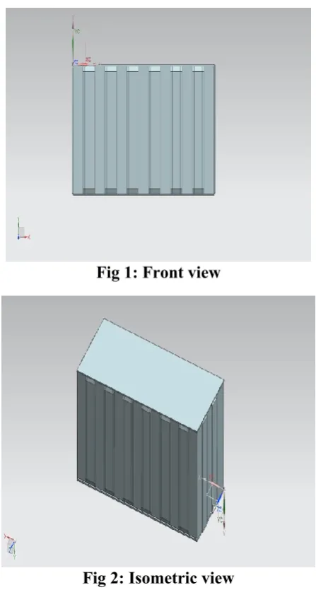
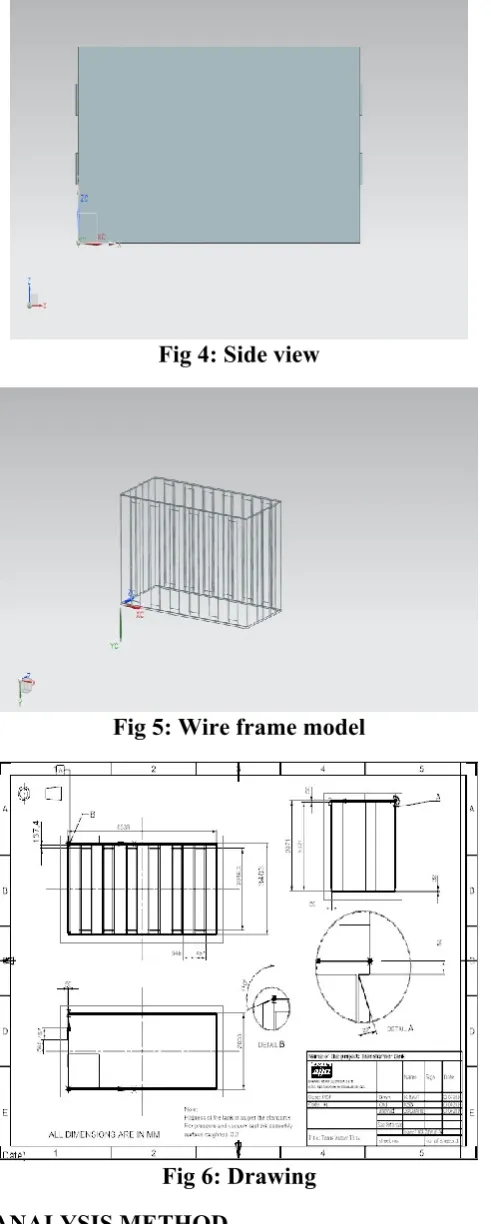
The dimensions of tank depends on the requirements and capacity of transformer, voltage rating and electrical clearance to be provided between the transformer and tank, clearance to accommodate the range, the transformer tank dimension’s are assumed to be
3403mm in respect of tank height 6538mm in respect of tank length and, 2833mm in respect of tank width. Tank wall thickness 8mm/10mm. Bottom plate thickness 50
Top plate thickness 32mm Side stiffeners 8mm
Horizontal stiffeners 16mm
Fig 1: Front view
Fig 2: Isometric view
Fig 4: Side view
Fig 5: Wire frame model
Fig 6: Drawing
ANALYSIS METHOD
Natural frequency: frequency of free vibration of the system. It is a constant for a given system or Elastic vibrations in which there is no friction after
the initial release of the body are known as free or natural vibrations.
The natural frequency is
since ω = 2πf,
and, since T = 1/f where T is the time period,
These equations demonstrate that the simple harmonic motion is isochronous (the period and frequency are independent of the amplitude and the initial phase of the motion).
Resonance: The vibration the system when the frequency of the external force is equal to the natural frequency of the system. The amplitude of vibration at resonance becomes excessive.
IV. RESULTS
In this paper two types of results are carries out. Modal analysis results
Natural frequencies:
***** RESULTS: Modal-1 *****
Time/Freq Load Set Sub step Cumulative
46.849 1 1 1
46.859 1 2 2
48.721 1 3 3
59.011 1 4 4
59.050 1 5 5
59.060 1 6 6
64.595 1 7 7
65.528 1 8 8
65.914 1 9 9
66.140 1 10 10
66.703 1 11 11
67.002 1 12 12
69.564 1 13 13
71.440 1 14 14
71.718 1 15 15
72.889 1 16 16
73.709 1 17 17
74.773 1 19 19
76.091 1 20 20
76.443 1 21 21
78.237 1 22 22
78.715 1 23 23
78.976 1 24 24
82.016 1 25 25
84.277 1 26 26
84.376 1 27 27
85.777 1 28 28
87.252 1 29 29
87.709 1 30 30
88.899 1 31 31
90.128 1 32 32
90.206 1 33 33
92.889 1 34 34
92.916 1 35 35
93.296 1 36 36
96.147 1 37 37
96.616 1 38 38
99.245 1 39 39
99.989 1 40 40
100.84 1 41 41
102.67 1 42 42
103.08 1 43 43
103.10 1 44 44
103.78 1 45 45
105.40 1 46 46
106.13 1 47 47
109.38 1 48 48
109.96 1 49 49
***** RESULTS: Model-2 ***** Set Time/Freq Load Step Sub step Cumulative 46.875 1 1 1
47.606 1 2 2
49.157 1 3 3
59.057 1 4 4
59.477 1 5 5
63.878 1 6 6
65.338 1 7 7
66.982 1 8 8
71.507 1 9 9
73.961 1 10 10
74.095 1 11 11
77.805 1 12 12
79.750 1 13 13
79.929 1 14 14
80.002 1 15 15
81.829 1 16 16
85.442 1 17 17
85.671 1 18 18
90.012 1 19 19
92.805 1 20 20
94.906 1 21 21
96.628 1 22 22
101.86 1 23 23
102.09 1 24 24
102.60 1 25 25
102.86 1 26 26
104.21 1 27 27
104.90 1 28 28
105.52 1 29 29
***** RESULTS: Model-3 ***** Time/Freq Load Step Sub step Cumulative 46.844 1 1 1
47.233 1 2 2
48.453 1 3 3
58.716 1 4 4
59.471 1 5 5
61.767 1 6 6
65.876 1 7 7
67.089 1 8 8
67.278 1 9 9
67.307 1 10 10
68.562 1 11 11
69.284 1 12 12
71.761 1 13 13
72.403 1 14 14
73.538 1 15 15
75.538 1 16 16
75.799 1 17 17
76.563 1 18 18
77.733 1 19 19
79.090 1 20 20
79.490 1 21 21
79.716 1 22 22
82.479 1 23 23
82.891 1 24 24
85.017 1 25 25
86.264 1 26 26
86.890 1 27 27
86.977 1 28 28
89.676 1 29 29
93.053 1 30 30
102.43 1 32 32
102.43 1 33 33
102.60 1 34 34
105.12 1 35 35
105.22 1 36 36
105.69 1 37 37
108.55 1 38 38
108.66 1 39 39
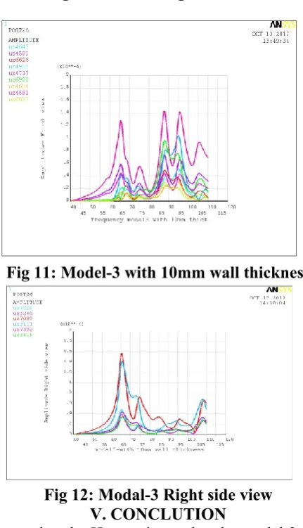
Harmonic Analysis Results
Fig 7: Model-1 without horizontal stiffeners
Fig 8: Model-1 without horizontal stiffeners: right side view
Fig 10: Model-2 right side view
Fig 11: Model-3 with 10mm wall thickness
Fig 12: Modal-3 Right side view V. CONCLUTION
Comparing the Harmonic results, the modal 2 with horizontal stiffeners is achieved low amplitude. Hence Vibrations will be reduced in the structure modal 2 is characterized that the losses in transformer tank, which damp the vibrations and avoids resonance.
REFERENCES
1. Finite element analysis- an introduction to ansys by saeed moaveni, Pearson publications.
2. Mechanical vibrations-by G.K groover.
3. Ansys structural analysis guide by ansys tutorials, ansys incorporation.
Journals
1.0 Structure-vibration Analysis of a Power Transformer
(World Academy of Science, Engineering and Technology)
2.0 Finite Element Analysis of the Stray Loss in Power Transformer Structure Parts.