Two-Element Compact Antennas Decoupled with a Simple
Neutralization Line
Yangsong Ou, Xiaoyang Cai, and Kewei Qian*
Abstract—A simple and novel WLAN antenna and a kind of neutralization line, which introduces a certain amount of signal to cancel out the unwanted mutual coupling between two antennas, are designed in this paper. The WLAN antenna working at 2.45 GHz and 5.8 GHz frequency bands is designed, fabricated and measured. The simulated and measured results show that the isolation between the two decoupled antennas can be improved to above 20 dB in both frequencies after decoupling. The lumped match network occupies less space for antennas and gains a good matching performance in the operating frequencies.
1. INTRODUCTION
The increasing demands for higher data transmission rate and better transmission quality lead to a corresponding demand for MIMO technology, which can increase the transmission speed and communication capacity of the system without increasing the transmission power and design costs. If MIMO antennas are arranged in a size-constraint terminal, there will be strong mutual couplings between array ports. In this situation, the mutual couplings not only deteriorate the radiation efficiency but also increase the correlation coefficient. It is a great challenge to achieve good isolation, while the antenna element spacing is less than half-wavelength in a compact volume [1]. To solve this problem, several decoupling methods, such as defected ground structures [2], electromagnetic band gap [3], coupled resonator decoupling network [4–7], and lumped network [8], are used to improve isolation between closely packed antennas.
In this paper, a simple decoupling network consisting of a neutralization line is placed between two coupled dual-band antennas. It can effectively improve isolation in both the 2.45 GHz and 5.8 GHz frequency bands. Meanwhile, a C-shaped radiating patch is designed in order to miniaturize the antenna size.
Figure 1. Circuit model of two dual-band antennas with lossless network.
Received 18 November 2016, Accepted 18 December 2016, Scheduled 10 January 2017 * Corresponding author: Kewei Qian ([email protected]).
bands. The corresponding admittances [Y11A], [Y22A] are purely real numbers and should be equal toY0. The admittance matrix [YD] of the lossless network must be purely imaginary numbers. On the other hand, the mutual admittance [Y21A] of the coupled dual-band antennas is a complex number. To meet the demand of good port isolation, the off-diagonal elements of admittance matrix Y should be zero. Consequently, a phase-shifting network is used to convert the mutual admittance [Y21A] into a purely imaginary number. The dual-band decoupling conditions can be simplified as shown in Eq. (2) [3]
Re[Y21A(ω)] ≈ 0 (2a)
Im[Y21A(ω)] + Im[Y21D(ω)] ≈ 0 (2b) ω is the center angular frequency of two frequency bands (2.4 GHz–2.484 GHz) and (5.725 GHz– 5.85 GHz). To satisfy the condition in Eq. (2a), a two-section stepped-impedance transformer is used as a phase-shifting network to convert the mutual admittance of the coupled antennas into a purely imaginary number, while keeping the impedance still match. It should be pointed out that the key technique is the design of the lossless decoupling network, which can satisfy the condition in Eq. (2b). However, the decoupling network will cause mismatching. To solve the problem, extra matching networks are added to the antenna after decoupling.
3. DESIGN PROCESS
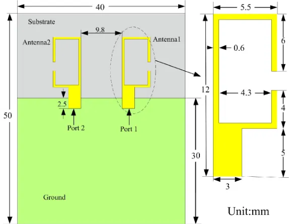
Based on the above theories, two symmetrical antennas are printed on an FR4 substrate with a relative permittivity of 4.4 and size of 50 mm×40 mm×1.6 mm. The antennas have a space of 9.8 mm and operate at 2.45 GHz and 5.8 GHz frequency bands, as shown in Fig. 2. The corresponding simulated
Figure 3. SimulatedS-parameters of the proposed antenna.
(a) (b)
Figure 4. Simulated mutual admittance parameters of the coupled antennas with the phase shifting; and simulated mutual admittance parameters of the lossless network at (a) the low band; and (b) the high band.
S-parameters are shown in Fig. 3. From the simulated results, it is indicated that the isolations between the two antennas are around 5.5 dB at 2.45 GHz and 11.4 dB at 5.8 GHz, and the return losses are about 16.5 dB at 2.45 GHz and 18 dB at 5.8 GHz.
For a single-band antenna, the detailed explanation of a phase shifting can be found in [4]. However, in this paper, a two-section stepped-impedance transformerAis proposed as a phase shifter in the dual-band antenna. As shown in Figs. 4(a) and (b), the absolute values of Re[Y21A] are below 0.0025 S at the lower band and below 0.002 S at the higher band. The imaginary part of the mutual admittance of the coupled dual-band antennas needs to be constant within the band of interest.
It can be seen from Figs. 4(a) and (b), the imaginary part Im[Y21A] of the mutual admittance of the antenna with the phase shifting is −0.0125 S at 2.45 GHz and −0.0075 S at 5.8 GHz. The neutralization line is inserted to the dual-band antennas in parallel. By adjusting the length and width of the neutralization line, it can produce an opposite coupling towards the load antenna. When the length is 6.4 mm and width 0.3 mm, the imaginary part Im[YD
21] of the neutralization line is opposite to the antenna’s imaginary part Im[YA
21] in both low and high bands, as depicted in Figs. 4(a) and (b). Since the decoupling network will cause mismatching, an LC matching network is added to each port to match the decoupled antennas. Therefore, the LC value can be turned using the Method of Moments solver in Agilent’s ADS to satisfy the impedance matching. Fig. 5 shows the layout of the decoupled antennas, and a muRata capacitance C1 = 2.5 pF and coilcraft inductance L1 = 9.1 nH are used. The simulated results are obtained by HFSS version 15.0, and the measured results are performed by an Agilent E8363B vector network analyzer, as shown in Fig. 6. In this figure, it is apparent that the isolations between the decoupled antennas are more than 20 dB, and the return losses are better than 15 dB in both 2.4∼2.484 GHz and 5.725 GHz∼5.85 GHz bands.
Figure 5. Layout of the decoupled MIMO antenna.
Figure 6. Simulated and measuredS-parameters of the decoupled antenna.
(a) (b)
Figure 7. Simulated surface current distributions at (a) 2.45 GHz, and (b) 5.8 GHz.
(a) (b)
Figure 8. (a) Top pattern of the fabricated antenna. (b) Bottom pattern of the fabricated antenna.
(a) (b)
Figure 9. Measured radiation patterns for the decoupled antenna inXOZ (H) plane,Y OZ (E) plane at (a) port 1, and (b) port 2.
70 72 74 76 78 80 82 84 86 88 90
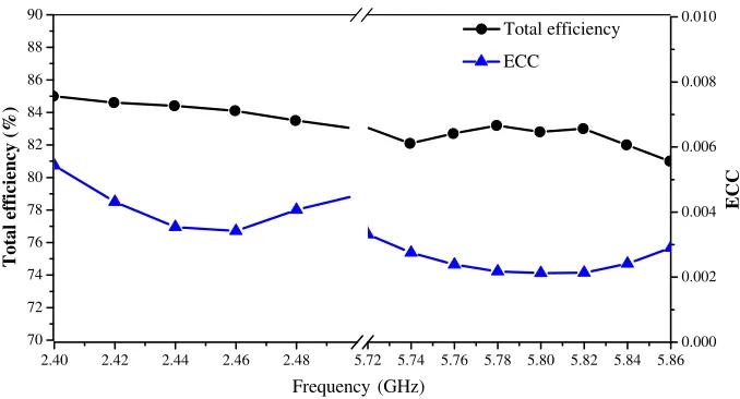
2.40 2.42 2.44 2.46 2.48 5.72 5.74 5.76 5.78 5.80 5.82 5.84 5.86 0.000 0.002 0.004 0.006 0.008 0.010 To ta l ef fi ciency (% ) Total efficiency ECC Frequency (GHz) ECC
Figure 10. Simulated total efficiency and calculated ECC.
Electronics Letters, Vol. 44, No. 25, 1441–1442, 2008.
2. Ding, Y., Z. Du, K. Gong, and Z. Feng, “A novel dual-band printed diversity antenna for mobile terminals,” IEEE Transactions on Antennas and Propagation, Vol. 55, No. 7, 2088–2096, 2007. 3. Luberto, M. and W. S. Fano, “Microstrip antenna design using EBG (electromagnetic band gap)
structures at 2.4 GHz,” 2015 XVI Workshop on Information Processing and Control., 1–7, 2015. 4. Qian, K. W., L. Y. Zhao, and K. L. Wu, “An LTCC coupled resonator decoupling network for two
antennas,”IEEE Transactions on Microwave Theory and Techniques, Vol. 63, No. 10, 3199–3207, 2015.
5. Zhao, L. Y. and K. L. Wu, “A coupled resonator decoupling network for in-device coexistence of two collocated antennas,”2014 Asia-Pacific Microwave Conference, 867–869, 2014.
6. Zhao, L. Y., K. W. Qian, and K. L. Wu, “A cascaded coupled resonator decoupling network for mitigating interference between two radios in adjacent frequency bands,” IEEE Transactions on Microwave Theory and Techniques, Vol. 62, No. 11, 2680–2688, 2014.
7. Zhao, L. Y. and K. L. Wu, “A dual-band coupled resonator decoupling network for two coupled antennas,”IEEE Transactions on Antennas and Propagation, Vol. 63, No. 7, 2843–2850, 2015. 8. Wu, C. H., C. L. Chiu, and T. G. Ma, “Very compact fully lumped decoupling network for a coupled
two-element array,”IEEE Antennas and Wireless Propagation Letters, Vol. 15, 158–161, 2016. 9. Diallo, A., C. Luxey, P. L. Thuc, R. Staraj, and G. Kossiavas, “Study and reduction of the mutual