The Electromagnetic Properties of the Generalized Cantor Stack
in Spherical Multilayered Systems
Gennadiy Burlak1, *, M. N´ajera-Villeda1, and Ren´e Santaolaya-Salgado2
Abstract—By the transfer matrix approach we numerically study the electromagnetic properties (narrow peak positions) of the transmission spectra for microspheres coated by a multilayered stack with the generalized Cantor structure (fractal). As opposed to the standard Cantor system with removedγ/3 [γ = 1] section we consider here the solid stack with Si/SiO2 layers at general γ value. In such a solid
composition the SiO2 layers replace the empty Cantor sections and the parameter γ acquires meaning
of a specific control parameter. At successive generations the central layers (in blocks of the spherical stack) acquire a progressive decreased width that leads to generation of the radially inhomogeneous defects. We show that the wave phase interference in such a fractal pattern leads to formation of very narrow electromagnetic transmittance resonances that can be used in modern optoelectronics.
1. INTRODUCTION
It is well known that except for the whispering gallery mode (WGM) regime [1, 2], a bare dielectric sphere has a complex spectrum electromagnetic low quality (Q factor) eigenoscillations because of the energy leakage into the outer space [3]. The case of the compound structure, when the dielectric sphere is coated by an alternative stack, is much richer. The Q-factor of optical oscillations has a large value in the frequency regions of weak transmission, and beyond these regions, Q remains small [4–13]. In this paper we numerically analyze the wave phase interference in a Cantor generalized fractal pattern in the spherical stack. To do that we explore the transmission spectra and frequency resonances of such structures deposited on surface of a dielectric microsphere.
2. THE GENERALIZED CANTOR SET
The well known Cantor set is created by repeatedly deleting the open central third of a set of line segments. One can construct various generalizations of the set by, say, cutting the segments into a different number of intervals or choosing another scaling factor (see, e.g., [14, 15]. In this paper, we construct a Cantor stack by repeatedly replacing (not deleting) of the central third of a set of stack by layer of material. The generalized Cantor set in radial direction can be constructed from a homogeneous stack by following iterations.
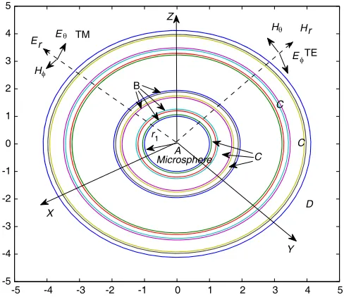
The zero-order iteration (initiator) is the homogeneous spherical stack deposed on the surface of the bare microsphere A (see Fig. 1) with radius r1. A layer of the stack has width d, which is
separated (as 2B +C) in two symmetric periphery fragments (B) with length pd and one central fragment (C) with length γpd respectively (γ is a free parameter), such that for 2B +C system the length is pd+γpd+pd=d. From the latter we obtain p= 1/(2 +γ). Ifγ = 1 such case is simplified to the standard Cantor set. In this paper, we apply such idea as follows. We generate in 1-st iteration (1st
Received 10 June 2014, Accepted 13 July 2014, Scheduled 7 August 2014 * Corresponding author: Gennadiy Burlak ([email protected]).
1 Centro de Investigaci´on en Ingenier´ıa y Ciencias Aplicadas, Universidad Aut´onoma del Estado de Morelos, Cuernavaca, Mor.,
-5 -4 -3 -2 -1 0 1 2 3 4 5 -5
-4 -3 -2 -1 0 1 2 3 4 5
E
H
Microsphere
Y Z
C C Er
Hr H
E TE
B
A
X
C
D TM
r1
θ
φ
φ θ
Figure 1. The structure of the multilayered microsphere coated by a Cantor stack with order R3 (15
layers). A is a bottom glass microsphere (n= 1.5) with radius r1, B is Si layer (n= 3.58), C is SiO2
(n= 1.46) layer, D is surrounding space. Typically r1 ∼1µm, the width of layers dependently on the
position in a Cantor stack isd∼(1.3÷0.06)µm.
with order R1) the stack as B1+C1+B1 (3 layers in the stack,R1 order). In 2-nd iteration we have
(B2+C2+B2) +C1+ (B2+C2+B2) (7 layers in the stack, R2 order). Applying the same approach
one can see that the stack R3 consists of 15 alternating layers. In general the rule to construct of the
fragments B, C of stack can be written as
Bi →Bi+1+Ci+1+Bi+1, Ci →Ci+1. (1)
In standard Cantor set the central fragmentC is removed in the iterations that leads to a Cantor “dust” fractal [14]. However in this paper we replace C (rather than delete) fragment by SiO2 layer,
while B fragment is replaced by Si layer. This allows constructing a solid spherical quasiperiodic stack with the generic properties of a Cantor fractal pattern. For such fractal the dimensionless scaling factor γ becomes a control parameter that takes values between 0 and 2. Although such Cantor stack has the alternating structure BC, . . . , CB, . . ., but due to no-symmetric generation rule (1) it is not longer periodic composition rather than a sequence of nonperiodic defects. Such stack looks like a pattern with progressive decreasing spatial scales (see Fig. 1) that leads to formation of extremely narrow transmittance resonances in the frequency domain due to the field phase interferences in such a structure.
3. BASIC EQUATIONS
To study the spectra of such system we solve the Maxwell equations for fields E, B and the dielectric permittivity εof a layer. The Maxwell equations in the spherical coordinate frame (ρ, θ, ϕ) usually is reduced to the Helmholz equation for a Debye potential Π(ρ, θ, ϕ) [17]. To avoid needless repetitions, the case of TM waves is investigated here with details, the case of TE waves can be studied by similar way. The solution for E and H fields in terms of the Debye potential Π(ρ, θ, ϕ) is given by
Eθ= krε1 ∂
2Π(ρ, θ, ϕ)
∂r∂θ , Hϕ = i r
∂Π(ρ, θ, ϕ)
∂θ
0
μ0.
(2)
In every layer of the stack, one uses the next matrix presentation for the fields: (see e.g., Ref. [16] and references therein)
u=
Hφ Eθ
=D·
a b
whereaand b are arbitrary constants and matrixD =D(y) is given by (see more details in Ref. [16]):
D=
inPm(2)(y)eiy inPm(1)(y)e−iy G(2)m (y)eiy G(1)m (y)e−iy
, q=
a b
,
Here n is the refractive index of a particular layer, Pm(1,2)(y) the rational part of Hankel spherical functionsh(1m,2)(y) =Pm(1,2)(y)e±iy,G(1m,2)(y) the rational part of a derivative of Hankel spherical functions
(∂/∂y)h(1m,2)(y) = Gm(1,2)(y)e±iy, and m the number of a spherical harmonic, y = ωnr/c. This allows presentation of the reflection coefficientR=R(ω) and transmission coefficientT =T(ω) in the following form (σ = (n0/nN)1/2) [16]
R=R(ω) = Q21(ω)
Q11(ω), T
=T(ω) = 1
σQ11(ω).
(4)
where matrix Qij(ω) depends on Pm, Gm and is written in [16]. In (4) two equations relate three
variables: R, T and frequencyω. Definingω, one can calculate the frequency dependence ofR(ω),T(ω) for the spherical stack. It is worth to note that both the reflection coefficient R and the transmittance coefficientT depend also on the number of a spherical harmonicm. Below we give more attention to the dynamics of the transmittance coefficient T. The eigenfrequencies equation for a coated microsphere follows from the boundedness of fields in the microsphere center and it has a simple formR(ω) = 1 [16].
4. NUMERICS
Our results are shown in Figs. 2–5. As it was already mentioned such a Cantor set has the alternating structure ABCB, . . . , CB, . . . , D that due to non-symmetric rule Eq. (1) generates the sequence of (nonperiodic) defects. Such a stack with diminishing spatial scales can form very narrow electromagnetic transmittance resonances due to quasiperiodic phase interplay of photons. Due to radial dependence of the electromagnetic fields (in general we have to use Hankel functions rather than sine and cosine) it is very difficult to analyze the frequency spectrum of such Cantor stack analytically. Therefore in what follows the numerical methods will be used.
200 400 600
0.4 0.6 0.8
T
(a)
200 400 600
0.2 0.4 0.6 0.8
(b)
200 400 600
0.2 0.4 0.6 0.8
f [THz]
T
(c)
200 400 600
0.2 0.4 0.6 0.8
f [THz]
(d)
Figure 2. Transmittance spectra for the spherical Cantor stack with different orderRlfor the frequency
First we consider the structure of the frequency spectrum of the transmittance at change of the number of layers (order Cantor subset Rl) of the stack. The case m= 1 is studied with more details.
We consider that on each step l a Cantor sequence is created by splitting Si layer into three fragments from which the central one is replaced by SiO2 material. In the first case the system consists of three
layers (that isR1 order), in the second case the system consists of 7 layers (orderR2). In the third and
fourth cases the system consists of 15 and 31 layers respectively (R3 and R4 orders). Further we study
the practically important interval of frequencyf =ω/2π from 100 [THz] to 600 [THz].
Figure 2 shows the structure of the frequency spectrum for differentRl for the simplest caseγ = 1
(standard Cantor configuration). Fig. 2(a) shows that for R1 order (three layers in the stack) the
spectrum has a simple periodic structure. However already for R2 stack the spectrum becomes more
complicate (see Fig. 2(b)) and narrow resonances of high transmittance are generated. Further the order increasing to R3 (Fig. 2(c)) leads to the extremely narrower resonances. Then for R4 stack, as
Fig. 2(d) shows, the spectrum acquires the irregular shape.
It is instructive to explore the general case of the control parameter γ to see how the value of γ
affects the structure of the transmittance spectrum in the considered Cantor multilayered microsphere. Such dependencies of transmittance T as a function of γ forR3 stack are displayed in Fig. 3 for γ <1
and in Fig. 4 for 1< γ <2. One can see from Fig. 3 that the narrow resonances are formed by splitting the edges of the transmittance wide zones already at γ = 0.5. From Fig. 3 we also observe that the periodicity in the spectrum practically disappears already for γ= 0.2.
Figure 4 shows that the behavior of the transmittance spectra for case γ >1 differs significantly from caseγ <1 for the same frequency range displayed in Fig. 3. From Fig. 4, we observe a significant shrinking of the high transmittance area in low frequency range.
0
0.2
0.4
0.6
0.8
1
100 150 200 250
300 350 400 450
500 550 600 0
0.5 1
f [THz]
T
γ
Figure 3. Transmittance spectra for the frequency range f from 100 to 600 [THz] for different width parameter γ < 1 from 0.1 up to 0.9 for SiO2layer for spherical stack with a Cantor
structure.
1.1
1.2
1.3
1.4
1.5
1.6
1.7
1.8
1.9
2
100 150 200 250
300 350 400 450
500 550 600 0
0.5 1
f [THz]
T
γ
Figure 4. The same as in Fig. 3 but for 1< γ <
2.
Besides, from Fig. 4 one can observe the appearance of a self-similarity in some parts of the spectra. However, such an effect in spherical structure is not clearly seen due to the frequency dispersion in spherical systems [3]. Mathematically it is expressed by the replacement of the trigonometric functions (plane geometry) by the complex Hankel functions (spherical geometry).
0.5 1 1.5 2 2.5 3 3.5 0.5
1 1.5 2 2.5
(a)
E H n
1 2 3 4
5 10 15 20 25
(b)
0.5 1 1.5 2 2.5
1 2 3 4 5 6 7 8
r/r1
(c)
0.5 1 1.5 2 2.5 3
2 4 6 8 10 12 14
r/r1
(d)
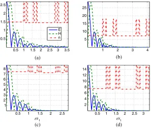
Figure 5. The radial field distribution corresponding to eigenfrequency resonances closely to peaks from Fig. 3. It is shown the cases: (a)γ = 0.8 atf = 300 [THz], (b)γ = 1 atf = 304 [THz], (c)γ = 0.5 at f = 309 [THz], and (d) γ = 0.7 at f = 399 [THz].
along the radius of spherical stack it is shown in Fig. 5 for the spherical number m = 1 (fundamental TM mode). In order to see more details of the fields in a Cantor stack it is also displayed the structure of the refraction index (arbitrary units) of layers. From Fig. 5, we observe that the fields are mainly concentrated in the microsphere, sharply (exponentially) decays in the area of the stack and practically does not leak into surrounding space. One can say that such Cantor spherical structure resonantly confines the field and practically does not allow it to be radiated from the coated microsphere. This can lead to very high values of theQ-factor for such excitations.
5. CONCLUSIONS
In this paper, we have numerically studied the electromagnetic properties (narrow peak positions) of the transmission spectra for microspheres coated by a multilayered stack with the generalized Cantor structure. As opposed to the standard Cantor system with removed γ/3 [γ = 1] section the generalized solid stack with alternating Si/SiO2 layers (in place of empty Cantor section) for such fractal pattern
with general values of γ it is considered. It is found that the variations of γ significantly affects the structure of the spectra. The waves phase interference in such a fractal pattern leads to creation of extremely narrow frequency peaks assisted by the progressively decreased radially inhomogeneous defects. Such peaks can be used in modern optoelectronics, e.g., for construction narrow optical filters.
ACKNOWLEDGMENT
This work was partially supported by CONACyT (Mexico) grants No. 169496 and No. 168104.
REFERENCES
2. Astratov, V., “Fundamentals and applications of microsphere resonator circuits in photonic microresonator research and applications,” Springer Series in Optical Sciences, Vol. 156/2010, 423–457, 2010.
3. Stratton, A., Electromagnetic Theory, McGraw-Hill, New York, 1941.
4. Brady, D., G. Papen, and J. E. Sipe, “Spherical distributed dielectric resonators,”J. Opt. Soc. Am. B, Vol. 10, 644–651, 1993.
5. Burlak, G., S. Koshevaya, J. Sanchez-Mondragon, et al., “Electromagnetic oscillations in the multilayer spherical resonator,”Opt. Commun., Vol. 180, 49–60, 2000.
6. Chan, C. T., W. Y. Zhang, Z. L. Wang, et al., “Photonic band gaps from metallo-dielectric spheres,”Physica B, Vol. 279, 150–159, 2000.
7. Miyazaki, H., H. Miyazaki, K. Ohtaka, et al., “Photonic band in two-dimensional lattices of micrometer-sized spheres mechanically arranged under a scanning electron microscope,” J. Appl. Phys., Vol. 87, 7152–7159, 2000.
8. Talebi R., K. Abbasian, and A. Rostami, “Analytical modeling of quality factor for shell type microsphere resonators,”Progress In Electromagnetics Research B, Vol. 30, 293–311, 2011.
9. Astratov, V. N., A. Darafsheh, M. D. Kerr, K. W. Allen, and N. M. Fried, “Focusing microprobes based on integrated chains of microspheres,” PIERS Online, Vol. 6, No. 8, 793–799, 2010.
10. Astratov, V. N., S. P. Ashili, and A. M. Kapitonov, “Optical properties of mesoscopic systems of coupled microspheres,”PIERS Online, Vol. 3, 2007–278, 2007.
11. Burlak, G., “Enhanced optical fields in a multilayered microsphere with quasiperiodic spherical stack,” Phys. Scr., Vol. 76, 571–576, 2007.
12. Burlak, G. and A. D´ıaz-de-Anda, “Optical fields in a multilayered microsphere with quasiperiodic spherical stack,” Optics. Commun., Vol. 281, 181–189, 2008.
13. Burlak, G., A. D´ıaz-de-Anda, and A. Zamudio-Lara, “The narrow transmission peaks and field confinement produced by defects in a multilayered microsphere,”Optics Commun., Vol. 285, 1542– 1549, 2012.
14. Gouyet, J. F.,Physics and Fractal Structures, Springer, Berlin, 1996.
15. Zhong, Y. X. and Z. H. Wang, “Super narrow bandpass filter using fractal cantor structures,”Int. J. Infrared. Milli., Vol. 25, 1315–1323, 2004.
16. Burlak, G., The Classical and Quantum Dynamics of the Multispherical Nanostructures, Imperial College Press, 2004.
![Figure 2. Transmittance spectra for the spherical Cantor stack with different orderrange(d) Rl for the frequency f from 100 [THz] to 600 for γ = 1](https://thumb-us.123doks.com/thumbv2/123dok_us/7745788.1269156/3.612.176.447.460.685/figure-transmittance-spectra-spherical-cantor-dierent-orderrange-frequency.webp)