DOI: http://dx.doi.org/10.26483/ijarcs.v8i8.4626
Volume 8, No. 8, September-October 2017
International Journal of Advanced Research in Computer Science
RESEARCH PAPER
Available Online at www.ijarcs.info
ISSN No. 0976-5697
AN ANALYSIS OF 10 GBITS/S OPTICAL TRANSMISSION SYSTEM USING
FIBER BRAGG GRATING (FBG) AND DOUBLE EDFA
Ramchandra Mishra
Dept. of Electronics and Communication Jagannath University
Jaipur, Rajasthan
Ramesh Bharti
Dept. of Electronics and Communication Jagannath University
Jaipur, Rajasthan
Abstract: This work is about design & development of an optical transmission system in optical fibre. The optical fibre is always used in telecommunication system because of its characteristics which include small size or dimension, low loss and low interferences from outside environment. There are various types of optical fibre, the Fibre Bragg Grating (FBG) is commonly chosen as important components to compensate the dispersion in optical communication system. FBG is very simple, has low cost filter for wavelength selection and low insertion loss, it has also customized reflection spectrum and wide bandwidth. Our work describes the use of pre & post FBG EDFA (Erbium doped fibre amplifier.) to achieve high power through put at receiver side. The proposed optical communication system is simulated on opitsystem optisim simulator. By simulating the proposed mode of communication system & using the most appropriate settings of the system, which settings of the system which include input power (dBm), fibre cable length (km) and attenuation coefficient (dB/km) at optical cable , different parameters will be investigated which include output power (Watt), noise figure (dB), and gain (dB) at receiver. However the frequency at transmitter (GHz) and cut-off frequency (Bit rate Hz) at receiver will be fixed as initial setting for the simulation.
.
Keyword: Optical Transmission System, Fibre Bragg Grating (FBG), Erbium Doped Fibre Amplifier, Optisystem.
I. INTRODUCTION
Optical fiber
The latest movement which transmits data and organized transmitting messages module onto light waves. With uses glass (or plastic) strings (fibers) to transmit. A fiber optic affiliation contains a store of glass strings, each of which is set up for transmitting messages change onto light waves. The latest movement which transmits data and orchestrated transmitting messages module onto light waves. With uses glass (or plastic) strings (fibers)to transmit. A fiber optic affiliation contains a store of glass strings, each of which is set up for transmitting messages change onto light waves. [1]
Wavelength Division Multiplexing
In fiber optic correspondence structure, wavelength-division multiplexing (WDM) is a movement which multiplexes various optical transporter signals onto a singular optical fiber by using masterminded wavelength (i.e. tones) of laser light. This strategy enables bidirectional trades more than one strand of fiber, and what's more duplication of generally outrageous. A WDM structure uses a multiplexer at the transmitter to join the signs, and a demultiplexer at the beneficiary to part them separated. With the right kind of fiber it is possible to have a contraption that do both meanwhile and can fill in as an optical unite drop multiplexer. This is dependably done by utilization of optical-to-electrical-to-optical (O/E/O) translation at the very edge of the vehicle manage, along these lines permitting spread operation with existing rigging with optical interfaces.
Disseminating compensation Fiber (DCF)
Electronic alter frameworks are utilized as a bit of system. Since there is fast affirmation at the gatherer, arrange twisting’s in the optical space, e.g. chromatic scattering, are
changed over into non straight mutilation after optical - to-electrical change. It is an immediate consequence of reason that the likelihood of nonlinear channel displaying finished. For this generally strengthen forward equalizer (FFF) and choice input equalizers (DFE) structures are utilized. EDC appears down the speed of correspondence since it backs off the computerized to straightforward discourse.
Fiber Bragg Grating (FBG)
Optical fiber Bragg beating (FBG) has beginning late found calm disapproved of utilization in remuneration of scrambling broadening in long-houl correspondence? In this, Chirped fiber pounding (CFG) is favored. CFG is a little all-fiber torpid contraption with low extension episode that is faultless with the transmission structure and CFG's scattering can be effectively balanced. CFG ought to be masterminded in-line for optical outcomes. This is the favored methodology on account of its motivations of excitement including little impression. Low extension hardship diffusing slant remuneration and irrelevant non-straight impacts. Regardless, the arrangement utilizing FBG is mind boggling Misinterpretation. [2, 3]
What is EDFA?
Erbium-doped fiber enhancer (EDFA) is an optical repeater gadget that is used to help the vitality of optical signs being helped through a fiber optic trades framework. An optical fiber is doped with the exceptional earth section erbium so the glass fiber can adjust light at one rehash and radiate light at another rehash.
Working Principles of EDFA
© 2015-19, IJARCS All Rights Reserved 350 or 1480 nm), it is moved to a long-lifetime halfway state, by
[image:2.595.39.278.190.290.2]then it rots back to the ground state by oozing light inside the 1525-1565 nm band. The Erbium can be either pumped by 980 nm light, in which case it encounters a shaky short lifetime state before quickly ruining to a semi stable state, or by 1480 nm light in which case it is especially on edge to the semi stable state. Once in the semi stable state, it rots to the ground state by conveying light in the 1525-1565 nm bands. This rot strategy can be vivified by before light, along these lines acknowledging redesign. The working benchmarks of EDFA are appeared in the Figure.
Figure 1: The working standards of EDFA
Basic Design of EDFA
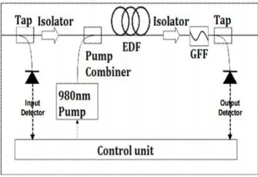
EDFA design is mostly made out of an EDF, a pump laser, and a segment (frequently alluded to as a WDM) for consolidating the flag and pump wavelength so they can proliferate all the while through the EDF. On a basic level, EDFAs can be composed to such an extent that pump vitality engenders an indistinguishable way from the flag (forward pumping), the other way to the flag (in reverse pumping), or both heading together. The pump vitality may either be 980 nm pump vitality, 1480 nm pump vitality, or a blend of both. For all intents and purposes, the most widely recognized EDFA setup is the forward pumping design utilizing 980 nm draw vitality, as appeared in the Figure 2. [4,5,6,7]
Figure 2: The EDFA setup with 980 nm pump vitality
II. LITURATURE REVIEW
An Analysis of 10 Gbits/s Optical Transmission System using Fiber Bragg Grating (FBG)
This paper talked about on a recreation of optical transmission framework in optical fiber. The optical fiber is constantly utilized as a part of media transmission framework due to its qualities which incorporate little size or measurement, low misfortune and low obstructions from outside condition. There are different sorts of optical fiber, the Fiber Bragg Grating (FBG) is ordinarily picked as vital segments to repay the scattering in optical correspondence framework. FBG is extremely basic, has minimal effort channel for wavelength determination and low inclusion misfortune, it has likewise altered reflection range and wide data transfer capacity. The recreation of transmission framework will be broke down in view of various parameters by utilizing OptiSystem test system. By reenacting a model of correspondence framework and utilizing the most appropriate settings of the framework which incorporate info control (dBm), fiber link length (km) and constriction coefficient (dB/km) at link segment, there are three distinct parameters will be examined which are yield control (Watt), commotion figure (dB), and pick up (dB) at beneficiary. Then again, the recurrence at transmitter (GHz) and cut-off recurrence (Bit rate Hz) at beneficiary will be settled before as starting setting for the reenactment.
From the outline and reenactment of optical transmission framework, the diaries related about optical transmission framework have been found and concentrated keeping in mind the end goal to propose the plan thought for a reproduction of optical transmission framework. The optical transmission framework has basic segments like other correspondence framework which comprises of data source (input), transmitter, transmission channel (fiber optic), recipient and the goal (yield). The framework will transmit data utilizing optical bearer wave from transmitter to collector by means of optical fiber. In view of the examination, the transmission framework square graph (Figure 3) has been composed which comprises of laser light as the source, modulator, single mode optical fiber as the channel, fiber Bragg grinding (FBG) as the scattering compensator, optical speaker and the photograph identifier as the light indicator. At that point, the optical transmission framework has been demonstrated by utilizing OptiSystem test system as appeared in Figure 4 keeping in mind the end goal to explore distinctive parameters of the system. From the recreation result, it can infer that the optical fiber length and the lessening coefficient are straightforwardly relative to the clamor figure. The clamor figure is a measure of how much commotion the enhancer adds to the flag. While the pickup is getting lower with the expanding length. Then again, the yield control is diminished in spite of the fact that the info control is expanded because of the use of EDFA and the pickup has been packed. It is on account of the power wellspring of the speaker, the quantity of energized erbium iotas or the quantity of accessible electron-opening sets, are depleted.[8 ]
Investigation on Dispersion Compensation with DCF in view of Optisystem
[image:2.595.38.294.505.680.2]© 2015-19, IJARCS All Rights Reserved 351 reproduction results, for example, Q factor and BER are given
and profoundly investigated. It is discovered that blend pay execution is the best. Furthermore, the info fiber control is taken as 9-10dB, the relating BER execution is better.[9]
Scattering Compensation and Power Optimization utilizing FBG-EDFA in Optical Communication System
Scattering Compensation (DC) and Power Optimization (PO) are very required parameters in Optical Communication System (CS).The proposed correspondence demonstrate indicates Dispersion Compensation utilizing Fiber Bragg Grating (FBG) with Erbium Doped Fiber Amplifier (EDFA).Other than Dispersion Compensation we upgraded practically same power at the recipient end. Scattering and power is obviously envisioned at different focuses particularly at input side (after the Mech-Zehnder modulator), after the 20 km optical fiber and at the recipient end (After the EDFA). Scattering misfortune is effectively remunerated very nearly
85% and influence yield is same 46 μWatt as input. FBG is set at 193.1 THz recurrence (close to 1550 nm Bragg Wavelength). At input side the bit succession generator, Gaussian heartbeat generator and Mech-Zehnder modulator (MZM) is utilized. The power is measured by Optical power Meter (OPM) and Dispersion is imagined by optical time area visualizer (OTDV).[10 ]
Scattering is a noteworthy result of the physical properties of the transmission medium. Single-mode filaments, utilized as a part of fast optical systems, are liable to Chromatic Dispersion (CD) that causes beat widening relying upon wavelength, and to Polarization Mode Dispersion (PMD) that causes beat expanding relying upon polarization. Unreasonable spreading of light heartbeat will make bits "flood" their expected availabilities and cover nearby bits. At the beneficiary side it might experience issues to decipher contiguous bits, expanding the Bit Error Rate.[11]
Examination on Scattering Pay Utilizing Post FBG with EDFA
We consider that WDM Optical correspondence organizes offers high potential transfer speed and adaptability regarding high piece rate transmission. Be that as it may, their execution backs off because of some parameter like scattering, lessening, dissipating and unsynchronized piece design. In whole deal application, scattering is the primary parameter which should be repaid with a specific end goal to give abnormal state of unwavering quality of administration. Fiber Braggs Grating (FBG) is a standout amongst the most generally utilized component to remunerate it. In this article, the recreation model of the WDM in light of the Optisystem is exhibited. The reproduction results, for example, Q factor and BER are given and profoundly investigated. This technique additionally offers high estimation of Q-factor, lessened BER and clamor in whole deal optical correspondence systems.
Because of scattering, widens optical heartbeat as they go in single mode fiber. Constraining a definitive information rate upheld by fiber which causes spreading and covering of chips and corrupts sys-tem execution because of increment entomb chip obstruction and lessened got optical power. So if scattering can be limited then a further execution can be
acquired from optical fiber correspondence. There is a considerable measure of strategies for scattering pay. Post Fiber Bragg Grating with twitter is one of these . At the point when a heartbeat goes through an optical fiber because of scattering it moves toward becoming expanded. The scattering is corresponding to the length of the fiber. In the event that the length is expanded the width progresses toward becoming mass and the greatness lessens. [12 ]
Scattering Compensation Using FBG and DCF in 120 Gbps WDM System
Scattering Compensating Fiber (DCF) and Fiber Bragg Grating (FBG) are generally utilized scattering pay strategies for optical correspondence frameworks. A 8 channel optical system is displayed, recreated and dissected for 120 km separate utilizing two chromatic scattering compensators, i.e., Dispersion Compensating Fiber (DCF) and Fiber Bragg Grating (FBG). Three remuneration systems (pre, post and blend) are displayed for DCF and two pay procedures (pre and post) are demonstrated for FBG. Non Return to Zero (NRZ) adjustment design is utilized as a part of transmitter. The information laser control is shifted from 0 to 9 dBm to see its impact on factor. The reenactment results, for example, Q-factor and Bit Error Rate (BER) demonstrate that FBG when utilized as a part of post pay is superior to anything all other repaying plans.
Scattering remuneration is the procedure utilized as a part of fiber optic correspondence framework intended to adapt to the scattering presented by the optical fiber. Because of the scattering, light wave going inside the fiber gets widened. Because of the widening of heartbeat, two sequential heartbeats cover with each other, causing Inter Symbol Interference (ISI). Because of ISI, the collector can't recognize two images. This prompts mistake in image location. It is the explanation behind the need of scattering remuneration. There are different strategies for scattering remuneration to be specific, Dispersion Compensating Fiber (DCF), Optical channel, Fiber Bragg Grating (FBG), Optical Phase Conjugation, Electrical Dispersion Compensation, and so on. In this paper we will examine for the most part about DCF and FBG as these are broadly utilized procedures.
© 2015-19, IJARCS All Rights Reserved 352 (Watt), commotion figure (dB), and pick up (dB) at
beneficiary. Then again, the recurrence at transmitter (GHz) and cut-off recurrence (Bit rate Hz) at beneficiary will be settled before as introductory setting for the reenactment. From the outline and reenactment of optical transmission framework, the diaries related about optical transmission framework have been found and concentrated keeping in mind the end goal to propose the plan thought for a reproduction of optical transmission framework.[13]
III. METHODOLOGY
Introduction of Optic system
Optical correspondence frameworks are developing in multifaceted nature on an ordinary timetable. The course of action and examination of these frameworks, which generally intertwine nonlinear gadgets and non-Gaussian aggravation sources, are particularly puzzling and to a fantastic degree time-honest to goodness in this way, these attempts would now have the capacity to just be performed proficiently and possibly with the assistance of front line new programming devices. OptiSystem is an inventive optical correspondence structure reenactment bundle that diagrams, tests, and advances all around that truly matters any sort of optical relationship in the physical layer of a sweeping extent of optical systems, from essential video broadcasting frameworks to intercontinental spines. OptiSystem is a stay solitary thing that does not depend on upon other entertainment systems. It is a structure level test structure in light of the practical appearing of fiber optic correspondence frameworks. It has a capable new spread condition and an alternate leveled hugeness of segments and frameworks. Its capacities can be delivered effectively with the improvement of client parts, and can be perfectly interfaced to an expansive collection of mechanical gatherings. A wide Graphical UI (GUI) controls the optical part course of action and net list, section models, and introduction portrayals (see Figure 1 on page 10). The far reaching library of dynamic and lethargic segments joins sensible, wavelength-subordinate parameters. Parameter clears enable you to dissect the impact of specific contraption particulars on framework execution. Made to address the necessities of research investigators, optical telecom engineers, framework integrators, understudies, and a wide gathering of different clients; OptiSystem fulfills the request of the affecting photonics advance for a capable and simple to-utilize optical structure configuration instrument.
Optic Framework considers the plan computerization of in each commonsense sense any kind of optical relationship in the physical layer, and the examination of an expansive extent of optical structures, from Entire course of action Systems, Metropolitan Region Systems (Keeps an eye on) and Neighborhood (LANs). Optic Framework merges a far reaching library of test optical outline (.osd) records that can be utilized as designs for optical game plan meanders or for taking in a show purposes. Optic Framework points of confinement can be associated with the improvement of client parts, and can be perfectly talk with a wide combination of gadgets. [1, 13, 14, 15]
Erbium-doped fiber intensifier (EDFA) has assumed an exceptionally imperative part in the optical fiber
correspondence frameworks. Spread misfortunes are the greatest worry for optical filaments. Be that as it may, utilization of EDFA has helped monstrously in remunerating misfortunes amid flag proliferation. For wavelength division multiplexing frameworks EDFAs are to a great degree valuable since they give uniform increase over an extensive variety of wavelengths. EDFAs have pick up in the scope of 40–50 dB. The pickup relies upon different parameters like doping focus, dynamic fiber length, pump control, center sweep, erbium range, numerical opening, flag input control, flag data transmission, pumping wavelength, and so forth. The EDFAs are pumped with laser diodes at a drawing wavelength of 980nm or 1480nm. There are diverse pumping systems utilized for EDFAs which are clarified in the following area. The EDFA pick up is one of the critical factors for WDM systems and furthermore the clamor figure which characterizes the measure of commotion which is gathered. Here in this section the investigation of the pickup and clamor figure for various pumping methods is finished.
6.2 Pumping Techniques
There are three ways to pump the Er3+ ions from the ground state to the upper states.
1. Forward Pumping or Co-directional Pumping 2. Backward Pumping or Counter-directional Pumping 3. Bi-directional Pumping
6.2.1Forward Pumping
In forward pumping the input signal and the pump signal propagate in the same direction inside the fiber. The input signal and pump are combined using a pump combiner or wavelength division multiplexer. Inside the fiber the pump energy is transferred to the input signal and the signal is amplified at the output of the amplifier. Isolators are used in the scheme to make sure that the signal will travel only in one direction and no feedback of signal will occur.
6.2.2 Backward Pumping
In Backward pumping the input signal and the pump signal propagate in the opposite direction to each other inside the fiber. For amplification the direction of input and pump signal is not essential. They can travel in any direction.
6.2.3 Bidirectional Pumping
In Bi-directional pumping the input signal travels in one direct ion. But the there are two pump signals that travel inside the fiber. One pump signal travels in the same direction as the input signal and the other pump signal travels in the opposite direction to that of the input signal.
6.3 Gain and Noise Figure
Gain of an erbium-doped fiber with a length of L is the ratio of the signal power at the fiber output to the signal power injected at the fiber input.
G=Pout/Pin
© 2015-19, IJARCS All Rights Reserved 353 NF=SNR (out)/SNR (in)
IV. RESULT
[image:5.595.332.543.54.233.2]As proposed, the test results of simulation of test FBG & pre + post FBG EDFA has been presented
.
Fig. 9.1- Optisystem
[image:5.595.42.284.147.309.2]This figure depicts the output power, i.e. 6.38 mw developed at the pin photo diode.
Fig. 9.2 - Eye Diagram Analysis
[image:5.595.316.550.334.503.2]This figure depicts the by optydrom analysis of the post EDFA setup.
Fig 9.4. - Gain Noise
Graph of gain and noise Vs input power. Where
1. Gain and noise plotted along y-axis. 2. Input power plotted along x-axis.
Table. 9.1 - Gain Noise
Tabular description of gain and noise figure with increasing power from 1 to 20 dbm.
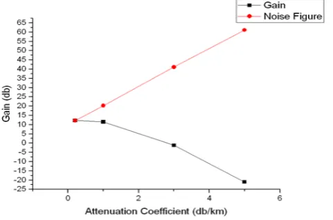
[image:5.595.47.277.378.563.2] [image:5.595.318.559.564.723.2]© 2015-19, IJARCS All Rights Reserved 354 This graph shows the when gain increase attention also
[image:6.595.35.547.53.289.2]increase. Increasing attenuation coefficient from 0.2 to 5 db/ km.
Table. 9.2 Gain Attenuation
[image:6.595.305.539.286.408.2]Increasing attenuation coefficient from 0.2 to 5 db/ km.
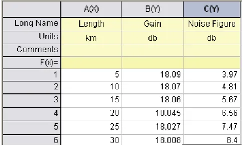
Table. 9.3- Gain Length
This table shows the when Increasing optical fiber from 5 to 5 30 km.
[image:6.595.33.290.348.469.2]Table.9.4- Gain Input Power
Fig 9.11.- Gain Attenuation Coefficient
This graph shows the when gain increase attention coefficient is also increasing.
Table.9.5- Gain Attenuation Coefficient
Table.9.6- Gain Length
This table shows the when gain and length are equal.
V. CONCLUSION
The above talked about dissection work did effectively exhibition connotation change in transmitted power and noteworthy diminishment in dispersion by utilizing pre and post EDFA when contrasted with pre EDFA setup.
[image:6.595.305.549.462.609.2]© 2015-19, IJARCS All Rights Reserved 355 gives better execution (least BER) as contrast with when
utilized for remuneration at collector side. The pick up of the EDFA additionally assumes a critical part in frameworks execution. For arrangement (FBG at the transmitter end), 18 dB pick up has given the best outcomes and for setup (FBG at the collector) 16 dB pick up has given the best outcomes. The entire work speaks to the technique to recuperate the misfortunes which happen because of scattering. The proposed plan System supportive to remunerate the misfortunes utilizing EDFA-FBG show. The Gaussian Light Beam is produced at the info end with client characterized arrangement. The power misfortune and the scattering misfortune is effectively recuperated. We gauged the power and light bar at info, yield and before the collector. The outcome demonstrates that we
got the practically same power 46 μWatt at the yield as
connected at input.
Fiber-optic correspondence in light of its points of interest over electrical transmission, have to a great extent supplanted copper wire interchanges in center systems in the created world. It is discovered that both kind of compensators, DCF and FBG functions admirably. In any case, the FBG compensator outflanks the DCF module in this fast WDM connect with 8 channels for NRZ regulation configuration. Despite the fact that, the outcomes utilizing DCF and FBG are tantamount and a slight distinction between them happens in this examination. Another conclusion made is that as the info energy of laser builds the execution of the system debases. In this way, we presume that for long separation correspondence scattering pay is fundamental.
VI. FUTURE SCOPE
WDM system is the life line of modern day optical fiber network. As depicted by our work, use of multistage EDFA in comparison to single stage. EDFA can provide for significant gains in terms of noise figure and optical power. This improve the perform once of a WDM system considerably as this is progressing research avenue, a lot more is required to cater the ever increasing bandwidth demand. Use of fives grating fibers can provide highly effective dispersion compensation. Also ongoing research in optical amplifier via enhances EDFA to use more sophisticated martial and component either than EDFA. Another research avenue is use of nanotechnology for building loss less optical amplifier. With the gamut of these new technologies on the verge to be introduce, we will see a lot happening in this decode.[12,13,16]
VII.REFERENCES
[1] Tomas Ivaniga, LubosOvsenik, Jan Turan “The Four- An Analysis of 10 Gbits/s Optical Transmission System using Fiber Bragg Grating (FBG).M.A. Othman1, M.M. Ismail2, H.A. Sulaiman3, M.H. Misran4, M.A. Meor Said5, Y.A.Rahim6, A.N. Che Pee7, M.R. Motsidi8 1Centre for Telecommunication Research and Innovation FakultiKej. ElektronikdanKej.Komputer UniversitiTeknikal Malaysia Melaka Hang Tuah Jaya, 76100 Durian Tunggal Melaka, Malaysia 2Fakulti TeknologiMaklumatdanKomunikasi UniversitiTeknikal Malaysia MelakaHang Tuah Jaya, 76100 Durian TunggalMelaka, Malaysia
[2] Dispersion Compensation Using FBG and DCF in 120 Gbps WDM System. Gagandeep Singh, Jyoti Saxena andGagandeep Kaur.International Journal of Engineering Science and Innovative Technology (IJESIT) Volume 3, Issue 6, November 2014 .
[3] Dispersion Compensation and Power Optimization using FBG-EDFA in Optical Communication System. Ramesh Bharti1, Y. C. Bhatt 2 1Ph.D. Research Scholar, Jagan Nath University, Jaipur Professor, Jagan Nath Institute of Technology, Jaipur. International Journal of Recent Research and Review, Vol. VII, Issue 2, June 2014.
[4] Dispersion Compensation and Power Optimization using FBG-EDFA in Optical Communication System. Ramesh Bharti1, Y. C. Bhatt 2 1Ph.D. Research Scholar, Jagan Nath University,Jaipur International Journal of Recent Research and Review, Vol. VII, Issue 2, June 2014 2Professor, Jagan Nath Institute of Technology, Jaipur.
[5] Analysis on dispersion compensation using Post FBG with EDFA. Sameer Anand, P K Raghav, Divya Kumar. International Journal of Scientific & Engineering Research, Volume 4, Issue 9, September-2013 .
[6] Dispersion Compensation Using FBG and DCF in 120 Gbps WDM System. Gagandeep Singh, Jyoti Saxena and Gagandeep Kaur. International Journal of Engineering Science and Innovative Technology (IJESIT) Volume 3, Issue 6, November 2014
[7] Analysis of Pulse Code Modulation Formats in High Speed Optical Transmission System Using FBG and EDFA International Journal of Engineering Science and Innovative Technology (IJESIT) Volume 3, Issue 6, November 2014 . Navneet Kumar1, A.K Jaiswal2, Mukesh Kumar3, Anil Kumar4, Kri. Neha suman5 . IOSR Journal of Electronics and Communication Engineering (IOSR-JECE) e-ISSN: 2278-2834,p- ISSN: 2278-8735.Volume 9, Issue 1, Ver. VI (Feb. 2014).
[8] D.K. Mynbaev and L.L. Scheiner, Fiber-Optic
[9] Communications Technology, Pearson Education, 2001.
[10] G.Gnanagurunathan and F.A.Rahman, “Comparing FBG and DCF as dispersion compensators in the long haulnarrowband WDM systems” 1-4244-03040-5/06/$20.00 ©2006 IEEE.
[11] K.Khairi, Z.Lambak, Norhakimah Md Samsuri, Z.Hamzah and Fong Kok Hann, “Investigation on the Performance of Pre- and Post-Compensation Using Multi-Channel CFBG Dispersion Compensators,” IEEE International RF and Microwave Conference (RFM), 12- 14 December 2011, Seremban, Malaysia.
[12] Devendra Kr. Tripathi, Pallavi Singh, N.K. Shukla and H.K. Dixit, “Performance study in dispersion compensation techniques with Duobinary format at different bit rates,” 2nd International Conference on Power, Control and Embedded Systems, 2012.
[13] J.N.Dike and D.A.Dogbe, “Optimizing the Efficiency of Fiber-Optics Technology in Telecommunications Systems,” IEEE International Conference on Emerging & Sustainable Technologies for Power & ICT in developing society, 2013.
[14] G.H.Patel, R.B.Patel and S.J. Patel,“Dispersion Compensation in 40 Gbps WDM Network using Dispersion Compensating Fiber,” Journal of Information, knowledge and Research in Electronics and Communication Engineering, vol. 2, issue 2, pp. 662-665.
[15] Bo-ning HU, Wang Jing, Wang Wei and Rui-mei Zhao, “Analysis on Dispersion Compensation with DCF based on Optisystem,” 2nd International Conference on Industrial and Information Systems, 2010.
[16] M.A Othman, M.M Ismail, H.A Sulaiman “An analysis of 10 Gbits/s optical transmission sytem using fiber bragg gratting.IOSRJEN.Vol.2,issue 7(July 2012).pp 55-61.
[17] M.Litchinitser, J.Eggleton,and B.Patterson, “Fiber Bragg Gratting for Dispersion Compensation in Transmission theoretical Model and Design Criteria for Nearly Ideal Pulse Recompression”, Journal oflightwave