Understanding Their Interactions with Small-Molecule Liquid Crystal
Solvent
Thesis by Zuleikha Kurji
In Partial Fulfillment of the Requirements for the Degree of
Doctor of Philosophy
California Institute of Technology Pasadena, California
2013
Acknowledgements
This thesis would not have been possible without the aid and support of countless people over the years, and I take immense pleasure in being able to thank them here.
In my case, I feel like I would be remiss in not thanking my thesis committee first: Professors Bill Goddard, Bob Grubbs, Dave Tirrell, and my advisor, Julie Kornfield, who were always available when I had questions or needed advice. I particularly want to thank my original candidacy committee, Bob, Bill, and Julie, who saw me through a pretty rough beginning but had enough faith in me to let me continue. I hope that I’ve justified their decision.
I need to thank my advisor, Julia A. Kornfield. From Julie, I also learned how to be a better scientist: how to listen when data is speaking to you and how to place our research into the big picture. Julie has also, time and time again, has gone above and beyond the call of advisorly duty for me, and I am beyond grateful for her help throughout my graduate career. One of Julie‘s favorite life lessons that she passes down is to “avoid Icky People.” Not only is it good advice that has served me well throughout my graduate career, and, I expect, beyond, but: Julie, you are the farthest from an icky person that I’ve ever known, and I’m proud to have graduated from your group. If I’m ever in a position to manage or mentor others, I hope I can do it with even half the compassion and support that you have. Thank you, Julie, for the time, effort, and energy that you put into my scientific development and my graduate career.
with intellectual collaboration, material assistance in synthesis, and use of his laboratory equipment, Michael also participated, along with Julie and me, in the writing of three collaborative NSF grant proposals, which, when they were funded, became my primary means of support for the last half of my graduate years.
Paul Pirogovsky and Dr. Rohan Hule also made intellectual contributions to this thesis. Paul, Rohan and I worked together on the neutron scattering project(s) described here. Paul also helped design, build, and put together a number of instruments that made this thesis possible, in particular, the temperature controller that I used for my x-ray scattering experiments along with the temperature controller that Paul, Rohan, and I used for our neutron scattering experiments. Dr. Neal R. Scruggs and Dr. Rafael Verduzco overlapped with me on this project during my first years at Caltech, I learned polymer synthesis and deuterated solvent synthesis from them both. I also went on my first neutron scattering trips with Neal and Rafael, where they taught me the ropes during their experiments. Neal and Rafael also initiated the diblock copolymer project that Paul, Rohan and I picked up and ran with – we even used material that Neal and Rafael synthesized during their tenures as graduate students in Julie’s group (Chapter 5). In this vein, I’d also like to thank Dr. Mike Kempe, who I’ve never met, but am grateful to nonetheless, for initiating the SGLCP project in the Kornfield group.
in Taiwan, and Professor Soo-Young Park at Kyungpook National University, in Korea also gave assis-tance and advice up to and including experiments performed in their laboratories.
The Kornfield group has been a place of scientific growth and support for me, and I’m grateful to past and present graduate students and postdocs: Dr. Eric A. Pape, Dr. Charles S. Nickerson, Dr. Derek W. Thurman, Dr. Lucia Fernandez-Ballester, Dr. Neal R. Scruggs, Dr. Rafael Verduzco, Dr. Michael J. Mackel, Dr. Matthew S. Mattson, Dr. R. L. Ameri David, Dr. Ryan Turner, Dr. Shuicui Kimata, Dr. Yan Xia, Dr. Diana Smirnova, Dr, Joyce Huynh, Jeremy Wei, Dr. Keesu Jeon, Dr. Bahar Bingol, Dr. Bradley D. Olsen, Dr. Rohan Hule, Dr. Ladan Foose, Dr. Ruoyu Zhang, Paul Pirogovsky, Iman Hajimorad, Zachary Williams, Artemis Ailianou, Amy Fu, Dennis Ko, Wendy Gu, Boyu Li and Joey Kim. We’ve also been fortunate to work with some talented visitors: Professor Robert Tanner, Professor Soo-Young Park, Dr. Yasutoyo Kawashima, Dr. Manabu Kato, Vanessa Rodriguez, Dr. Dong-yul Lee, Dr. Markus Cudaj, Dr. Adelia Grzbowski, Dr. Wei Sun and Yuchen Zhou. (If I’ve missed any past or present member of the Kornfield group, I sincerely apologize, its not due to your lack of support, it’s just because I’ve been here so long that I’ve overlapped with so many people).
During my graduate career, I had the pleasure of mentoring four Summer Undergraduate Research Fellows (SURFs): Neal Bansal, Lita Yang, Heejae Kim, and Nick Mackay. Not only did each my SURFs contribute to the science that I was able to do, in order to give them meaningful projects, I was required to clarify my understanding of both the big picture and the small details of experiments. This clarity has been incredibly valuable to my research career. Spending time trying to keep undergrads engaged in science was also some of the most fun I’ve had over an oft-difficult career.
multi-tude of chemical order forms that I’ve sent their way; Joe Drew, Ron Koen, and everyone in Chemistry Shipping and Receiving; Rick from the glass shop, Tom Dunn from the electrical shop; Dr. Scott Ross and Dr. David VanderVelde in the Liquid NMR Facility, and Suresh Gupta.
Over the course of my graduate career, I’ve been very grateful for the administrative support from Dian Buchness, Agnes Tong, Laura Lutz-King, Karen Baumgartener and Kathy Bubash. Keeping Julie’s group running smoothly is no small feat, and I’m very grateful for Anne Hormann, Marcy Fowler, and Andrea Arias for, in their turn, keeping the Kornfield lab moving. In particular, Marcy Fowler, whose tenure in Julie’s group overlapped the most with mine, and has become a friend in truth, over the years.
Participating in the Prufrock Cooking and Eating Group, the Caltech Dance Troupe, the Caltech Ballet Club, the Caltech Project for Effective Teaching, and the Caltech Women’s Center have all enriched my life during my tenure as a graduate student here. Thanks are also due to Candace Rypisi, Felicia Hunt, and Portia Harris for their help, friendship, and support during (and after) their tenures as director of the Caltech Women’s Center. The Women’s Center, and especially the Graduate Women’s Discussion Group (affectionately called “Women’s Lunch,” by most of us), was a great emotional stabilizer for me. Thank you also to Lee Coleman for the further emotional support when I needed it.
my love life. I’m not sure how I can ever thank you enough.
So much gratitude to Chris Walker, too, for always being there, even when he was far away. Thanks for the endless understanding and support because, not only did I need every ounce of it, but I appreciated it all so much.
My siblings, Ayisha (the original Dr. Kurji in our family) and Adil (also soon-to-be a Dr. Kurji, if he stays on the path he’s on at the time of this writing), and my brother-in-law, Naheed (neither a Kurji nor a Dr., but we love him anyway), have all laughed with me, been silly with me, and just make me so darn happy most of the time. When I was in undergrad, my Psych 101 professor gave us a thought excercize: choose two people from our lives that we’d most want in the hospital bed next to us if we were both immobilized and could never get away from them. It turns out that this exercise was a way of telling you who in your life that you most want to be like, and I always thought it was telling that I chose Ayisha and Adil. Nowadays, I’d add Naheed and Chris to that list without question.
Abstract
Contents
Acknowledgements iv
Abstract ix
1 Introduction 1
1.1 Background . . . 1
1.1.1 Liquid Crystals . . . 1
1.2 Side-Group Liquid Crystal Polymers . . . 5
1.3 Liquid Crystal Displays . . . 9
1.3.1 Vertically Aligned Nematic LCDs . . . 12
1.3.2 Ferroelectric LCDs . . . 14
1.4 Motivation . . . 16
Bibliography 17
2.1 Abstract . . . 23
2.2 Introduction . . . 23
2.2.1 Background . . . 23
2.2.2 FLC Challenges . . . 26
2.3 Experimental . . . 30
2.3.1 Materials and Instrumentation . . . 30
2.3.2 Methods . . . 32
2.3.3 Synthesis of Side-on SGLCP Homopolymers . . . 32
2.3.3.1 Synthesis of Aldehyde-Containing Butoxybenzoate Mesogen for Silox-ane Coupling . . . 32
2.3.3.2 Siloxane Coupling and 1,2 Polybutadiene Functionalization of Aldehyde-Containing Butoxybenzoate . . . 33
2.3.4 Synthesis of End-on SGLCP Homopolymers . . . 35
2.3.4.1 Synthesis of Vinyl-Terminated Phenyl Pyrimidines for Siloxane Cou-pling . . . 35
2.3.4.2 Siloxane coupling and 1,2 Polybutadiene Functionalization of Vinyl-Terminated Phenyl Pyrimidines . . . 35
2.3.5.1 Thioester cleavage and 1,2-Polybutadiene Functionalization. . . 37
2.3.5.2 Polymer Characterization . . . 38
2.3.5.3 FLC Hosts . . . 39
2.3.5.4 Solutions of Polymers in FLC Hosts . . . 40
2.3.5.5 Polarized Light Microscopy . . . 40
2.3.6 Optical and Electro-optic Measurements . . . 41
2.3.6.1 FLC Properties . . . 41
2.3.6.2 Rise Time and Bistability . . . 41
2.3.7 Small Angle X-ray Scattering of Polydomain FLC Samples . . . 42
2.3.8 Small Angle X-ray Scattering of Aligned Cells . . . 43
2.3.8.1 Sample Cells . . . 43
2.3.8.2 Temperature Controlled Sample Environment . . . 44
2.3.8.3 Small Angle X-ray Scattering . . . 44
2.4 Results . . . 46
2.4.1 Polymer Characteristics . . . 46
2.4.2 Solubility in the FLC matrix . . . 46
2.4.4 Electro-optic Measurements . . . 49
2.4.5 Small Angle X-Ray Scattering of Polydomain Samples: Tilt Angle . . . 53
2.4.6 Small Angle X-Ray Scattering of Aligned Samples . . . 54
2.4.7 Block Coplymers in FLC hosts . . . 57
2.5 Discussion . . . 59
2.6 Conclusions . . . 61
Bibliography 63 3 Polymer-Doped Vertically Aligned Nematic Liquid Crystals 66 3.1 Abstract . . . 66
3.2 Introduction . . . 67
3.2.1 Background . . . 67
3.2.2 Polymer-Stabilzed VA Nematic Cells . . . 69
3.2.3 Polymer-Doped Nematics . . . 70
3.3 Experimental . . . 71
3.3.1 Materials and Instrumentation . . . 71
3.3.2 Methods . . . 73
3.3.2.2 Polymer Characterization . . . 78
3.3.2.3 Elastic and Viscous Constants . . . 79
3.3.2.4 Voltage-Transmission Curves . . . 79
3.3.2.5 Switching Speed Measurements . . . 79
3.3.2.6 Viewing Angle and Contrast . . . 80
3.4 Results . . . 80
3.4.1 Solubility . . . 81
3.4.2 Elastic and Viscous Constants . . . 82
3.4.3 Voltage-Transmission Curves in Cells with Zero Pretilt . . . 83
3.4.3.1 Voltage-Transmission Curve in Rubbed Cells . . . 84
3.4.4 Switching Speed . . . 85
3.4.4.1 Switching Speed Measured in Cell with Zero Pretilt . . . 85
3.4.4.2 Switching Speed Measured in Cell with Small Pretilt (Rubbed Cells) 87 3.4.5 Viewing Angle and Contrast . . . 88
3.4.6 Considerations for Industrial Applicability . . . 90
3.5 Discussion . . . 91
Bibliography 97
4 Structure and Conformation of End-on and Side-on SGLCP Hompolymers in Aligned
Ne-matic Solvents 100
4.1 Abstract . . . 100
4.2 Introduction . . . 101
4.3 Experimental . . . 104
4.3.1 Materials and Instrumentation . . . 104
4.3.2 Methods . . . 106
4.3.2.1 SGLCP Homopolymers . . . 106
4.3.2.2 Synthesis of Perdeuterated 4-Pentyl-4-Cyanobiphenyl (D5CB) . . . 106
4.3.2.3 Polymer Characterization . . . 111
4.3.2.4 Small Angle Neutron Scattering . . . 112
4.4 Results . . . 115
4.4.1 Small Angle Neutron Scattering at Nematic Temperatures . . . 115
4.4.2 Small Angle Neutron Scattering at Isotropic Temperatures . . . 121
4.5 Discussion . . . 127
Bibliography 130
5 Self-Assembly of Coil-SGLCP Diblock Copolymers 134
5.1 Abstract . . . 135
5.2 Introduction . . . 135
5.3 Experimental . . . 138
5.3.1 Materials and Instrumentation . . . 138
5.3.1.1 Polymers . . . 140
5.3.2 Methods . . . 141
5.3.2.1 Polymer Fractionation . . . 141
5.3.2.2 Polymer Characterization . . . 142
5.3.2.3 Transmission Electron Microscopy (TEM) . . . 143
5.3.2.4 Small Angle Neutron Scattering . . . 145
5.4 Results . . . 148
5.4.1 End-on Coil-SGCLP Diblock Copolymers. . . 148
5.4.2 Side-on Coil-SGCLP Diblock Copolymers. . . 153
5.5 Discussion . . . 156
List of Figures
1.1 Liquid crystal phases are intermediate phases between crystalline solid and isotropic liq-uid phases. . . 2
1.2 An example of the molecular structure of a calamitic (rodlike) liquid crystal, 5CB. . . . 3
1.3 Schematic of the nematic, Smectic A and Smectic C* liquid crystalline phases. . . 4
1.4 SGLCPs display anisotropic conformations when dissolved in liquid crystal solvent. . . 6
1.5 A schematic representation of a typical electro-optic LCD cell. . . 11
1.6 Schematics of typical homogenously aligned and vertically aligned LC cells. . . 12
1.7 A schematic representation of the top and side view of a ferroelectric LC cell. . . 15
2.1 Symmetry arguments show that sponaneous polarization is symmetry allowed in the SmC* phase. . . 25
2.2 Chirality causes molecules in the SmC* phase to adopt a helical arrangement. . . 26
2.3 The optimal alignment of smectic layers for a bistable FLC is called ”bookshelf geometry.” 26
2.5 If the driving force to form chevrons is reduced, new layers can nucleate. . . 28
2.6 The structure of the side-on polymer, Polymer1. . . 32
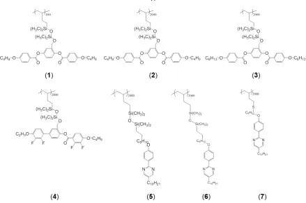
2.7 Side-on and end-on side-groups were designed to be compatible with FLC hosts. . . 47
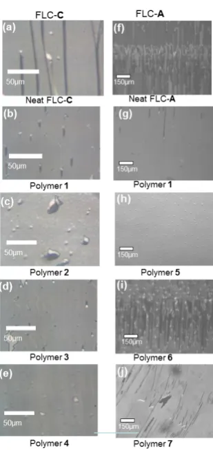
2.8 Polarized optical microscopy shows that our dopants suppress zigzag defects. . . 49
2.9 1.5% of Polymer 1 promotes bistability in host FLC-A. . . 50
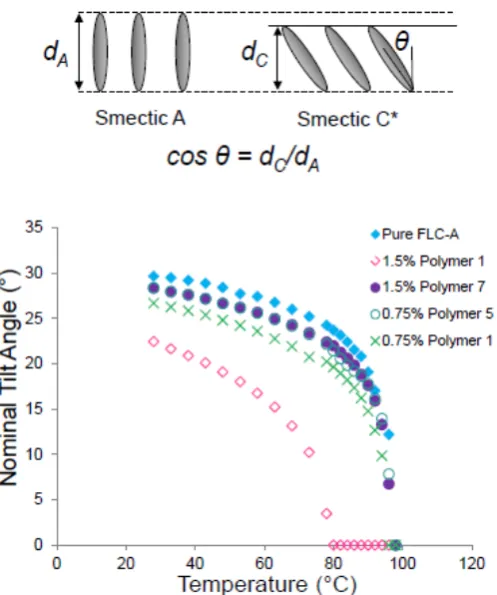
2.10 Addition of 1.5% Polymer 1 appears to delay the tilt of FLC-A as it cools into the Smectic C* phase. . . 54
2.11 Small angle x-ray scattering of bookshelf and chevron samples will give different rocking curves. . . 55
2.12 Addition of 1.0% of Polymer 1 does not affect the Smectic A layer spacing. . . 56
2.13 Addition of 1.0% Polymer 1 appears to distort the chevron structure at 40◦C. . . 57
2.14 Addition of 1.0% Polymer 1 appears to form an asymmetric chevron or tilted bookshelf structure at 40◦C. . . 58
2.15 A likely structure of of side-on and end-on polymer-doped FLC layers. . . 61
3.1 A slight pretilt can dramatically improve the rise time of VA cells. . . 68
3.2 Negative∆SGLCPs can be acheived using the 2,3-difluorophenyl moiety. . . 71
3.3 The synthesis of Polymers 1, 2, and 5 are described elsewhere. . . 72
3.5 The voltage-dependent transmittance of 0.25% Polymers in VA host in unrubbed VA cells. 84
3.6 Voltage-dependent transmission curves of 0.1% polymers in VA host, MLC6886 in rubbed cells. . . 85
3.7 The effect of 0.1% polymer dopant on the transmittance versus rotation angle in VA cells. 86
3.8 Iso-contrast plot of Polymer 3 in VA host in both unrubbed and rubbed cells. . . 89
3.9 Iso-contrast plot of Polymer 3 in VA host in cell annealed from 1.5 to 3 V/µm. . . 90
3.10 Voltage-dependent transmission curves of 0.1% Polymer 5 in VAN host MLC6886, in rubbed cells annealed at 3V/m at a variety of temperatures. Cell failure appears to begin between 60 and 70◦C. . . 91
3.11 Cell failure appears to begin between 60 and 70◦C . . . 91
4.1 Expected conformation and scattering patterns of random coil polymers and side-on and end-on SGLCPs in aligned nematic solvent. . . 101
4.2 Chemical structures and 2-D small angle neutron scattering patterns of side-on and end-on SGLCPs in aligned nematic solvents. . . 116
4.3 1-D horizontal and vertical sector averages (±10◦) of small angle neutron scattering pat-terns of end on and side-on SGLCPs in aligned nematic solvent. . . 118
4.5 1-D horizontal and vertical sector averages (±10◦) comparing two molecular weights of
end-on and two molecular weights of side-on SGLCPS. . . 121
4.6 1-D sector averages (±10◦) of end-on and side-on SGLCPs at nematic and isotropic tem-peratures. . . 122
4.7 1-D sector averages (±10◦) of two molecular weights of side-on SGLCPs at isotropic temperatures. . . 123
4.8 2-D scattering patterns of side-on SGLCPs at high q show a retention of anisotropy at temperaturesabovethe measured TN I of the solvent. . . 123
4.9 1-D horizontal and vertical sector averages of BB-880 in the nematic phase, and at three temperatures above the solvents TN I. . . 124
4.10 1-D horizontal and vertical sector averages of BB-2000 in the nematic phase, and at three temperatures above the solvents TN I. . . 125
4.11 The point at which the anisotropy begins (q*) jumps discontinuously with increasing temperature. . . 126
4.12 A numerical representation of the anisotropy in BB-880 and BB-2000. . . 126
5.1 Matched pairs of coil-SGLCP diblocks have approximately constant SGCLP content, while their polystyrene content increase from 40 to 120 kg/mol. . . 138
5.3 2-D small angle scattering patterns of end-on SGLCP-polystyrene diblock copolymers as polystyrene content increases. . . 150
5.4 1-D horizontal and vertical sector averages of end-on diblocks with increasing PS molec-ular weights. . . 151
5.5 Comparison between positively-stained and unstained TEM micrographs of two end-on SGLCPs. . . 153
5.6 2-D scattering patterns of side-on SGLCP-polystyrene diblock copolymers as polystyrene content increases. . . 154
5.7 1-D horizontal and vertical sector averages (±10◦) of side-on diblocks with increasing polystyrene molecular weights, . . . 155
List of Schemes
1.1 Placing electron-withdrawing fluorine groups asymmetrically on rings that lie along the long axis of the molecules creates transverse dipole, giving negative∆nematic LCs. . 14
2.1 The synthesis of the 3,5-di(4-butoxybenoate)-benzaldehde side group, “BB.” . . . 34 2.2 The “BB” side group is grafted onto the pendant vinyl groups of 1,2-polybutadiene by
platiunm catalyzed hydrosilation of its aldehyde group. Attaching the mesogen at a middle point in the molecule leads to a side-on SGLCP. . . 34 2.3 Williamson ether synthesis of end-on phenyl pyrimdine mesogenic side groups. . . 35 2.4 Siloxane coupling, first to vinyl-terminated mesogen, then to 1,2-polybutadiene. . . 36 2.5 The synthesis of the protected thiol mesogenic phenyl pyrimidine side group. . . 37 2.6 Thioester cleavage into thiol, followed by direct radical-catalyzed thiol-ene coupling
with 1,2-polybutadiene. . . 38
3.1 The synthesis of siloxane-linked SGLCP homopolymer with cyclohexylcyclohexenyl-2,3-difluorophenyl transverse-dipole side-group. . . 74 3.2 The synthesis of silane-linked SGLCP homopolymer with transverse-dipole
biphenyl-cyclohexyl side groups. . . 76 3.3 The synthesis of siloxane-linked SGLCP homopolymer with transverse-dipole terphenyl
List of Tables
2.1 Three FLC hosts were designed by LC Vision to have polarization around∼20nC/cm2, and similar viscosity and dielectric constants, but varying in pitch. . . 39
2.2 Rise times of 1% polymers in three FLC hosts. . . 52
2.3 Polymers have little effect on FLC host polarization, dielectric constant and viscosity. . . 52
3.1 Electric spectroscopy results for 0.25% by weight of Polymers 1, 3 and 4 in pure VA host (MX40424) . . . 82
3.2 Response time of pure VAN host (MLC6886) and 0.25% polymer-doped VAN mixtures in 4µm unrubbed cells, annealed at 3 V/µm. . . 86
3.3 Response time of pure VA host (MLC6886) and 0.1% polymer-doped VA mixtures in 4 µm unrubbed cells, annealed at 3 V/µm. . . 87
3.4 Response time of pure VA host (MLC6886) and 0.25% and 0.1% polymer-doped VA mixtures in 4µm rubbed cells, annealed at 3 V/µm. . . 88
4.2 Aspect ratios of end-on “CB4”) and side-on (“BB”) SGLCPs based on 2D scattering patterns, 1-D reduction and fitting to the shape-independent Debye function . . . 120
5.1 Diblock prepolymers with near-constant polybutadiene (PB) and polystyrene (PS) blocks that vary from 40 to 120 kg/mol (DP = 380 to 1140) were synthesized by the Center for Nanophase Materials at ORNL. . . 140
5.2 End-on and side on coil-SGLCP diblock copolymers were synthesized from prepolymers with polystyrene (“PS”) and polybutadiene (“PB”) blocks. . . 141
5.3 Chain shape parameters for end-on coil-SGLCP diblock copolymers in the parallel direc-tion are derived from Guinier fits, and in the perpendicular direcdirec-tion are derived by fitting a combination of the Guinier and Lorentzian shape-independent models. . . 152
5.4 Micelle diameters determined from ImageJ analysis of stained and unstained TEM mi-crographs of end-on coil-SGLCP diblock copolymers. . . 153
5.5 Chain shape parameters for side-on coil-SGLCP diblock copolymers in the parallel di-rection are derived by fitting a combination of the Guinier and Lorentzian models, while parameters in the perpendicular direction are derived from Guinier fits. . . 155
Chapter 1
Introduction
1.1
Background
1.1.1 Liquid Crystals
Liquid crystal phases (Figure 1.1, center) are intermediate phases of matter that fall between the solid, or crystal, phase and the isotropic liquid phase. The crystalline phase (Figure 1.1, left) and the liquid phase (Figure 1.1, right) are two of the three most familiar states of matter: in a crystalline solid the constituent molecules are constrained in both their orientation and position, while in a liquid they lack both the orientational constraint and long-range correlation [1]. Molecules in a solid thus possess both orientational and positional order, while the molecules in a liquid have neither. The lack of rigid ar-rangement of molecules in the liquid phase means they are free to randomly diffuse, allowing liquids to flow, take the shape of their container, and be deformed in response to weak outside forces [1]. The molecules in liquid crystal phases also flow, like the molecules in a liquid, but possess a small amount of additional order, like the molecules in a solid (Figure 1.1) [1].
Figure 1.1. In the solid phase, the molecules (represented here by gray rods) have both orientational and positional order. When heated, certain molecules pass through a progression of partially ordered liquid crystalline phases, one of which is shown here: in this case losing positional order, but remaining oriented in a preferred direction called the director, n. After further heating, the molecules become liquid – having neither long-range positional order nor orientational correlations.
in the transition to the liquid crystal phase. This small amount of additional order retained in the liquid crystalline phase is then lost at the liquid crystal-to-liquid phase transition
Certain molecules, or families of molecules, are more likely to have liquid crystalline phases. Specifi-cally, two conditions are generally satisfied for a molecule to display an LC phase: a rigid, anisotropic core gives the molecule order while flexible tail group(s) allow the molecules to flow. Calamitic liquid crystals, for example, are rigid, rod-shaped molecules with an elongated conformation (i.e., significantly longer than they are wide) that allows for preferential alignment of their long axes along one spatial di-rection. The average direction of the long axes of the molecules in an LC phase is called the director (n) (Figure 1.1, middle). Energetically, when elongated molecules are aligned parallel to each other they tend to have stronger attractive forces
which has an LC phase at room temperature, making it a frequently studied LC. 5CB, made up of a rigid biphenyl core, a flexible hydrocarbon tail, and a permanent dipole moment (contributed by the cyano-moiety), has an anisotropic, rodlike structure with a long axis of 20 ˚A and a short axis of 5 ˚A.
Figure 1.2. 5CB, calamitic (rodlike) liquid crystal widely used in laboratory studies, contains a rigid core and a flexible tail and is in a liquid crystalline phase at room temperature. 5CB is anisotropic: one axis (called the “long axis”) is longer than the other (called the “short axis”). Calamitic LCs like 5CB are often represented as rod-like cartoons in schematic representations.
There are many liquid crystalline phases, but there are three, in particular, that are relevant to this the-sis, the nematic, the smectic A (SmA) and the smectic C (SmC) phases (Figure 1.3). Molecules in the nematic LC phase (Figure 1.3, left), the simplest LC phase, only have orientational order: the nematic molecules point on average along a common axis, the director (n). Smectic liquid crystalline phases have orienational order, but also possess positional order: the molecules are arranged in layers. In the SmA phase (Figure 1.3, center) the molecules in the layers point, on average, parallel to the layer nor-mal, while in the SmC phase (Figure 1.3, right) they are tilted off that axis. Unlike some other smectic phases, the molecules in the SmA and SmC phases can randomly diffuse within each plane – no posi-tional order thus exists within these planes [1].
Figure 1.3. Molecules in the nematic liquid crystalline phase display orienational order. The director, n, is parallel to the average direction of molecular alignment. Smectic liquid crystalline phases are found at lower temperatures than the nematic phase and are defined by the formation of well-defined layers (positional order) as well as having their molecules point on average in a one direction (orientational order). In the smectic A phase, the director is paralell to the layer normal, while in the smectic C phase, the director is tilted.
smectic LCs is typically around 20°, corresponding to order parameters of 0.6 and 0.8, respsectively. The strength of LC order, and hence the value of the order parameter, is related to the anisotropy of physical properties displayed by LCs, such as birefringence or dielectric anisotropy [2].
Liquid crystal displays (LCDs), arguably the most well-known application of LCs, are made possible due to the coupling of order to fluidity: the LCs anisotropic dielectric properties make LC’s anisotropic optical properties accessible, while LC fluidity allows for the orienting electric fields to be small (i.e., readily accessible) [7]. In these cases, the alignment of the bulk LC in the applied electric field is dictated by a combination of the interactions between the LC and the field, the aligning surface and the elastic interactions with other LC molecules [7]. A more detailed description of commercial LCDs can be found in section 1.1.3.
1.2
Side-Group Liquid Crystal Polymers
Side-group liquid crystal polymers (SGLCPs) are flexible-chain polymers that are functionalized with liquid crystalline (LC) side-groups. Because the side-groups contain a liquid crystal mesophase-forming group, called a mesogen, the SGLCP exhibits unique properties that arise from the coupling of the ori-entational order inherent in the LC side group to the entropically driven flexibility of the polymer back-bone [8]. Ideally, then, SGLCPs can combine the functionality of conventional LCs with the advantages of polymer systems [8] [9] [10] [11]. SGLCPs are soluble in LC phases, while random-coil polymers are typically not [12]. This allows SGLCPs to be used as additives in LCs to stabilize structure, or enhance electro-optical response.
In contrast to random coil polymers in good solvents (Figure 1.4, left), SGLCPs adopt an anisotropic conformation upon dissolution in a small-molecule LC (Figure 1.4, center, right) [13]. The extent of the anisotropy depends on the LC order parameter, which in turn depends on the temperature of the system. The ability to control polymer conformation using temperature has led to a number of possible applications including shape-memory LCs systems [14] [15] [16] [17] [18].
mate-Figure 1.4. When dissolved in small molecule nematic liquid crystal, random-coil polymers (left) dis-play isotropic conformations (Rk = R⊥), while end-on SGLCPs, with mesogens perpendicular to the
polymer backbone (center), typically show an oblate conformation (Rk < R⊥), and side-on SGLCPs,
with mesogens parallel to the polymer backbone (right), typically show a prolate conformation (Rk >
R⊥).
rial properties: the polymer backbone, the mesogenic side group –both its chemical structure and the manner in which it is attached to the backbone (emphe.g., either at the center or the end of the meso-gen) and, finally, the chemical structure and length of group that links the side groups to the polymer backbone. One of the most common (and historical) ways to make an SGLCP is the functionalization of a polysiloxane backbone, a system first devised by Finkelmann et al.[19]. Mesogenic side groups are grafted onto already synthesized polyalkylsiloxane backbones (for example poly(methylhydrosiloxane)) using platinum catalyzed hydrosilation to attach a side group to as many silane hydrogens as desired, often resulting in a mesoenic group in nearly every repeat group. Polysiloxane SGLCPs are generally transparent and have low glass transition temperatures, making them ideal for many applications [20].
hydrocarbon backbones: 1,2-polybutadiene’s pendant vinyl group, for example, can be modified with mesogenic side groups using a variety of chemistries [9] [21] [22]. The polybutadiene is polymerized by anionic polymerization, making high molecular weight and low polydispersity index SGLCPs accessi-ble. Increasing polymer molecular weight generally allows for the use of lower polymer concentrations to achieve similar effects, without the concomitant increase in rotational viscosity (and hence lower switching speed) that comes with increasing polymer concentration [23]. Polymer analogous chemistry using the 1,2-polybutadiene polymer backbone is thus the synthetic method of choice for the SGLCPs reported in this thesis.
Mesogen-containing monomers with polymerizable groups can also be directly polymerized into SGLCPs. Polyacrylates and polyolefins are common hydrocarbon backbones polymerized this way. This method yields lower molecular weight polymer (on the order of 2 to 20 kg/mol), but offers a broader choice of side group and spacers.
Rodlike mesophase-forming side groups can be attached to the polymer backbone, either terminally, giving “end-on” SGLCPs, or at their center, giving “side-on” SGLCPs. The molecular structure of the side groups is chosen both to confer liquid crystalline behavior to the SGLCP and to be soluble in small molecule LC solvents. Much like small molecule LCs, SGCLP side groups are typically made up of rigid core combined with a flexible part either an alkyl spacer or an alkyl tail, or both. A common method to achieve good solubility in small molecule LC solvents is to use side groups with structures similar to that of the solvent [19]. For example, the Kornfield group has used cyanobiphenyl-based side groups in SGLCPs designed to dissolve in 5CB [8] [9] [13] [22] [24] [12].
in the bulk [10]. Decoupling the motions of the mesogens from the backbone gives greater entropy to the system, making the LC mesophases more thermally accessible and decreasing the polymer’s glass transition temperature (Tg). In addition, the increased mobility leads to a greater entropy of solvation, making SGLCPs more soluble in small molecule LCs than their analogous main chain LCPs [23].
When dissolved in an LC solvent, the thermodynamic behavior of the polymer backbone is quite differ-ent from that of the mesogenic side groups: the backbone is driven by maximization of conformational entropy to be disordered and coil-like, while side groups are driven by maximization of their enthalpic interactions to self-assemble into ordered structures [10]. When an SGLCP is dissolved in a liquid crys-tal solvent, the order of the LC along with interactions between adjacent side groups can affect flexibility and orientation of the polymer chain segments [23]. For example, in a nematic solvent, the mesogens in end-on SGLCP typically lie perpendicular to the polymer backbone, resulting in the polymer having a larger radius of gyration in the direction perpendicular to the director (Figure 1.4, center). This disclike, spheroid conformation is called “oblate.” A side-on SGLCP (with mesogens parallel to the backbone), on the other hand, adopts a prolate ellipsoidal, or egg-shaped, conformation (Figure 1.4, right).
When systems include both macromolecules and small molecule LCs, they are called “LC gels,” and are attractive to many researchers that hope to marry liquid crystals’ optical and responsive properties with polymers’ mechanical strength and ease-of-processing. LC gels that also show fast reorientation dynamics, and good optical uniformity, are attractive targets for the LCD industry [25], [26], [27]. Other potential applications of LC gels include miniactuators [28], [29], [30], sensors [31] [32] and optical data storage [33].
the blocks and the solvent and the penalty associated with the stretching of the polymer chain across the interface. As a result, the domain size is set by the molecular weight of each block and can easily be in the 10 nm range [35].
Flexible coil polymers are generally insoluble in LCs, and thus provide a driving force for phase segre-gation when covalently linked to SGLCPs. Coil-SGLCP block copolymers (BCPs) exhibit ordered mor-phologies that reflect the interplay of microphase segregation and LC order. Just as with conventional block copolymers, unfavorable thermodynamic interactions between the two blocks cause them to form microstructures that minimize the insoluble block’s contact with the LC solvent. When the other block is liquid crystalline, the swollen material can show order at many length scales: from the nanometer scale (interaction on the molecular level) to upwards of hundreds of nanometers (BCP self-assembly).
Block copolymer self-assembly in LC solvent has been investigated for producing LC gels. For example, the Kornfield group has produced LC gels using the association of the end blocks of a polystyrene-SGLCP-polystyrene triblock copolymer in a small molecule nematic LC solvent as the driving force for gelation [9]. Because of their intrinsic nematic order, the SGLCP midblocks are soluble in the small molecule LC solvent, while the polystyrene end groups are less soluble and tend to aggregate together to reduce contact with the solvent – leading to a three-dimensional polymer network in the LC solvent. The macromolecular structure of these physical gels is produced in a controlled way, resulting in materials with regular and thermally reversible
1.3
Liquid Crystal Displays
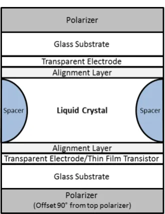
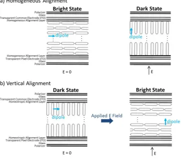
simi-lar, regardless of application (Figure 1.5). A generic LC electro-optic cell is made up of LC molecules sandwiched between two parallel glass plates spaced from 1 to 25µm apart, using uniform spacer beads (Figure 1.5). The inner surfaces of the glass substrates are first treated with indium tin oxide (ITO), creating a transparent electrode. When a voltage is applied across the two ITO electrodes, the dipoles of LC molecules will align in the direction of the electric field, reorienting the LC molecules from their voltage-off state. In fact, it was, in part, the discovery of ITOs use as a transparent electrode during the second world war that made modern LCDs possible: previously, because of their opacity, metal electrodes could only apply a field perpendicular to the direction of the light, greatly limiting potential opto-electronic applications [4]. After the ITO layer is added, a very thin polymer alignment layer is spin-coated onto the electrode (or transistor array) and is physically rubbed in one direction: this treat-ment confers macroscopic orientational order to the LCs in their voltage-off state. Depending on the polymer and the surface treatment, the LCs can orient either parallel to the surface (homogenous’ or “planar” alignment, Figure 1.6a), or perpendicular to the surface (homeotropic or “vertical alignment (VA)” Figure 1.6b). The cooperative ordering of LCs amplifies molecular level orientation at the an-choring surface, conferring the desired alignment to the bulk. In fact, the main differences in the various types of commercial LCDs are the type of LC material and the type and direction of the alignment layer.
Nearly 95% of LCDs on the market use nematic LCs [36]. At present, there are two main approaches used in the manufacture of nematic liquid crystal displays: the twisted nematic (TN) LCD, which uses homogenous alignment (HA, Figure 1.6a), and vertically aligned nematic (VAN) LCDs (Figure 1.6b). Another type of LCD that has shown promise in the laboratory but has yet to be widely commercial-ized, uses ferroelectric liquid crystals (FLC) LCD which, instead of nematic LCs, uses homogeneously aligned LCs in the smectic C phase.
Figure 1.5. A schematic representation of a typical electro-optic LC cell. The LC layer is sandwiched between substrates that are treated with a transparent electrode, followed by a polymer alignment layer that constrains the LC to desired alignment. In a commercial LCD the bottom electrode layer is replaced by a thin-film transistor array that addresses each pixel electronically. A color filter is also placed in between the top electrode and the glass substrate to provide color to the pixels of a commercial LCD.
Figure 1.6. (a) Schematic of a typical homogenously aligned LC cell. In the voltage-off state, the cell is in the bright state, and when voltage is applied the molecules reorient to align their dipoles (blue arrows) in the direction of the field, resulting in homeotropic alignment, and an optical dark state. A commercial twisted nematic (TN) display, is very similar to this, but the molecules in the voltage-off state (right) are arranged in a helix, instead of the simplified version shown here. The helix untwists and aligns homeotropically (as shown here, right) when voltage is applied. (b) A vertically aligned nematic (VAN) displays voltage-off state, on the other hand, consists of homeotropically aligned molecules, resulting in a dark state. When a voltage is applied, the molecules reorient to align their dipoles in the direction of the applied field. Because the VAN molecules dipoles are transverse to the molecular axis, this leads to a homogeneous (parallel) alignment, resulting in the bright state when voltage is applied.
1.3.1 Vertically Aligned Nematic LCDs
used in VA nematic displays. In contrast to homogeneously aligned nematic cells, the dipole of these LC molecules is perpendicular to their molecular axis (thus perpendicular to the glass surface). When an electric field is applied, the LC molecules reorient such that their dipoles rotate toward the direction of the electric field (i.e., their molecular axes rotate toward being parallel to the glass plates), resulting in a state that is birefringent under crossed polars: the bright state (Figure 1.6b, right, note arrows labeled dipole and E).
The major commercial advantage of the VA mode, is that VA nematic displays have high contrast (large difference between light transmission in the dark state relative to that in the light state), because the LC is almost completely vertically at zero voltage, giving the cell an excellent dark state under crossed polarizers (Figure 1.6a, right). However, the very high contrast of VAN-LCDs comes at expense of the response time of the display: a pixel in a current VA nematic display takes on the order of 100 ms [2] to switch (rise time + fall time), compared to less than 20 ms for a TN display [37].
On a molecular level, the key to successful VAN devices is the transverse dipole (Scheme 1.1). The ad-dition of groups that give transverse dipoles, for example the 2,3-difluorphenyl group (Scheme 1.1), also tends to increase the melting temperature of the system, for example, The structures shown in Scheme 1, for example have strongly negative dipoles (ranging from -2.7 for3to -8.6 for8) but many of them are crystalline solids at room temperature with melting points range from 45◦C for 1 to 99◦C for7(adding a transverse dipole tends to increase the melting temperature). When the pure compounds do have a room temperature nematic phase, they tend also to have high viscosity, leading to slow switching speeds. Synthesis of negative∆nematic LCs with low viscosity (e.g., 8 in Scheme 1) was a breakthrough attributed to Merck [38] [39].
Scheme 1.1. Placing electron-withdrawing fluorine groups asymmetrically on rings that lie along the long axis of the molecules creates transverse dipole, giving negative∆nematic LCs.
1.3.2 Ferroelectric LCDs
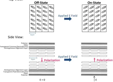
In addition to LCDs that use nematic LCs, ferroelectric liquid crystals (FLCs) can also be used in LCDs. A ferroelectric material is defined as one that possesses a spontaneous electric polarization in the absence of an external electric field (Figure 1.7, pink arrow). Because of this property, ferroelectric liquid crystals have significantly faster switching speeds, dramatically lower power consumption and superior resolution when compared to nematic LCDs [40]. Chiral molecules in the Smectic C phase (tilted, layered orientation, Figure 1.3, left) have a reduced symmetry that lead to a spontaneous polarization.
for the lifetime of the display device. Cells in poor alignment are marked by the formation of “zigzag defects,” a light-leaking defect that renders the cell effectively useless in an LCD. The difficulty in achieving perfectly aligned FLC cells limits the size and yield of available FLC displays.
Figure 1.7. A schematic representation of the top and side view of an FLC cell. When chiral molecules in the Smectic C phase (a tilted, layered orientation) are confined in an FLC cell with homogenous alignment, they exhibit a spontaneous polarization. When a vertical electric field is applied, their po-laization aligns parallel to the field and the molecules switch orientations to the opposite tilt. Because this switching occurs in the same plane, “dark” and “bright” states can be determined by placement of the polarizer. In-plane switching also results in a very good viewing angle.
Many groups have also attempted to utilize polymers to stabilize FLCs byin situ polymerization of monomers in an FLC host [41] [27] [42].In situpolymerization of FLC stabilizing elastomers generally uses anywhere from 5% to 25% polymer to stabilize the alignment. Polymerization occurs while the monomer is aligned, typically with an applied electric field, an additional, and often onerous, manufac-turing step. The presence of the cross-linked network often leads to an increase in switching speed and an increase in driving voltage required to switch the cross-linked network [42].
dopants in FLC host, suppressing zigzag defects without sacrificing speed or optical uniformity.
1.4
Motivation
This work aims to further the molecular-level understanding of LC-polymer interactions, by examin-ing the changes in bulk LC properties upon very specific modifications to side-group chemistry. The structure, conformation, and material property enhancement of a variety of types of LCs upon addi-tion of soluble SGLCP homopolymers was investigated, This work has lead to the concept of using homogenously dissolved SGCLP homopolymers at low concentration as“dopants” that can enhance the optic and electro-optic properties of a variety of LC types. Among the targeted structure modifications are molecular weight, side-onvs. end-on attachment, linking group type, alkyl spacer length, dipole direction, dipole strength and polymer endgroup.
Bibliography
[1] Peter J. Collings. Liquid Crystals. Princeton University Press, Princeton, NJ, 1 edition, 1990.
[2] Deng-Ke Yang and Shin-Tson Wu. Fundamentals of Liquid Crystal Devices. John Wiley & Sons Ltd, Chichester, 2006.
[3] Yiqun Bai and Nicholas L. Abbott. Recent advances in colloidal and interfacial phenomena in-volving liquid crystals.Langmuir: The ACS Journal of Surfaces and Colloids, 27(10):5719–5738, May 2011.
[4] Timothy J. Sluckin, David A. Dunmur, and Horst Stegemeyer.Crystals that Crystals, Flow: Clas-sic papers from the history of liquid crystals. Taylor & Francis, London, 2004.
[5] H. Lin, M. Khan, and T. Giao. Dynamic Liquid Crystal Hot Spot Examination of Functional Failures on Production Testers. InProceedings from the 20th International Symposium for Testing and Failure Analysis, page 81, 1994.
[6] David Burgess. Liquid Crystal Hotspot Detection. http://www.acceleratedanalysis.com/LC hotspotdetection procedure.html.
[7] Scott J. Woltman, Gregory D. Jay, and Gregory P. Crawford. Liquid-crystal materials find a new order in biomedical applications. Nature Materials, 6(12):929–38, December 2007.
[9] Michael D. Kempe, Neal R. Scruggs, Rafael Verduzco, Jyotsana Lal, and Julia A. Kornfield. Self-assembled liquid-crystalline gels designed from the bottom up. Nature Materials, 3(3):177–82, March 2004.
[10] Jun-Feng Zheng, Zhen-Qiang Yu, Xin Liu, Xiao-Fang Chen, Shuang Yang, and Er-Qiang Chen. Side-chain liquid-crystalline polymers based on flexible rod-like mesogen directly attached to backbone. Journal of Polymer Science Part A: Polymer Chemistry, 50(24):5023–5031, Decem-ber 2012.
[11] Xuzhou Yan, Feng Wang, Bo Zheng, and Feihe Huang. Stimuli-responsive supramolecular poly-meric materials. Chemical Society Reviews, 41(18):6042–65, September 2012.
[12] Neal R. Scruggs and Julia A. Kornfield. Synergistic ordering of side-group liquid crystal poly-mer and small molecule liquid crystal: order and phase behavior of nematic polypoly-mer solutions. Macromolecular Chemistry and Physics, 208(1920):2242–2253, October 2007.
[13] Michael D. Kempe, Julia A. Kornfield, and Jyotsana Lal. Chain anisotropy of side-group liquid crystalline polymers in nematic solvents. Macromolecules, 37(23):8730–8738, 2004.
[14] Sawa Yoshiki, Kenji Urayama, and Toshikazu Takigawa. Temperature-responsive bending of nematic elastomers with hybrid molecular alignment. Molecular Crystals and Liquid Crystals, 549(1):106–112, October 2011.
[15] Marc Behl and Andreas Lendlein. Actively moving polymers. Soft Matter, 3(1):58, 2007.
[16] Andreas Lendlein, Annette M Schmidt, and Robert Langer. Segments showing shape-memory properties.Proceedings of the National Academy of Sciences, 98(3):842–847, 2001.
[18] Suk-kyun Ahn and Rajeswari M. Kasi. Exploiting microphase-separated morphologies of side-chain liquid crystalline polymer networks for triple shape memory properties. Advanced Func-tional Materials, 21(23):4543–4549, December 2011.
[19] H Finkelman, H.-J. Kock, and G Rehage. Phase studies of liquid crystalline side chain polymers mixed with low molar mass liquid crystals of similar structure. Mol, 89:23–26, 1982.
[20] Hong Yang, Ming-Xia Liu, Yue-Wei Yao, Ping-Yang Tao, Bao-Ping Lin, Patrick Keller, Xue-Qin Zhang, Ying Sun, and Ling-Xiang Guo. Polysiloxane–based liquid crystalline polymers and elastomers Prepared by thiol–ene chemistry. Macromolecules, 46:3406–3416, 2013.
[21] Michael D Kempe, Julia A. Kornfield, Christopher K. Ober, and Steven D. Smith. Synthesis and phase behavior of side-group liquid crystalline polymers in nematic solvents. Macromolecules, 37:3569–3575, 2004.
[22] R. L. Ameri David and Julia A. Kornfield. Facile, efficient routes to diverse protected thiols and to their deprotection and addition to create functional polymers by thiol–ene coupling. Macro-molecules, 41(4):1151–1161, February 2008.
[23] Michael David Kempe. Rheology and dynamics of side-group liquid crystalline polymers in ne-matic solvents. Phd thesis, California Institute of Technology, 2003.
[24] Rafael Verduzco, Neal R. Scruggs, Samuel Sprunt, Peter Palffy-Muhoray, and Julia A. Kornfield. Director dynamics in liquid-crystal physical gels.Soft Matter, 3(8):993, 2007.
[26] Chi-Yen Huang, Wen-Yi Jhuang, and Chia-Ting Hsieh. Switching of polymer-stabilized vertical alignment liquid crystal cell. Optics express, 16(6):3859–64, March 2008.
[27] Hideo Fujikake, Tahito Aida, Jun Yonai, Hiroshi Kikuchi, Masahiro Kawakita, and Kuniharu Tak-izawa. Rigid formation of aligned polymer fiber network in ferroelectric liquid crystal. Japanese Journal of Applied Physics, 38(9):5212–5213, 1999.
[28] M.-H. Li, P. Keller, J. Yang, and P.-A. Albouy. An artificial muscle with lamellar structure based on a nematic triblock copolymer. Advanced Materials, 16(21):1922–1925, November 2004.
[29] H. Meng. A brief review of stimulus-active polymers responsive to thermal, light, magnetic, elec-tric, and water/solvent stimuli.Journal of Intelligent Material Systems and Structures, 21(9):859– 885, May 2010.
[30] Christian Ohm, Christophe Serra, and Rudolf Zentel. A continuous flow synthesis of micrometer-sized actuators from liquid crystalline elastomers. Advanced Materials, 21(47):4859–62, Decem-ber 2009.
[31] Michael I Kinsinger, Maren E Buck, Nicholas L Abbott, and David M Lynn. Immobilization of polymer-decorated liquid crystal droplets on chemically tailored surfaces. Langmuir: The ACS Journal of Surfaces and Colloids, 26(12):10234–42, June 2010.
[32] Dong-Yul Lee, Jung-Min Seo, Waliullah Khan, Julia A. Kornfield, Zuleikha Kurji, and Soo-Young Park. pH-responsive aqueous/LC interfaces using SGLCP-b-polyacrylic acid block copolymers. Soft Matter, 6(9):1964, 2010.
[34] Anne de Cuendias, Roger C. Hiorns, Eric Cloutet, Laurence Vignau, and Henri Cramail. Con-jugated rod-coil block copolymers and optoelectronic applications. Polymer International, 59(11):1452–1476, November 2010.
[35] Yuefei Tao, Bryan McCulloch, Suhan Kim, and Rachel A. Segalman. The relationship between morphology and performance of donor-acceptor rod-coil block copolymer solar cells.Soft Matter, 5(21):4219, 2009.
[36] Peter J. Collings and Michael Hird. Introduction to Liquid Crystals: Chemistry and Physics. Taylor & Francis, London, 2001.
[37] Type of LCD Panel Technology. http://guide2lcdtv.com/2010/07/lcd-tv-panel-technology-comparison/, 2010.
[38] Matthias Bremer and Lars Lietzau. 1,1,6,7-Tetrafluoroindanes: improved liquid crystals for LCD-TV applicationw.New Journal of Chemistry, 29:72–74, 2005.
[39] Krause J. Plach H. J. Weber G. Reiffenrath, V. New liquid-crystalline compounds with negative dielectric anisotropy. Liquid Crystals, 5(1):159–170, 1989.
[40] Sven T. Lagerwall. Ferroelectric and Antiferroelectric Liquid Crystals. Wiley-VCH, Weinheim, 1999.
[41] Kyehun Lee and Sin-Do Lee. Fast linear electro-optical switching ferroelectric liquid crystals properties of polymer-dispersed. Applied Physics Letters, 64(6):718–720, 1994.
Chapter 2
Polymer-Doped Ferroelectric Liquid
Crystals
Michael D. Wand of LC Vision contributed to the experiments discussed in this chapter by formulating the FLC hosts. I synthesized the polymers. Together we analyzed them optically and electro-optically at LC Vision. We also thank Noel Clark for his insight into FLC physics and two members of his group, Chenhui Zhu and Yongqiang Shen, for advice about surface stabilized x-ray cells. Torsten Hegmann and his group at the University of Manitoba carried out the capillary (polydomain) x-ray experiments. We are also grateful to the Tirrell lab for use of their spin-coater.
2.1
Abstract
A family of polymer dopants for Ferroelectric Liquid Crystals (FLCs) has been discovered that over-comes the main technical obstacles to large-scale application of FLC devices: manufacturing and stabi-lizing properly aligned cells. Side-on and end-on side-group liquid crystal polymers that were soluble in an FLC host were identified. These polymer-doped FLCs suppressed zigzag defects yet retained the fast electro-optic responses, good contrast and appropriate tilt angle required for display devices. Side-on SGLCPs were also demSide-onstrated to rapidly and robustly adopt an alignment that enabled bistable switching providing the first glimpse into the consequences of orientational coupling in chiral smectic LCs.
2.2
Introduction
2.2.1 Background
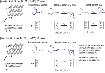
A ferroelectric material is defined as one that possesses a spontaneous electric polarization in the absence of an external electric field. Ferroelectricity can be achieved whenchiralLC molecules self-organize into a chiral Smectic C phase (SmC*), a tilted, layered organization (Figure 2.1b). The tilt of the long axis of the molecules is necessary for a spontaneous dipole to occur in the bulk: if the long axis of the molecules simply points along the layer normal, there is no spontaneous dipole in the plane of the layers. The reduced symmetry of chirality allows for the discrimination between two different tilted states that have opposite dipole directions [1].
elements of every property of the material (Neumann’s principle) [1]. Spontaneous polarization in a liquid crystal phase must thus share the same symmetry elements as the liquid crystal phase. In the SmC* phase, because the chiral mesogens are oriented in tilted layers, the system possesses only a unique twofold rotation axis, C2y (chirality eliminates the mirror plane, (Figure 2.1, right) and the inversion center that are present in an smectic C phase). If one imagines the three components of the polarization vectors (Figure 2.1a,b), a 180◦ rotation about the C2-axis, in this case the y-axis, would
reverse the signs of the components in the x and z directions. Since both the SmC and SmC* phasesare symmetric about this axis, the polarization in these two directions must be zero (Figure 2.1). However, polarization in the y direction is invariant with respect to this rotation, and, thus, a non-zero Pysymmetry is allowed. Because the molecules in the SmC* phase are chiral, there are no other symmetry operations that in turn disallow the polarization in the y direction (Figure 2.1b, right), in contrast to the SmC phase for which reflection symmetry across the xz plane disallows the polarization in the y direction (Figure 2.1a, right). The reduced symmetry of SmC* thus allows for the existence of a permanent dipole moment parallel to its C2-axis. In turn, the permanent dipole can be switched by reversing the
polarity of an applied electric field [2].
Figure 2.1. (a) The achiral SmC phase has orientational and positional order (moleclues are organized into tilted layers). Symmetry arguments show that polarization is not permitted in this phase. (b) Chirality reduces the SmC* phase’s symmetry to one C2-axis. Spontaneous polarization in the plane of
the C2-axis is thus permitted by symmetry.
surface stabilized ferroelectric liquid crystal (SSFLC), conceived by Noel Clark and Sven Lagerwall in 1980 [3].
Figure 2.2. Chirality causes the molecules in the SmC* phase to adopt a helical arrangement with their dipoles precessing about a cone. Constraining the sample thickness to smaller than the helical pitch with surface conditions will unwind the helix, resulting in two energetically equal orientations.
is no simple matter to align as SmC* in the bookshelf geometry [1] [4].
Figure 2.3. (a) The optimal alignment of smectic layers for a bistable FLC if for the layers to arrange like books on a single bookshelf, (b) a side view of the bookshelf alignment shows that the two stable states have dipoles pointing in opposite directions, allowing a brief application of a small voltage across the cell to switch the cell from one state to the other, (c) a top view shows that switching reorients the optical axes in the plane of the device, giving rise to the FLC electro-optic effects that are exploited in displays.
2.2.2 FLC Challenges
few FLC devices on the market today do not use bistable operation, and instead use a continuously imposed electric field to hold the molecules in a chosen optic axis state. Current FLC devices thus forfeit one of the great advantages of FLC’s – low power consumption, limiting the range of potential applications [6]. A more significant issue arises: zigzag defects tend to form during processing and use of chevron devices. Zigzag defects are visible boundaries between domains with different chevron directions that result in leakage of light, resulting in bright lines when the FLC cell is viewed through crossed polarizers (Figure 2.9) [5] [7]. Such optical defects are present even upon application of an electric field and thus render a device useless as a display [8] [4].
Figure 2.4. Manufacturing steps to produce bookshelf alignment in the (non ferroelectric) Smectic A (SmA) phase are known (left). Unfortunately, upon cooling into the requisite (ferroelectric) Smectic C* (SmC*) phase, the desired alignment structure becomes unstable due to the decrease in smectic layer spacing of the tilted smectic phase relative to the SmA. Kinetically, the system can rapidly decrease its free energy by splitting into two orientations that meet at the center of the cell forming a “chevron” defect.
Figure 2.5. Upon cooling to SmC* from SA* (top view), if the driving force to form chevrons is reduced, for example, if polymer dopants can slow the formation of chevrons, new layers can nucleate, resulting in bookshelf geometry.
The difficulty of attaining bookshelf geometry has been recognized for over 20 years and numerous strategies have been pursued attain it. For example, Kobayashiet al. used obliquely deposited amor-phous silicon as an alignment layer to force the smectic layers into bookshelf geometry [9]. However, because the silicon must be deposited in a vacuum chamber, this method is expensive and difficult to generalize to different cell configurations. Takezoe and co-workers applied a high voltage, low fre-quency electric field across a cell that had the undesired chevron geometry to induce quasi-bookshelf geometry, but this technique sacrifices switching speed and, because the orientation is not thermody-namically stable, the alignment will be lost if the device is heated past its transition temperature, to another LC or isotropic phase [7] [8].
new source of leakage: the phase-separated polymer networks typically scatter light because they have different refractive indices and birefringenc than the FLC host.
The ideal solution to the challenge of attaining bookshelf geometry would be to have a material that, us-ing an ordinary rubbed polymer as an alignment layer and a relatively brief coolus-ing time, spontaneously forms layers with a bookshelf geometry. Specifically, our approach uses side-group liquid crystal poly-mers (SGLCPs),i.e., polymers with pendant LC groups that can undergo changes in orientational order along with the LC solvent. For a chosen LC host, we hypothesize that the pendant side groups can be designed to confer solubility in the LC phase(s). In nematic solvents, we have found that small quan-tities of polymer have only a small effect on the switching speed, a consequence of the orientational coupling between the polymer and the LC [13]. In smectic systems, the switching occurs within the SmC* layerswithout moving the layers themselves. Therefore, it is hoped that that switching may occur without distorting the polymer, so the FLCs switching speed remains fast.
end-on SGLCPs. In this manner, we are able to target the effect of side group orientatiend-on, dipole positiend-on and strength, spacer length and linking group type on polymer solubility in FLC hosts, zigzag defect suppression, bistability and switching speed.
2.3
Experimental
2.3.1 Materials and Instrumentation
4-(5-decylpyrimidin-2-yl)phenol was purchased by LC Vision from Roman Dabrowskis laboratory at the Military Institute in Warsaw. Polybutadiene (98% 1,2 content) of size 1.07 x 10³g/mol and (poly-dispersity index 1.07) were synthesized by Dr. Steven Smith of Procter and Gamble Co. Polybutadiene (85%, 1,2 content) of size 4.8 x 10² g/mol and (polydispersity index 1.07) was used as received from Polymer Source (Montreal, Quebec). Platinum catalysts were obtained from United Chemical Tech-nologies in Bristol, PA and used as received. Boron-rich capillary tubes (0.01 mm wall thickness, a 1 mm outer diameter) were obtained from Charles Supper Company in Natick, MA. Uniform silica spacer beads were obtained from Bangs Laboratories in Fishers, IN and used as received. Sapphire wafers (10 mm x 10 mm x 0.5 mm) with both sides polished were obtained from MTI corporation in Richmond, CA. Elvamide 8023R® was obtained as a sample from DuPont Engineering Polymers. Optically ac-tivated glue, NOA68, was obtained from Norland Optical Products in Cranbury, NJ. All reagents were purchased and used as received from Sigma Aldrich, unless otherwise noted.
Reaction temperatures were controlled by an IKAmag RET basic temperature modulator. Thin-layer chromatography (TLC) was performed using J. T. Baker silica gel IB and visualized by short wave UV (254 nm), EMD Silica gel (particle size 0.040-0.063 mm) was used for flash column chromatography.
referenced to tetramethylsilane. In some cases, a 300MHz Varian NMR spectrometer was used to collect
13F NMR spectra to characterize the fluorination of the side groups provided by LC Vision.
Polymer molecular weight measurements were obtained by gel permeation chromatography in tetrahy-drofuran (THF) at 25◦C eluting at 0.9 mL/min through four PLgel 10µm analytical columns (Polymer Labs, 106 to 103 A pore size) connected to a Waters 410 differential refractometer detector (λ˚ = 930 nm). The molecular weight measurements were analyzed based on calibrations using polystyrene stan-dards.
Ferroelectric material properties (optical rise time, spontaneous polarization, dielectric constant and vis-cosity) were measured at LC Vision using the Liquid Crystal Analysis System, LCAS-3, an automated capacitance-based device developed by LC Vision to measure nematic and ferroelectric LC properties. Electro-optic behaviorwas characterized using transient electric fields generated by LC Vision’s LCAS-3 instrument appliedto a cell in an optical train with crossed polarisers and photo-detector (either a Thor labs DET10A or a Thorlabs PDA 100A photodetector) connected to a data acquisition system (either a HP 54503A Digital oscilloscope or the same LCAS instrument).
Initial lab-scale x-ray scattering data, on polydomain FLCs, was acquired in Torsten Hegmanns labo-ratory at the University of Manitoba using a Rigaku 3 pinhole camera (S-MAX3000) equipped with a Rigaku MicroMax+002 microfocus sealed tube (Cu Kα radiation at 1.54 ˚A) and Confocal Max Flux (CMF) optics operating at 40 W.
2.3.2 Methods
2.3.3 Synthesis of Side-on SGLCP Homopolymers
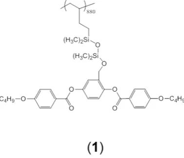
The side-on homopolymer (1), has a laterally attached butoxy benzoate side group (Figure 2.7), attached to 1,2 polybutadiene via silane coupling as described by Rafael Verduzco [13] [14]. The first batch of Polymer1used in these experiments was synthesized by Rafael Verduzco, I prepared later batches and all other polymers.
Figure 2.6. The structure of the side-on polymer, Polymer1.
2.3.3.1 Synthesis of Aldehyde-Containing Butoxybenzoate Mesogen for Siloxane Coupling
this green tinted solution, the crude butoxy-benzyl chloride was added, whereupon the mixture turned opaque yellow (Scheme 2.1). Dry argon gas was blown over the top of the mixture for five minutes, and the flask was then capped with a Teflon septum and reacted overnight at room temperature, yielding a dark purple reaction mixture.
The reaction mixture was poured onto 1N HCl to remove the pyridine. The organic layer was re-served and dicloromethane was used to extract any product dissolved in the HCl phase. This liquid-liquid extraction dichloromethane was repeated three times, followed by washing with a saturated NaHCO3solution three times. The combined organic layers were evaporated, and the product,
3,5-di(4-butoxybenzoate)-benzaldehde, was purified by recrystallization from hot ethanol into slightly pinkish crystals (12.28 g, 98.4% yield).
2.3.3.2 Siloxane Coupling and 1,2 Polybutadiene Functionalization of Aldehyde-Containing Bu-toxybenzoate
Scheme 2.1. The synthesis of the 3,5-di(4-butoxybenoate)-benzaldehde side group, “BB.”
The siloxane-linked mesogen was then attached to the pendant vinyl groups of 1,2-polybutadiene via platinum catalyzed hydrosilation (Scheme 2.2). Polybutadiene (0.0352 g, 0.6 mmols) was dissolved in 10 mL of anhydrous tetrahydrofuran (THF) under inert atmosphere. A three-fold excess of freshly purified SiBB and one drop of platinum catalyst (PC085, platinum cyclovinyl complex in vinylmethyl-siloxanes) were added, and the mixture was heated at 50◦C for four to six days. Reaction progress was monitored by1H NMR. When the reaction was complete it was quenched with excess styrene (about 3 Pasteur pipettefuls,∼4.5 mL) and heated at 50◦C overnight. The polymer was then purified by evap-orating all but the last 5 mL of solvent under vacuum, followed by repeated precipitation (sometimes up to 5 times) from THF solutions with cold methanol containing 10 ppm BHT (Butylated hydroxy-toluene or 2,6-di-tert-butyl-4-methylphenol), followed by drying to constant weight under vacuum at room temperature.
2.3.4 Synthesis of End-on SGLCP Homopolymers
2.3.4.1 Synthesis of Vinyl-Terminated Phenyl Pyrimidines for Siloxane Coupling
Vinyl-teminated phenyl pyrimidines with different spacer lengths were synthesized from 4-(5-decylpyrimidin-2-yl)phenol for siloxane coupling to 1,2 polybutadiene. A general procedure for this synthesis is as follows: 4-(5-decylpyrimidin-2-yl)phenol (1.89 g, 6.05 mmols), a bromoalkene (7-bromo hept-1-ene, 8-bromooct-1-ene or 10-bromododec-1-ene, 8mmol) and Cs2CO3 (2.56 g, 8 mmols) were stirred at
room temperature in 40 mL of dimethyl formamide overnight, resulting in near-quantitative conversion to the ether (Scheme 2.3), monitored by thin-layer chromatography. The reaction mixture was extracted three times with 50 mL of dichloromethane. The combined organic extracts were washed three times with water and dried with MgSO4. The crude product was recrystallized in hot 95% ethanol, resulting in
analytically pure white crystals of 5-decyl-2-(4-(hept-6-enyloxy)phenyl)pyrimidine, 5-decyl-2-(4-(oct-7-enyloxy)phenyl)pyrimidine, or 5-decyl-2-(4-(dec-9-enyloxy)phenyl)pyrimidine (1.20 g, 2.09 g, 1.69 g and 48.0%, 83.6%, or 66.02% overall yield, respectively).
Scheme 2.3. Williamson ether synthesis of end-on phenyl pyrimdine mesogenic side groups.
2.3.4.2 Siloxane coupling and 1,2 Polybutadiene Functionalization of Vinyl-Terminated Phenyl Pyrimidines
vinyl-terminated mesogens: A tenfold excess of 1,1,3,3-tetramethyldisiloxane (TMDS) (3 mL, 17 mmol) and the mesogens, e.g., C8PPC10V (0.693 g, 1.69 mmol) were dissolved in 20 mL anhydrous toluene. A drop of platinum catalyst (PC072 platinum divinyl complex in xylene) was added and the mix-ture was stirred at 50◦C for 2 days. This reaction was monitored by thin layer chromatography, and, when completed, the solvent and excess TMDS are evaporated at 80◦C under vacuum and the product (“SiC8PPC10”) was purified by anhydrous column chromatography (0.639 g, 69.1% yield).
Scheme 2.4. Siloxane coupling, first to vinyl-terminated mesogen, then to 1,2-polybutadiene.
methanol containing 10 ppm BHT, followed by drying to constant weight under vacuum at room tem-perature.
2.3.5 Synthesis of Benzoyl-Protected Thiols, for Thiol-Ene Coupling
Benzoyl-protected thiols were synthesized from 4-(5-decylpyrimidin-2-yl)phenol for thiol-ene coupling to 1,2 polybutadiene. 4-(5-decylpyrimidin-2-yl)phenol (1.89 g, 6.05 mmols), 1-bromo-6-chloro-hexane (1.57 g, 8 mmol) and CsCO3 (2.56 g, 8 mmols) were stirred at room temperature in 40 mL of dimethyl
formamide overnight, resulting in near-quantitative conversion of the ether (Scheme 2.5). The reac-tion mixture was extracted three times with 50 mL of dichlormethane. The organic extracts were washed three times with water and dried with Mg2SO4. The crude product was recrystallized in hot
95% ethanol, resulting in analytically pure white crystals (1.92 g; 76.56% overall yield) of 2(4-(5-chlorohexyloxy)phenyl)-5-decylpyridine.
Scheme 2.5. The synthesis of the protected thiol mesogenic phenyl pyrimidine side group.
2.3.5.1 Thioester cleavage and 1,2-Polybutadiene Functionalization.
(0.13 g, 1.9 mmol) and sodium acetate (0.13 g 1.9 mmol). The reaction mixture was purged with argon for 10 minutes and stirred for 6 hours at room temperature. The thiol product was extracted into 30mL of chloroform, washed 3 times with water and transferred into a flask containing 1,2-polybutadiene (0.03 g, 0.6 mmol) and AIBN (50 mg, 0.30 mmol) dissolved in 10 mL of chloroform. This mixture was then degassed in 2 freeze-pump-thaw cycles and then allowed to react at 55◦C overnight. The final polymer product (4) was then purified by evaporating all but the last 5mL of solvent under vacuum, followed by repeated precipitation from THF solutions with cold methanol containing 10 ppm BHT, then drying to constant weight under vacuum at room temperature.
Scheme 2.6. Thioester cleavage into thiol, followed by direct radical-catalyzed thiol-ene coupling with 1,2-polybutadiene.
2.3.5.2 Polymer Characterization
Proton nuclear magnetic resonance spectroscopy (1H NMR). 1H spectra (16 or 32 scans) of solu-tions of polymer (with concentrasolu-tions of approximately 10 to 20 mg/mL) in CDCl3 were recorded at
Gel permeation chromatography (GPC). The side group liquid crystal polymers relative molecu-lar weight and molecumolecu-lar weight distributions (PDI = Mw/Mn), were measured using gel permeation chromatography (GPC) calibrated with monodisperse PS standards.
2-7 mg polymer was dissolved∼1 mL of tetrahydrofuran (THF) and shaken for at least 30 min with a mechanical shaker. These solutions were filtered with a 0.45µm syringe filter prior to being injected into the GPC. The total time to traverse all four columns was approximately 45 minutes.
Polymer-FLC solutions. Polymers were dissolved in FLC hosts prepared by our collaborator, Michael Wand, at LC Vision in Boulder, CO.
2.3.5.3 FLC Hosts
The proprietary hosts (FLC-A, FLC-B, FLC-C, Table 2.1) provided by LC Vision are eutectic mix-tures of approximately 10 components, including mesogens (generally with phenylpyrimidine cores) and chiral dopants. Each mixture was characterized by broad SmC* temperature ranges accessible isotropization temperature and narrow windows of SmA and nematic phases, weak-to-moderate spon-taneous polarization (∼20 nC/cm2), and differing significantly in helical pitch and rise time.
Table 2.1. Three FLC hosts were designed by LC Vision to have polarization around∼20nC/cm2, and similar viscosity and dielectric constants, but varying in pitch.
2.3.5.4 Solutions of Polymers in FLC Hosts
Known weights of SGLCPS were dissolved in known weights of FLC host materials by repeated iterated heating to the isotropic phase followed by