Data Handling in the ALICE O
2Event Processing
MatthiasRichter1,2,∗,MikolajKrzewicki3, andGiulioEulisse1
1CERN, Route de Meyrin, 1211 Geneva, Switzerland
2University of Oslo, Department of Physics, Postboks 1048 Blindern, 0316 Oslo, Norway
3Frankfurt Institute for Advances Studies, Johann Wolfgang Goethe-Universität Frankfurt,
Ruth-Moufang-Straße 1, 60483 Frankfurt, Germany
Abstract. The ALICE experiment at the Large Hadron Collider (LHC) at CERN is planned to be operated in a continuous data-taking mode in Run 3. This will allow to inspect data from all Pb-Pb collisions at a rate of 50 kHz, giving access to rare physics signals embedded in a large background. Based on experience with real-time reconstruction of particle trajectories and
event properties in the ALICE High Level Trigger, the ALICE O2 facility is
currently designed and developed to support processing of a continuous, trigger-less stream of data segmented into entities referred to as timeframes.
Both raw data input into the ALICE O2 system and the actual processing of
aggregated timeframes are distributed among multiple processes on a many-node cluster. Process communication is based on the asynchronous message passing paradigm.
This paper presents the basic concept for identification of data in the distributed system together with prototype implementations and performance measure-ments.
1 Introduction
For the LHC Run 3 period, a new detector readout concept will be applied for the ALICE experiment [1] at CERN. As a primary goal, the inspection of all collisions delivered by the accelerator is planned, which will take place at a rate of 50 kHz for Pb-Pb collisions. This requires to operate some of the detectors in a continuous readout mode which will increase data rate significantly. The total data rate delivered by the different detectors of the ALICE experiment will be about 3 TByte/s. In order to cope with the large amount of data, the ALICE O2 collaboration is currently developing a combined online-offline data processing
system [2], with O2indicating the joint online-offline effort.
As a consequence of the continuous readout scheme, a time based data organization has been introduced in ALICE O2. For data processing, the traditional entity of an event, i.e. one
triggered collision, has been replaced by a so-called timeframe which is a container for data delivered within a period of time. These data include both data delivered by the detectors as well as temporary and permanent results of the processing and reconstruction.
Individual compute tasks will be carried out concurrently by individual processes. The computing resources to run several thousands of these processes are provided by the ALICE O2Online Cluster of about 1800 compute nodes.
The message passing paradigm is applied for synchronization and communication be-tween processes. A flexible and appropriate implementation is provided by the FairMQ package of the ALFA software framework [3].
After aggregation of all data forming a timeframe in the event processing stage, algo-rithms need to efficiently navigate through large data sets and have to be able to add new data to the data stream. Both data format and software framework have been designed and implemented with emphasis on lightweight data organization and optimized in-memory data format, supporting an efficient pipelined data processing.
This paper introduces online data processing for ALICE in LHC Run 3 in Section2and outlines the requirements for the data organization. The implementation is presented and discussed in Section3. Section4summarizes the conclusions of the paper.
2 Online Data Processing in ALICE Run 3
2.1 OverviewAs already mentioned, the ALICE O2 facility combines the traditional online and offline domains in a common data processing system. The data flow is illustrated in Figure1.
The ALICE O2 Online Cluster consists of two types of compute nodes, the so called First Level Processors (FLP) and the Event Processing Nodes (EPN). Data from the different detectors are received by the dedicated FLP nodes, which host the Common Readout Unit (CRU) as the hardware interface to the detector frontend. The CRU has access to the memory of the FLP to write data via Direct Memory Access (DMA) transactions, a feature which allows access to the main system memory independently of the central processing unit. In total there will be 270 FLP nodes in the O2Online Cluster. At the level of the FLP there is a data rate reduction from 3.4 TByte/s to 500 GByte/s achieved by partial reconstruction of the data on hardware co-processors and using appropriate data formats and compression for transmitting the data. All data on the FLP, i.e. raw data and the result of local synchronous processing tasks, are organized in sub-timeframes.
Figure 1.A logical view of the O2online data flow.
The Data Distribution Service running on FLPs and EPNs is responsible for the transport of sub-timeframes from FLPs to EPNs. A 500 GByte/s switching network comprises the hardware backbone of the data distribution [4].
The 1500 Event Processing Nodes of the O2facility provide the computational resources for data reconstruction in ALICE O2. Complete timeframes are aggregated on single EPNs for the first pass of reconstruction, referred to as synchronous reconstruction. The syn-chronous reconstruction includes a variety of tasks depending on the detector, like cluster-ization and tracking for individual detectors, global matching of track data, calibration tasks and final data compression algorithms. Such sets of algorithms are applied to the incoming data set and new intermediate data are produced and added to each timeframe.
At the end of the synchronous reconstruction, timeframe data are written in compressed format, theCompressed Timeframe, to disk in the persistent on-site storage. Until this point,
all data are only in the memory of the compute nodes. The asynchronous reconstruction pass will at a later time produce the physics-ready data on the basis of the compressed timeframe data and additional condition data like e.g. updated calibration.
2.2 Requirements and Tasks for Data Handling
ALICE O2defines a streaming model for the data transport. All data are wrapped into mes-sages. The FairMQ package [5] of the ALFA project, a common software project between FAIR and ALICE, is used as the underlying transport layer. FairMQ implements an abstrac-tion layer to the basic message passing funcabstrac-tionality via channels, leaving it to the applicaabstrac-tion to add a protocol or data model on top of the basic communication. The package supports a variety of messaging solutions like e.g. ZeroMQ for inter-node communication at the same time as shared memory for intra-node communication. FairMQ implements the asynchronous message passing paradigm which allows the different processes to run independently from each other.
ALICE O2serves several independent tasks like raw data processing, detector reconstruc-tion, quality control, and data analysis. Raw data comes from different detector systems, each of them requiring specific reconstruction algorithms. Furthermore, each of the tasks might also produce intermediate data sets. It’s difficult to describe all data in advance. As the sys-tem is under development in an agile manner, new data structures will emerge and the O2 facility has to deal with many kinds of data.
Considered all these different use cases and requirements, the aim is to define a flexible scheme to describe a set of data as a container with unique identification of data and capability to efficiently navigate within the container. In particular, a timeframe can be defined in such a scheme as a container for data within a certain period of time.
An essential part of such a description isdata annotationas a prerequisite to uniquely identify data parts. The data annotation scheme has to fulfill the following requirements:
• Coherent annotation for all types of data
• Support aggregation of data
• Raw data annotation without copying or parsing
• Allow for accumulation of data
• Support for addons to the annotation
• Provide timing information
• Support for simple scatter/gather I/O
In the following section we introduce an implementation currently used in ALICE O2to support these requirements.
3 Implementation
3.1 The Data Model for Transport
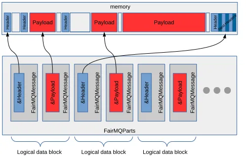
As already mentioned, the individual processes carrying out the various tasks in the O2 sys-tem exchange data via messages. For our data model we define anO2Messageobject as a collection of annotated data payloads in logical blocks, see Figure2. Each logical block
Currently, the data model is using the ability of grouping messages by the transport. TheFairMQPartscontainer is used to build up theO2Messagefrom individual messages. However, this is not a restriction to a specific implementation, but can simply be seen as a tool for maintaining a sequence of messages. FairMQMessageandFairMQPartsare primitives of theFairMQpackage.
Payload H e a d e r Next Hea ders
Logical data block
Payload H e a d e r H e a d e r H e a d e r Payload memory FairMQParts F a ir M Q M e s s a g e & H e a d e r F a ir M Q M e s s a g e & P a y lo a d F a ir M Q M e s s a g e & H e a d e r F a ir M Q M e s s a g e & P a y lo a d F a ir M Q M e s s a g e & H e a d e r F a ir M Q M e s s a g e & P a y lo a d
Logical data block Logical data block
Figure 2.The O2data model defines theO2Messageas a sequence ofheader-payloadpairs. The actual
place in memory where individual messages are stored is independent from the sequence maintained in
the container. Headers can be singleDataHeaderobjects as well as a stack of multiple headers.
In this model, all information necessary for the routing is stored in the header message. In order to fulfill the requirement of flexibility, the header message is composed of a variable number of headers in astack.
3.2 Data Annotation
The main task of the data annotation is to provide a descriptive information uniquely iden-tifying a piece of data in the stream. It also has to ensure navigation within data sets. The annotation has to take account of the fact that most of the data have a time context, but some do not, some are temporary, and some are intended for storage.
By separating the header message from the payload message, data can be sent from the initial hardware device without the need for copying or moving data. This takes account of the fact that the FLP memory region for receiving the readout data from the CRU is entirely reserved for this kind of communication. There are no reserved regions where annotations could be inserted, nor would a variable-length annotation be easy to implement.
By policy, each header message starts with the DataHeaderwhich identifies all types of data in a unified way. This header contains the general identifying properties, like origin of data and a descriptive ID for the type. A further sub-specification allows to identify data of the same origin and description but e.g. originating from different geometrical regions. Figure3shows a memory dump of aDataHeaderobject.
Currently, the data model is using the ability of grouping messages by the transport. TheFairMQPartscontainer is used to build up theO2Messagefrom individual messages. However, this is not a restriction to a specific implementation, but can simply be seen as a tool for maintaining a sequence of messages. FairMQMessageandFairMQPartsare primitives of theFairMQpackage.
Payload H e a d e r Next Hea ders
Logical data block
Payload H e a d e r H e a d e r H e a d e r Payload memory FairMQParts F a ir M Q M e s s a g e & H e a d e r F a ir M Q M e s s a g e & P a y lo a d F a ir M Q M e s s a g e & H e a d e r F a ir M Q M e s s a g e & P a y lo a d F a ir M Q M e s s a g e & H e a d e r F a ir M Q M e s s a g e & P a y lo a d
Logical data block Logical data block
Figure 2.The O2data model defines theO2Messageas a sequence ofheader-payloadpairs. The actual
place in memory where individual messages are stored is independent from the sequence maintained in
the container. Headers can be singleDataHeaderobjects as well as a stack of multiple headers.
In this model, all information necessary for the routing is stored in the header message. In order to fulfill the requirement of flexibility, the header message is composed of a variable number of headers in astack.
3.2 Data Annotation
The main task of the data annotation is to provide a descriptive information uniquely iden-tifying a piece of data in the stream. It also has to ensure navigation within data sets. The annotation has to take account of the fact that most of the data have a time context, but some do not, some are temporary, and some are intended for storage.
By separating the header message from the payload message, data can be sent from the initial hardware device without the need for copying or moving data. This takes account of the fact that the FLP memory region for receiving the readout data from the CRU is entirely reserved for this kind of communication. There are no reserved regions where annotations could be inserted, nor would a variable-length annotation be easy to implement.
By policy, each header message starts with theDataHeader which identifies all types of data in a unified way. This header contains the general identifying properties, like origin of data and a descriptive ID for the type. A further sub-specification allows to identify data of the same origin and description but e.g. originating from different geometrical regions. Figure3shows a memory dump of aDataHeaderobject.
All identifiers are integral numbers of a fixed width. The values of the specific IDs are built at compile time from strings making a memory dump readable at the same time as integral numbers can be used for comparison of values.
0x41c8b270 4f 32 4f 32 50 00 00 00 00 00 00 00 01 00 00 00 O2O2P... 0x41c8b280 44 61 74 61 48 65 61 64 4e 4f 4e 45 00 00 00 00 DataHeadNONE.... 0x41c8b290 43 4c 55 53 54 45 52 00 00 00 00 00 00 00 00 00 CLUSTER... 0x41c8b2a0 54 50 43 00 ff ff ff ff 4e 4f 4e 45 00 00 00 00 TPC...NONE.... 0x41c8b2b0 2a 00 00 00 00 00 00 00 00 04 00 00 00 00 00 00 *...
Figure 3.Example for a memory dump of aDataHeaderobject. It identifies the type of data byorigin, data description, and asub-specification. The integral IDs are build from strings at compile time. This
allows for an easy recognition of patterns in memory. Here we see the general O2 header identifier
O2O2, the header idDataHead, the data originTPCand descriptionCLUSTER. Both header and payload
messages are not serialized indicated by the serialization IDNONE.
3.3 Header Stack
Flexibility has been an important requirement for the design of the data annotation. In order to take into account the different needs of the individual detector systems, data annotations have to be flexible in size and content. They also can be extended over the lifetime of the project. Examples are origin-specific or trigger-specific headers.
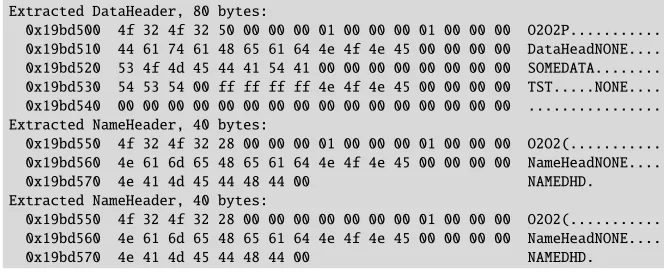
For this particular reason, theHeader Stackconcept has been introduced which allows to extend the header message. A stack is composed from an arbitrary sequence of headers.
HeaderStack stack{h1, h2, h3, ...};
It has to be noted that the composition of a stack happens directly in the allocated memory, thus avoiding additional copy operations. The implementation comes with tools to iterate and extract individual headers. Figure4shows a memory dump of a header stack.
Extracted DataHeader, 80 bytes:
0x19bd500 4f 32 4f 32 50 00 00 00 01 00 00 00 01 00 00 00 O2O2P... 0x19bd510 44 61 74 61 48 65 61 64 4e 4f 4e 45 00 00 00 00 DataHeadNONE.... 0x19bd520 53 4f 4d 45 44 41 54 41 00 00 00 00 00 00 00 00 SOMEDATA... 0x19bd530 54 53 54 00 ff ff ff ff 4e 4f 4e 45 00 00 00 00 TST...NONE.... 0x19bd540 00 00 00 00 00 00 00 00 00 00 00 00 00 00 00 00 ... Extracted NameHeader, 40 bytes:
0x19bd550 4f 32 4f 32 28 00 00 00 01 00 00 00 01 00 00 00 O2O2(... 0x19bd560 4e 61 6d 65 48 65 61 64 4e 4f 4e 45 00 00 00 00 NameHeadNONE.... 0x19bd570 4e 41 4d 45 44 48 44 00 NAMEDHD. Extracted NameHeader, 40 bytes:
0x19bd550 4f 32 4f 32 28 00 00 00 00 00 00 00 01 00 00 00 O2O2(... 0x19bd560 4e 61 6d 65 48 65 61 64 4e 4f 4e 45 00 00 00 00 NameHeadNONE.... 0x19bd570 4e 41 4d 45 44 48 44 00 NAMEDHD.
Figure 4.Example of a header stack memory dump. In this example the header message consists of 3 individual headers.
3.4 Applying Processing Pipelines - The Data Processing Layer
The ALICE O2Data Processing Layer (DPL) is a framework providing declarative workflow
definition to establish data processing pipelines. It is an integral part of the ALICE Software Framework for LHC Run 3 and beyond ([6]).
• Definition of processors in terms of inputs, outputs and algorithm
• Based on the input and output definitions, processors are connected in a workflow • Deployment of workflow on computing resource using a control tool
The DPL uses the data annotation scheme to describe input and output specifications as well as to identify routing of data. This abstraction of a computation described by input, output and algorithm specifications introduces a great flexibility in ALICE O2and, moreover,
the ability to handle complex workflows efficiently.
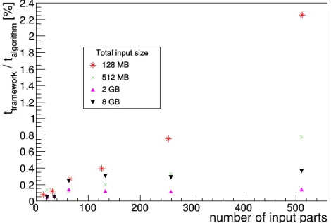
As flexibility comes at a cost, the impact of the framework data handling on the total processing time has been assessed. A simple, yet realistic model which uses an example process with a very generic and fast algorithm has been evaluated. The TPC hardware cluster decoder is a good candidate, as it is a simple data parsing algorithm with the purpose of decoding and reformatting data. The data object holding the information of a reconstructed space point in the TPC is referred to as a TPC cluster. Naturally, the processing time depends on the input size, i.e. the number of cluster objects in the data set. Furthermore, the input data set can be split into several parts, making each part a subset of the total data set. This follows the FLP-EPN setup in ALICE O2. The number of FLPs, 270 in the current design, describes
the order of magnitude for the number of parts a data set can be split into. The result of the tests are shown in detail in Figure5. We summarize that less than 2% are consumed by framework functionality for a very simple algorithm. It can thus be concluded that the impact is negligible for more complex algorithms.
Figure 5.Processing time spent in the framework functionality relative to the total processing time of the TPC hardware cluster decoder as an example for a simple and fast algorithm.
3.5 Raw Data access
Some important aspects of the ALICE O2 readout are briefly introduced in the following.
• Definition of processors in terms of inputs, outputs and algorithm
• Based on the input and output definitions, processors are connected in a workflow
• Deployment of workflow on computing resource using a control tool
The DPL uses the data annotation scheme to describe input and output specifications as well as to identify routing of data. This abstraction of a computation described by input, output and algorithm specifications introduces a great flexibility in ALICE O2and, moreover, the ability to handle complex workflows efficiently.
As flexibility comes at a cost, the impact of the framework data handling on the total processing time has been assessed. A simple, yet realistic model which uses an example process with a very generic and fast algorithm has been evaluated. The TPC hardware cluster decoder is a good candidate, as it is a simple data parsing algorithm with the purpose of decoding and reformatting data. The data object holding the information of a reconstructed space point in the TPC is referred to as a TPC cluster. Naturally, the processing time depends on the input size, i.e. the number of cluster objects in the data set. Furthermore, the input data set can be split into several parts, making each part a subset of the total data set. This follows the FLP-EPN setup in ALICE O2. The number of FLPs, 270 in the current design, describes the order of magnitude for the number of parts a data set can be split into. The result of the tests are shown in detail in Figure5. We summarize that less than 2% are consumed by framework functionality for a very simple algorithm. It can thus be concluded that the impact is negligible for more complex algorithms.
Figure 5.Processing time spent in the framework functionality relative to the total processing time of the TPC hardware cluster decoder as an example for a simple and fast algorithm.
3.5 Raw Data access
Some important aspects of the ALICE O2 readout are briefly introduced in the following. Details on this topic can be found in [7]. Data are written by the hardware input device in
raw page formatinto the FLP shared memory. The shared memory section is allocated by the specific readout process and provided to the driver. Raw pages have a fixed size of currently 8 kByte. Each raw page starts with theRawDataHeader (RDH).
In many cases the data will be in the form of discrete objects of the same data type, possibly grouped into blocks with a common data attribute. Because of the fixed size of raw pages and the mandatoryRawDataHeaderin the beginning of each page, a sequence of objects either stays within pages or wraps over to next page(s). This also depends on the sizes of attribute and object data type.
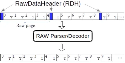
A generic RAW data parser/decoder, templated on aPageHeadertype andElementType
has been implemented to support data access for a large variety of detectors with a single simple implementation. Figure6illustrates the working principles of the decoder.
Figure 6. Schematic view of the access of data elements through generic raw decoder. The elements
of a typeTare sequentially stored in raw pages starting with theRawDataHeader. Elements can either
wrap over page boundaries or as many elements as possible are stored in each page, eventually adding padding to fill the page. In either case the data can be accessed in a sequential view using the raw decoder.
The decoder produces an iterable view on data elements and supports groups of data objects described by aGroupHeadertype. It also supports multiple non-contiguous pages. An example how to setup and use the decoder is given in the following code listing:
using PageHeaderType = o2::header::RAWDataHeader; // set up the decoder for some element type
RawParser<PageHeaderType, 8192, ElementType> RawParser; RawParser parser(ptr, size);
for (const auto& element : parser) { // do something with element }
4 Summary
complexity of processing topologies requires a higher-level multi-processing framework in order to scale the system from simple prototypes with a few parallel processes to a dynamic processing topology of thousands of processes on many-node compute clusters. The data model and data annotation have been proven to be important core functionality of such an implementation in ALICE O2.
References
[1] The ALICE Collaboration, JINSTVol 3,S08002(2008)
[2] The ALICE Collaboration, Technical Design Report for the Upgrade of the Online-Offline Computing System,CERN-LHCC-2015-006(2015)
[3] M. Al-Turany et al.,ALFA: ALICE-FAIR new message queuing based framework, Proceedings of 23rd Computing in High Energy Physics (2018), CHEP2018
[4] G. Neskovic,Data distribution and load balancing for the ALICE Online-Offline (O2)
system,Proceedings of 23rd Computing in High Energy Physics (2018), CHEP2018 [5] FairMQ,https://github.com/FairRootGroup/FairMQ