DOI : https://doi.org/10.32628/CSEIT1952184
Harmonic Analyzer Using ATMEGA 328P
Christie Anil Joseph*1, Sumant Sarmokadam2, Dr. Usha Surendra31,.3 Electrical and Electronics Engineering Department, Christ( Deemed to be University), Bengaluru, Karnataka,
India
2Electrical Engineering Department, St.Vincent Pallotti College of Engineering and Technology, Nagpur,
Maharashtra, India
ABSTRACT
The technical improvement in Power electronics and Control system industries has made the linear consumer loads to dominate by sensitive and sophisticated non-linear consumer loads. These have a major impact on the power systems, causing increase in harmonics distortion. This paper proposes a hardware design to develop a Harmonic Analyzer along with Arduino ATMEGA 328P, that can be able to analyze up to 15th harmonic of an alternating current power supply. The Harmonic analyzer has been developed considering the cost, accomplished with respect to accuracy, easy modifications through coding, remote monitoring and data logging. The developed low cost handheld product may be used for industrial as well as commercial applications.
Keywords: Power Quality, Harmonics, Total Harmonic Distortion (THD), Current Harmonics, Industrial System, Semiconductor Devices.
I. INTRODUCTION
The idea of the electrical power is one of the basic parameters that hamper to convey the stable power. The quality of power is affected by the continuity of the service, Voltage and Current parameters and Harmonics contents in the Ac power Waveform. A pure Power quality has an unadulterated, commotion free sinusoidal wave-shape, and is dependably inside voltage and frequency tolerance i.e inside the range.
In ideal world, the non-linear loads associated with the distribution network draw a non-sinusoidal flow that is current. This non-sinusoidal current travels through the system impedance and produces voltage drop which reshape the sinusoidal supply voltage. These distorted voltage and currents are called harmonics. In this paper analog signal is taken from
the power line which is in current and voltage form by using Current Transformer (CT) and Potential Transformer (PT). The analog signal sampled and converted into digital form by using Analog to Digital Converter which is inbuilt in microcontroller. Microcontroller is programmed in such a way to get Fast Fourier Transformation of the sampled Signals. A graphical display is interfaced with the microcontroller which will display the harmonics present in the power line. The cost of this harmonics analyzer is less, which analyses harmonics up to 15th order.
II. METHODS AND MATERIAL
The non-linear loads associated with the distribution network draw non-sinusoidal flows that is current. This non-sinusoidal current travels through the system impedance and produces voltage drop which reshape the sinusoidal supply voltage These distorted voltage and currents are called harmonics. This is indicated in Fig.1.
Characteristic Equation of Harmonic current:
Power change using full wave rectifiers creates idealized characteristic harmonic currents given by:
h = x. p ± 1 (1)
Where, h=order of harmonics
Fig. 1 Harmonics x=an integer 1, 2, 3…
p=number of current pulses per cycle
Calculation of Voltage Distortion :
The instantaneous value of voltage for non-sinusoidal waveform or complex wave can be expressed as:
= V0 + V1sin(ωt + φ1) + V2sin(2ωt + φ2)
+... Vn sin(nωt + φn) (2)
Where, V = instantaneous value at any time t V0 = direct (or mean) value (DC component) V1 = rms value of the fundamental component V2 = rms value of the second harmonic component Vn = rms value of the nth harmonic component
B. SOURCES OF HARMONICS:
The root cause of harmonics [3] may be classified as follows.
• Arcing devices.
• Electronic power supply system. • Power drives.
• Thyristor controlled reactors • Phase controllers
• A.C. regulators
C. PROBLEM ASSOCIATED WITH HARMONICS
INTERFACE:
Issues related with the harmonic interface [1] are as per the following:
1. Transformer losses increase. 2. False stumbling of circuit breakers. 3. Shortening of life of electrical insulation. 4. Damaging of electrical circuits.
5. Sometimes, Harmonics will introduce wrong meter readings during normal condition
6. The presence of power factor equipment will result in the system resonance that leads to higher value of voltage and current, is a considerable parameter for the system.
D. PROPOSED METHOD
using program in embedded C for finding Fourier transform of time domain signal . This frequency domain signal from Arduino will be given as input to LCD graphical display. By observing the graphs on LCD graphical display we can analyze harmonics of power signal.
Fig. 2 Block diagram
Fig. 3 Flowchart
Fig. 4 Harmonics analyzer circuit using Arduino ATMEGA 328P
The step by step analysis of the harmonics for the given circuit (fig 4) has been indicated in the flowchart (fig 3). In this paper the effects and the problems that arise in the power system due to harmonics distortion are also explained.
A) Hardware Circuitry:
Hardware developments include circuit design of ADC section, Micro-controller section, power supply circuit and component mounting and testing.
B) Software system:
Software coding is done in embedded C language. Arduino ATMEGA 328P is used. This coding is done for Micro-controller to perform following functions:
1. To read the parameters measured by ADC. 2. Conversion of coded register values to real world
values.
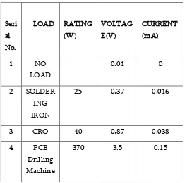
Seri
III. RESULTS AND DISCUSSION
The Harmonic analyzer is developed considering the parameters like versatility with respect to accuracy, cost and applicability, ease of modifications through coding, remote monitoring and data logging.
The signals are taken from the power line by using current transformers and voltage transformers and given to the microcontroller. The microcontroller first samples the data by using inbuilt A/D converter and then it analyzes the sampled data. After analyzing the data, output is observed on the graphical display board interfaced with the microcontroller.
The plot of the real time graph of the harmonics as well as the real time readings can be carried out by connecting a switch i.e one terminal to 5V supply and other terminal to the input of the Arduino.
Fig 6. Real time graph
When the switch is closed, it will show the normal readings and when the switch gets opened, real time graph can be observed.
IV.CONCLUSION
In this paper, the sources of harmonics and its effects on the power system were discussed. A low cost harmonic analyzer can be designed using Arduino ATMEGA 328P. The Harmonic analyzer kit can analyze harmonics upto the load of 500W, the range can be used to several KW using a potential divider circuit. Also, based on the readings, filters can be used to minimize the harmonics.
The hardware design suggested that harmonics can be analyzed up to 15th harmonic of a A.C. power supply. Also, real time readings and graph can be plotted.
V. REFERENCES
[1] Srijan Saha, Champa Nandi, ―Modelling and
Harmonic Analysis of Domestic/Industrial Loads,‖
[2] Design And Development of Smart Harmonic Analyzer‖ shodhganaga.inflibnet.ac.in
[3] IEEMA Journal, June 2017
[4] Electrical India Magazine, August 2016.
APPENDIX
1. Current Transformer:
a)Nominal Input Current : 20 A b)Output Current : 8 mA c)Operating Frequency : 50Hz d) Accuracy: 0.1%
e) Winding Ratio 2500:1
2. Instrument Transformer:
a) Nominal High Voltage: 230 V
b) Output Voltage: 6 V
3. Micro-controller: ATmega328P-PU
a) Operating Voltage -5V
b) Digital Input- Output pins -14
c) Analog Input Pins - 6
d) DC current per Input -Output pin - 40 mA
e) Flash memory - 32 KB
f) SRAM - 2KB
g) Clock speed - 16MHz
Cite this article as :