Implementation of Multi level Inverter Topology with Reduced Switches
for Grid Interconnection of PV Systems
A.Naresh & Ch.Sridhar
1M-tech Student Scholar Department of Electrical & Electronics Engineering, Bapatla Engineering College, Bapatla; Guntur
(Dt); A.P, India.
2Assistant Professor Department of Electrical & Electronics Engineering, Bapatla Engineering College, Bapatla; Guntur (Dt);
A.P, India.
Abstract-This paper presents a multilevel inverter that has been conceptualized to reduce component count, particularly for a large number of output levels. It comprises floating input dc sources alternately connected in opposite polarities with one another through power switches. Each input dc level appears in the stepped load voltage either individually or in additive combinations with other input levels. This approach results in reduced number of power switches as compared to classical topologies. Renewable energy sources plays a key role in recent times as they are free from pollution, unlimited and reduces the cost related with its control. Among them Solar energy is more beneficial as the impact of solar systems on environment are significantly lower than non-solar system. Generally, solar cell is the device which converts solar energy into DC electricity. Usually we need a suitable converter for the purpose of conversion from DC to AC and then it is injected to power Grid. In this paper, the inverter action is carried out by using cascaded H-Bridge inverter with reduced number of switches. The proposed inverter is been used to integrate the solar system to Grid, taking into consideration of Grid requirements. In the absence of solar supply, we use Grid to feed the load. In the present work, a multilevel line commutated inverter topology has been proposed and analyzed which improves t he wave shape and hence reduces the total harmonic distortion (THD) of the line current in a grid tie line commutated inverter. The proposed Cascaded H-Bridge Inverter will be simulated using MATLAB/SIMULINK.
I. INTRODUCTION
Over the past few years, technological advances in power electronics and increasing demand for energy have contributed to rapid development of power generation based on renewable energy sources as like the Photovoltaic (PV), Wind and Fuel cell (FC) based renewable energy technologies [1-3]. One of the problems focused in the research is the constraint of power electronic switches. If the power electronic devices which can prolong high voltage are used in the inverter, their switching frequency is restricted. Hence, the device voltage must be reduced to use high-speed switching devices. A multilevel inverter can reduce the device voltage and the output harmonics by increasing the
number of output voltage levels. Further, increase in number of isolated DC sources in order to increase the number of output voltage levels leads to additional system complexity especially in PV and FC fed inverter topologies. In single-phase multi-level inverters, the most widely used techniques are cascaded H-bridge (CHB), diode-clamped and capacitor-clamped types [7-9]. This paper proposes a latest MLI which is used to convert DC to AC using reduced number of switches, when compared to conventional MLI. By this less number of switches, switching losses can be avoided [4-5].
Basically Inverter is a device that converts DC power to AC power at desired output voltage and frequency. Demerits of inverter are less efficiency, high cost, and high switching losses. To overcome these demerits, we are going to multilevel inverter. The term Multilevel began with the three-level converter. The concept of multilevel converters has been introduced since 1975 [6]. The cascade multilevel inverter was first proposed in 1975. In recent years multi level inverters are used high power and high voltage applications. Multilevel inverter output voltage produce a staircase output waveform, this waveform look like a sinusoidal waveform. The multilevel inverter output voltage having less number of harmonics compare to the conventional bipolar inverter output voltage. If the multilevel inverter output increase to N level, the harmonics reduced to the output voltage value to zero. The multi level inverters are mainly classified as Diode clamped, Flying capacitor inverter and cascaded multi level inverter. The cascaded multilevel control method is very easy when compare to other multilevel inverter because it doesn’t require any clamping diode and flying capacitor [7-9].There are two PWM methods mainly used in multilevel inverter control strategy.
series/parallel conversion of DC sources. In the proposed Multilevel Inverter three similar Cascaded H-Bridges are used, each Bridge carries an auxiliary switch which will be Bidirectional in nature. The proposed multilevel inverter topology can be extended for the application of grid connected photo voltaic systems, hybrid electric vehicles, etc. Furthermore, theoretical analysis, numerical simulations and experimental results are also presented to demonstrate the validity of the proposed single phase cascaded multilevel inverter.
II. MULTILEVEL INVERTER
The general structure of proposed new multilevel inverter is shown in the fig.1. It consists of a one H-bridge inverter and 'N' number of cascaded cells, which are having a dc rating of V dc. The number of levels can be given by the formula:
(1) Where n= Number of cells excluding the H-bridge. For generating + V dc we need turned on switches S I and S2, for -V dc, switches S3 and S4 has to be turned on, and for zero voltage either switches Sl and S3 or switches S2 and S4 has to be turned on.
Fig.1 General Structure of proposed new multilevel inverter
has 7 levels: ± 3Vdc, ± 2Vdc, ± Vdc and 0. Circuit diagram of proposed seven level multilevel inverter is shown in fig.2.
Fig.2. Circuit diagram of seven level proposed inverter
For generating seven levels, the proposed inverter uses two cells that mean it contains two switches and two diodes in addition with the one H-bridge. The output voltage waveform of the ideal seven level inverter is shown in fig .3.
B. Thirteen Level Proposed Multi level inverter
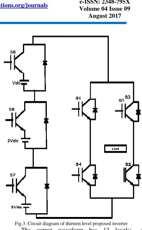
The thirteen level proposed inverter uses only seven switches compared to cascaded H-bridge inverter which uses twenty four switches and six separate dc sources. But in proposed inverter, the requirement of separate dc sources is only three and the switching losses are also low. Using proper switching sequence proposed circuit generates seven levels in output voltage. Table 2 shows the switching sequence used for creating thirteen levels for the output voltage.
Table 2: Switching Sequence for Proposed Thirteen Level Inverter
Circuit diagram of proposed thirteen level multilevel inverter is shown in fig.4
Fig.3. Circuit diagram of thirteen level proposed inverter
Fig.4.Circuit diagram of 21 levels proposed inverter
Table 3: Switching Sequence for Twenty One Level Inverter
Table 4: Comparisons between Different Topologies
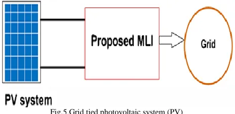
Fig.5.Grid tied photovoltaic system (PV)
From fig.5 the PV cell directly converters the solar energy into electricity in the form of dc [8]. The voltage obtained from the PV is converted into ac using the proposed inverter. Finally the proposed inverter is connected to the power grid with satisfying the grid requirements such as phase angle, frequency and amplitude of the grid voltage.
IV. MATLAB/SIMULINK RESULTS
Fig.7. Proposed seven level inverter output voltage
Fig.8 THD plot of 7-level inverter
Fig.9.Matlab/Simulink diagram of proposed seven level MLI with 6 switches
Fig.10. Proposed seven level inverter output voltage
Fig.11 THD plot of 7-level inverter with 6 switches
Fig.13. Proposed eleven level inverter output voltage
Fig.14 THD plot of 11-level inverter
Fig.15 Matlab/Simulink diagram of proposed 13 level inverter
Fig.17 THD plot of 13 level inverter
Fig.18 MATLAB/SIMULINK diagram of twenty one level without grid connected MLI.
Fig.19 Grid current and voltage
Fig.20 Power factor angle between voltage and current
Fig.21 Grid Connected PV system based on Multilevel Inverter with twenty one level with grid connected.
Fig.23 THD of the 21-level.
V. CONCLUSION
This paper has presents a novel single phase cascaded H-bridge Inverter with reduced number of power electronics devices and isolated DC sources. Simulations are carried out in MATLAB/Simulink. The performance of the suggested novel cascaded H-Bridge multilevel inverter is investigated in detail. The modulation waveform and the harmonic analysis are also presented for various values of modulation strategies. By properly adjusting the modulation index, the required number of levels of the inverter output voltage can be achieved. This proposed inverter system offers the advantage of reduced switching devices and isolated DC sources. A PV based modified MLI with reduced switches, integrated scheme for power grid is proposed in this paper. This topology eliminates the harmonics at the solar system by expanding and increasing the number of output levels with less number of switches, the initial cost is also reduced. Increasing the number of output voltage levels reduces the lower order harmonics and the THD. It's preferred that the output voltage has no lower order harmonics because their filtering is so hard. From the results grid voltage and grid connected current are in phase with each other.
REFERENCES
[1]. Prasadarao K. V.S, Sudha Rani.P, Tabita. G. “A new multi level inverter topology for grid interconnection of PV systems,” 2014 Power and Energy Systems: Towards Sustainable Energy (PESTSE 2014). [2]. S.K.Khadem, M. Basu and M.F. Conlon. “Power quality in Grid connected Renewable energy systems: Role of custom power devices,”
[6] F. Gao, D. Li, P. C. Loh, Y. Tang, and P. Wang, “Indirect dc-link voltage control of two-stage single-phase PV inverter,” in Proc. 2009 IEEE ECCE, 2009, pp. 1166–1172.
[7] A. Nami, F. Zare, A. Ghosh, and F. Blaabjerg, “A hybrid cascade converter topology with series connected symmetrical and asymmetrical diode clamped H-Bridge cells,” IEEE Trans. Power Electron.,vol. 26, no. 1, pp. 51–65, Jan. 2011.
[8] S. Dwari and L. Parsa, “An efficient high-step-up interleaved dc–dc converter with a common active clamp,” IEEE Trans. Power Electron., vol. 26, no. 1, pp. 66–78, Jan. 2011.
[9] J.-M. Shen, H.-L. Jou, and J.-C.Wu, “Novel transformerless grid connected power converter with negative grounding for photovoltaic generation system,” IEEE Trans. Power Electron., vol. 27, no. 4, pp. 1818–1829, Apr. 2012.
[10] T. Kitano, M. Matsui, and D. Xu, “Power sensorless MPPT control scheme utilizing power balance at DC link—System design to ensure stability and response,” in Proc. 27th Annu. Conf. IEEE Ind. Electron. Soc., 2001, vol. 2, pp. 1309–1314.