SIMULATION RESEARCH ON TURBO EQUALIZATION ALGORITHM BASED ON MICROWAVE FADING
CHANNEL
S. X. Guo, Y. Gao, and L. X. Zhang
UAV Specialty Technique Key Laboratory of National Defense Technology
Northwestern Polytechnic University Xi’an, Shaanxi 710072, China
Abstract—Turbo equalization is applied to microwave channel in this paper, and we bring forward an improved Turbo equalization algorithm named Max-Log-Map. A simulation based on a given microwave fading channel has been made. The results show that performances are close to each other between improved TE-Max-Log-Map and Log-Map, and the coding gain is 1 dB at 10−4 of BER compared with Max-Log-Map. The improved Max-Log-Map method improves the reliability of microwave communication.
1. INTRODUCTION
and the equalizer result will not be ideal. In recent years, iterative decoding method of Turbo code inspired Turbo equalization which combines Turbo code decoding principle with equalization technology. Turbo equalization improves largely the reliability of communication by many iterations of soft information between decoder and equalizer. The principle of Turbo equalization is applied in microwave communication in this paper. In view of ISI caused by microwave channel’s multipath fading, an improved Max-Log-Map equalization algorithm is brought forward and simulated in a given microwave channel. Simulation results show that the improved algorithm gets about 1 db coding gain compared with Max-Log-Map when BER is 10−4, which is close to Log-Map performances, so the improved algorithm improves the reliability effectively in microwave communication.
+−
+ −
k
Z
( )
pos E k
L x ext( )
E k
L x pri( )
D k L x
( )
pri E k
L x
k
u
( )
pos D k L u
( )
pos D k L x
( )
ext D k
L x' '
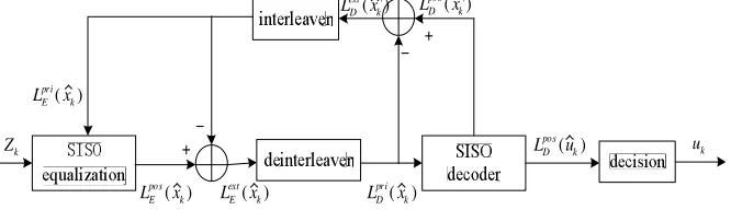
Figure 1. Turbo equalizer structure.
2. THE PRINCIPLE OF TURBO EQUALIZATION
Turbo equalization structure is shown in Figure 1, it needs multiple iterations between equalizer and decoder to end receiving symbol’s equalization and decoding according to Turbo code [4] iterative decoding principle. According to SISO equalization algorithm, the symbol’s posterior informationLposE (ˆxk) will be estimated after channel
observed value yk and prior information LpriE (ˆxk) are inputted to
equalizer in each iteration. By subtracting the prior information
LpriE (ˆxk) as the posteriori informationLposE (ˆxk) contains it, the extrinsic information Lext
E (ˆxk) is obtained. This extrinsic information is
deinterleaved using the same deinterleaver pattern in the encoder, and is passed to SISO decoder as priori informationLpriD (ˆxk). The iterative
process is terminated, the decision rule can be written as:
uk =
1, LposD (ˆuk)≥0
0, LposD (ˆuk)<0
(1)
3. IMPROVED MAX-LOG-MAP EQUALIZATION ALGORITHM BASED ON THE MICROWAVE CHANNEL
3.1. The Estimation of Map Equalization Algorithm’s Posteriori Probabilities
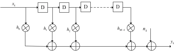
Assume the channel observation at timek is:
yk= M−1
n=0
hnxk−n+nk (2)
where Y = {yk} is information sequence inputted to equalizer, and k is one of 1. . . N, yk is a sampled value at time k, {nk} is AWGN
sequence, X = {xk} is symbol sequence inputted to channel, and M
denotes the memory length of the ISI channel.
k x
k y
0
h
1
h
2
h hM−1 nk
Figure 2. Microwave ISI channel.
The modulation could be in the form of binary phase shift keying (BPSK), where a pulse is modulated with either +1 or−1, so at time
kis: xk∈ {−1,1}. Microwave ISI channel is shown in Figure 2, we can
assume the microwave channel as a convolution encoder with 1 code rate. So the symbol inputted to channel is xk, which the posteriori
defined as follows:
L(ˆxk) =LP OSE (ˆxk) = ln
p(xk= 1/Y) p(xk=−1/Y)
= ln
(s,s),xk=1
p(s, s, Y)
(s,s),xk=−1
p(s, s, Y) (3) and p(s, s, Y) can be expressed as:
p(s, s, Y) =p(s, y1, . . . , yk−1)p(s, yk/s)×p(yk+1, . . . , yN/s)
where:
αk(s) =
s
αk−1(s)γk(s, s)
βk−1(s) =
s
βkγk(s, s)
γk(s, s) = p(s, yk/s) (4)
According to MAP equalization algorithm, γk(s, s) can be
expressed as [2]:
γk(s, s) = exp
− 1
2σ2
ch
yk−
M−1
i=0
hixk−i
2
+1 2xkL
pri E (ˆxk)
(5)
where hi = 1 10(ρi10−ρ1)
, σ2ch =N0/2 is the variance of the noise, and
LpriE (ˆxk) is the a priori information of the coded bitxk. When the M
becomes bigger, the total states of trellis structure will be also big, and it brings about Map equalization algorithm’s increased-complexity. 3.2. Description of the Improved Max-Log-Map
Equalization Algorithm
The Log-Map and Max-Log-Map algorithms are typical and simplified Map equalization algorithms. The Log-MAP algorithm calculates
αk(s), βk−1(s), γk(s, s) in logarithmic terms using the Jacobian
logarithmic function. Using this approach the forward/backward recursion will change to:
αk(s) =max
αk−1(s) +γk(s, s)
where
max(z1, z2) = ln(ez1 +ez2) = max(z1, z2) + ln
1 +e(−|z1−z2|)
(6)
αk(s), βk(s), γk(s, s) represent the logarithmic values of αk(s), βk(s), γk(s, s) respectively. Finally, the soft output maximum a posteriori
log likelihood ratio of the decoder can be determined as follows:
L(xk) = max
(s,s),xk=1
αk−1(s) +γk(s, s) +βk(s)
−
max (s,s),xk=−1
αk−1(s) +γk(s, s) +βk(s)
(7) The Max-Log-MAP algorithm is obtained by omitting the logarithmic part of Equation (6). Using this approximation, the Max-Log-MAP algorithm is suboptimal and gives an inferior performance compared with that of the Log-MAP algorithm. On one hand calculation of the TE-Log-Map algorithm using the Jacobian logarithmic function results in high complexity. On the other hand, saving the results of ln(1 + e(−|z1−z2|)) as different |z
1−z2| value in a lookup table will introduce a quantization error caused by truncation of the input of the lookup table(this truncation is necessary otherwise the size of the lookup table becomes extremely large and the implementation is infeasible), all of those mentioned above increase hardware cost. Moreover, for the calculation of each maximum a posteriori value L(ˆxk) at the output of the equalizer or the decoder,
we have to read the correction terms from the lookup table recursively. Reading data from these tables is a time consuming process and thus it is not desirable. It should be noted that the logarithmic term of Equation (4) is effective when|z1−z2|in Equation (6) is around zero, otherwise the effect of this term is negligible. Therefore MacLaurin series expansion can be employed to describe the logarithmic when
|z1−z2| is around zero. When x = |z1−z2| → 0, MacLaurin series are as follows:
f(x) =
n
k=0 1
k!f
(k)(0)xk+o(|x|n),
So,
ln
1 +e(−x)
≈ln 2−1 2x+
1 4x
2−. . . (8)
Since the logarithmic term of Equation (6) is always greater than zero, we rewrite max( z1, z2) as follows:
max(z1, z2)≈max(z1, z2) + max
0,ln 2−1
2|z1−z2|
Equation (9) can be easily implemented using comparators, adders and a shift register. Therefore, calculation of maximum value in Equation (7) based on Equation (9) is the key to improve algorithm. The improved algorithm’s complexity is close to Max-Log-Map equalization algorithm, but the performance is close to Log-Max-Log-Map equalization algorithm, and is better than Max-Log-Map equalization algorithm.
4. SIMULATION AND ANALYSIS
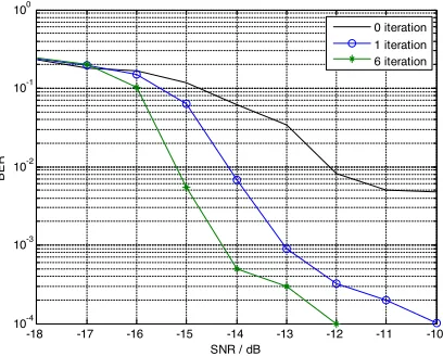
We simulate in following conditions: the microwave multipath fading channel (3 multipaths), BPSK modulation, the carrier frequency is the intermediate frequency after carrying out the DDC, and RSC encoder with 1/2 coding rate, and the interleaver size is 2000. The performances of equalization algorithm including improved Max-Log-Map algorithm, Log-Max-Log-Map algorithm and Max-Log-Max-Log-Map algorithm are shown in Figure 3 and Figure 4. Figure 3 shows that improved Max-Log-Map equalization algorithm performance becomes better obviously as more numbers of iteration are taken, and it can obtain 2 dB gain when BER is about 10−4 after 6 iterations. Figure 4 shows that improved Max-Log-Map equalization algorithm can get more than 1 dB gain compared with Max-Log-Map equalization algorithm, and it is close to the Log-Map algorithm performance. Thereby, the improved algorithm is effective to improve microwave communication with ISI reliability.
-18 -17 -16 -15 -14 -13 -12 -11 -10
10-4 10-3 10-2 10-1 100
SNR / dB
BER
0 iteration 1 iteration 6 iteration
-16 -15 -14 -13 -12 -11 -10 10-4
10-3 10-2 10-1 100
SNR / dB
BER
Max-log-map equalization Improved turbo equalization Log-map equalization
Figure 4. Comparison between Max-log-map, Log-map, and improved Turbo equalization.
5. CONCLUSION
In microwave communications, the channel exists many multipaths, and great multipath time delay difference. When the symbolic transfer rate is high, the equivalent of the channel impulse response will be in great duration and because the complexity of the Map equalization algorithm is increased exponentially with channel memory length and modulation signal constellation size, which will lead to Map equalization algorithm large amount of computation and become unfeasible. The improved Max-Log-Map equalization algorithm’s complexity and performance shown in this paper are compromised, and also it effectively improves the reliability of microwave communication. It can be believed that this algorithm will be more widely used in microwave communication and other similar communication system. ACKNOWLEDGMENT
REFERENCES
1. Dybdal, R. B., “Radar cross section measurements,”IEEE Trans. on Antennas and Propagation, Vol. 75, No. 4, 498–516, 1987. 2. Kent, B. M., “Comparative measurements of precision radar
cross section (RCS) calibration targets,” IEEE Antennas and Propagation Society International Symposium, Vol. 4, 412–415, 2001.
3. Mallahzadeh, A. R., M. Soleimani, and J. Rashed-Mohassel, “RCS computation of airplane using parabolic equation,” Progress In Electromagnetics Research, PIER 57, 265–276, 2006.
4. Knott, E. F., et al., Radar Cross Section, Artech House, Inc., Dedham, MA, 1985.
5. Marquart, N. P., “Experimental anechoic chamber measurements of a target near an interface,” Progress In Electromagnetics Research, PIER 61, 143–158, 2006.
6. Gelius, L. J., “Electromagnetic scattering approximations revisited,” Progress In Electromagnetics Research, PIER 76, 75– 94, 2007.
7. Johnson, R. C., “Compact range techniques and measurements,”
IEEE Trans. on Antenna and Propagation, Vol. 17, No. 5, 568– 576, 1969.
8. Kouyoumjian, R. G., “Range requirements in radar cross section measurements,” IEEE. Proc., Vol. 53, 920–928, 1965.
9. Brumley, S. S., “Extending the low-frequency limits of the compact-range reflector,”IEEE Antennas&Propagation, Vol. 38, No. 3, 81–85, 1996.
10. Censor, D., “Free-space relativistic low-frequency scattering by moving objects,”Progress In Electromagnetics Research, PIER 72, 195–214, 2007.
11. Ott, R. H., “Electromagnetic scattering by buried objects in the HF/VHF/UHF frequency bands,” Progress In Electromagnetics Research, PIER 12, 371–419, 1996.
12. Keller, J. B., “Geometrical theory of diffraction,” J. Opt. Soc. Am., Vol. 52, 116–130, 1962.
13. Attiya, A. M. and E. El-Diwany, “A time domain incremental theory of diffraction: Scattering of electromagnetic pulsed plane waves,”Progress In Electromagnetics Research, PIER 44, 81–101, 2004.
15. Wenher, D. R., High Resolution Radar, Artech House, London, 1987.
16. Teng, L., et al., “High range resolution performance of frequency stepped radar signal,”CIE Inter. Conf. of Radar, 242–245, 1996. 17. Weedon, W. H., “A step-frequency radar imaging system for mi-crowave nondestructive evaluation,”Progress In Electromagnetics Research, PIER 28, 121–146, 2000.
18. Connolly, T. M. and E. J. Luoma, “Microwave absorbers,” U.S. Patent No. 4,038, 660, July 26, 1977.
19. Chung, B. K. and H. T. Chuah, “Modeling of RF absorber for application in the design of anechoic chamber,” Progress In Electromagnetics Research, PIER 43, 273–285, 2003.
20. Chamaani, S., S. A. Mirtaheri, M. Teshnehlab, M. A. Shoorehdeli, and V. Seydi, “Modified multi-objectives particle swarm optimiza-tion for electromagnetic absorber design,”Progress In Electromag-netics Research, PIER 79, 353–366, 2008.
21. Xiao, S. Q., J. Chen, B. Z. Wang, and X. F. Liu, “A numerical study on time-reversal electromagnetic wave for indoor ultra-wideband signal transmission,”Progress In Electromagnetics Research, PIER 77, 329–342, 2007.
22. Plonus, M. A., “Theoretical investigation of scattering from plastic foams,” IEEE Trans. on Antennas and Propagation, Vol. 13, 88–93, 1965.
23. Bracewell, R. N., The Fourier Transform and Its Applications, 2nd edition, McGraw-Hill, New York, 1986.
24. Brigham, E. O.,The Fast Fourier Transform and Its Applications, Prentice-Hall, Englewood Cliffs, NJ, 1988.
25. Talbi, L. and G. Y. Delisle, “Finite difference time domain characterization of indoor radio propagation,” Progress In Electromagnetics Research, PIER 12, 251–275, 1996.
26. Khadem-Hosseinieh, B., Y. Komijani, R. Faraji-Dana, and M. Shahabadi, “Using photon wave function for the time-domain analysis of electromagnetic wave scattering,” Progress In Electromagnetics Research, PIER 76, 397–412, 2007.