3 Phase Induction Motor Control Using Single
Phase Input and GSM
Pooja S.Billade1, Sanjay S. Chopade2
PG Student [VLSI], Dept. of E&TC, SITRC, Nashik, Maharashtra, India1
Associate Professor, Dept. of E&TC, SITRC, Nashik, Maharashtra, India 2
ABSTRACT:This paper focuses on the design of 3 phase induction motor control using single phase input and GSM.The controller used in this work is a wireless speed control using a GSM technique that proves to be very efficient and reliable in applications.The most common principle is the constant V/Hz principle which requires that the magnitude and frequency of the voltage applied to the stator of a motor maintain a constant ratio. By doing this, the magnitude of the magnetic field in the stator is kept at an approximately constant level throughout the operating range. Thus, maximum constant torque producing capability is maintained. The energy that a switching power converter delivers to a motor is controlled by Pulse Width Modulated signals applied to the gates of the power transistors in H bridge configuration. PWM signals are pulse trains with fixed frequency and magnitude and variable pulse width. When a PWM signal is applied to the gate of a power transistor, it causes the turn on and turns off intervals of the transistor to change from one PWM period.
KEYWORDS: PIC, GSM(Global System for Mobile), LCD(Liquid Crystal Display),IM(Induction motor),IGBT(Insulated Gate Bipolar Transistor).
I.INTRODUCTION
Motor drives are used in a very wide power range. In adjustable- speed drive applications the ranges of speed achievable is very important in applications such as c controlling of a boiler feed-water pump. In all drives where the speed and position are controlled, a power electronic converter is needed as an interface between the input power and the motor. A controller is also needed to make the motor, through the power electronic converter, meet the drive requirements. Notably, the extensive automation in modern industries demand several strategies that have high reliability and robust to be introduced and one of the main requirements is the control technique used. The controller used in this work is a wireless speed control using a GSM technique that proves to be very efficient and reliable in applications.
II.SYSTEM ARCHITECTURE
The main single phase supply is rectified by using a diode bridge rectifier. The ripple on the DC bus is filtered by using an electrolytic capacitor. The filtered DC bus is connected to the IGBT-based 3-phase inverter, which is controlled by the PIC16F7X7. The inverter output is a 3-phase, variable frequency supply with a constant voltage-to-frequency ratio. Push button keys are interfaced for issuing commands, like Run/Stop and Fwd/Rev, to the microcontroller. Acceleration and deceleration features are implemented to change the motor frequencies monthly. Times for both of these features are user selectable and can be set during compile time.LEDs are provided for Status/Fault indications like Run/Stop, Forward/Reverse. The PWM outputs are generated by on-chip hardware modules on the PIC16F7X7. These are used to drive the IGBT drivers through optoisolators. Each IGBT driver, in turn, generates complementary signals for driving the upper or lower halves of the 3-phase inverter. It also adds a dead time between their respective higher and lower switch driving signals.
Fig.1: Block Diagram of 1 to 3 phase converter
III. RESULTS AND DISCUSSIONS
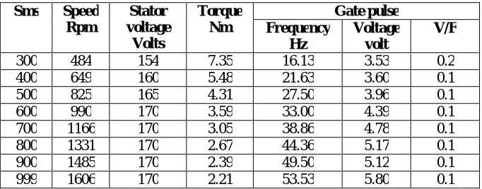
Following table give the idea about speed,voltage,frequency.from that reading I calculate the torque of motor
Table 1: Machine details for three phase 230 volt used in constant V/f control
Sms Speed
Rpm
Stator voltage Volts
Torque Nm
Gate pulse Frequency
Hz
Voltage volt
V/F
300 484 154 7.35 16.13 3.53 0.2
400 649 160 5.48 21.63 3.60 0.1
500 825 165 4.31 27.50 3.96 0.1
600 990 170 3.59 33.00 4.39 0.1
700 1166 170 3.05 38.86 4.78 0.1
800 1331 170 2.67 44.36 5.17 0.1
900 1485 170 2.39 49.50 5.12 0.1
999 1606 170 2.21 53.53 5.80 0.1
Table 2: Machine details for three phase 110 volt used in constant V/f control
Sms Speed
Rpm
Stator voltage
Volts
Torque Nm
Gate pulse
Frequency Hz
Voltage volt
V/F
300 396 133 8.99. 13.2 3.53 0.2
400 583 132 6.10 19.43 3.60 0.1
500 748 130 4.76 24.93 3.96 0.1
600 924 120 3.85 30.8 4.39 0.1
700 1089 120 3.27 36.3 4.78 0.1
800 1243 120 2.86 41.4 5.17 0.1
900 1408 120 2.52 46.9 5.12 0.1
999 1507 120 2.36 50.2 5.80 0.1
The Variable Voltage Variable Frequency drive for a three phase induction motor is successfully developed and tested in laboratory.Test is done on the two test motors.The motor is run at no load .The fundamental voltage reading of the inverter and current readings from two of the phases are recorded as well as the torque output and speed of the motor as follows
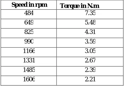
Table 3: Speed –torque values at no load of 3-ph 230 volt.
Speed in rpm Torque in N.m
484 7.35
649 5.48
825 4.31
990 3.59
1166 3.05
1331 2.67
1485 2.39
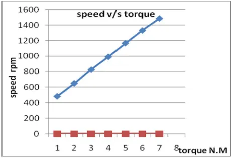
Graph 1: torque v/s speed at no load of 3-ph 230 volt.
The slope of the torque-speed curve may change at the frequencies above the rated frequency
.
Table 4 : Speed –torque values at no load of 3-ph 110 volt
Graph 2: Torque v/s speed at no load of 3-ph 110 volt.
Speed in rpm Torque in N.m
396 8.99.
583 6.1
748 4.76
924 3.85
1089 3.27
1243 2.86
1408 2.52
These changes in torque will change the rotor slip and will impact on the linear relationship between the synchronous speed and the rotor speed as follows
Table 5: speed –torque values at no load of 3-ph 230 volt
Graph3: Speed v/s slip at no load of 3-ph 110 volt
IV. CONCLUSION
In this paper , a low cost and low power consumption wireless speed control of an induction motor is developed and tested for three phase 230 volt and 110 volt.In variable supply voltage control method of speed control, the maximum torque decreases with the decrease of supply voltage and thus the motor remains underutilized. So even this method cannot be used for good performance. In constant control, by use of rectifier and PWM inverter, we can vary the supply voltage as well as the supply frequency such that the ratio remains constant so that the flux remains constant too. So we can get different operating zone for various speeds and torques and also we can get different synchronous speed with almost same maximum torque. Thus the motor is completely utilized and also we have a good range of speed control.
The main role played by GSM which made possible to transmit the readings over the wide distance at very low cost and moderate the data rate.The developed system is very helpful for controlling purposeandSpeed control of motor is acquired with the accuracy of ±15 rpm.Hence this three-phase induction motor V/F control by GSM is more stable, efficient and economical.
Speed in rpm slip
396 0.73
583
748 0.5
924 0.38
1089 0.27
1243 0.17
ACKNOWLEDGEMENT
I offer my thanks to all who have supported and helped me in any respect during the completion of the paper. I am grateful to my guide Prof. Sanjay S. Chopade for giving helpful insights and suggestions during the completion of the paper.
REFERENCES
[1] GSM Based Motor Monitoring and Speed Control’ by V.Bhaskar & T . Gowri Manohar.
[2] Modeling Of Single-Phase To Three-Phase Drive System Using Two Parallel Single-Phase Rectifiers’ by Radha Krishna and Amar kiran proposes a single-phase.
[3] Nalin Kant Mohanty, Ranganath Muthu, ‘Microcontroller Based PWM Controlled Four Switch Three Phase Inverter Fed Induction Motor Drive’ presents PIC microcontroller.
[4] Three Phase Induction Motor Drive Using Igbts And Constant V/F Method”, by M.S.Aspalli, Asha.R, P.V. Hunagund in International ourna of Advanced Research in Electrical, Electronics and Instrumentation Engineering, Vol. 1, Issue 5, November 2012.
[5] Speed Control of 3-Phase Induction Motor Using PIC18 Microcontrollers by Microchip Application Note-843.
[6] VF Control of 3-Phase Induction Motors Using PIC16F7X7 Microcontrollers, by Electrical Engineering by Edward Hughes. [7] Power Electronics by Khanchandani.