Design and Development of Smart Security
System for Bank Using Arm Controller
Pradip S. Bhendwade1, Pravin B. Desai2
Assistant Professor, Dept. of E&TC, Ashokrao Mane Engineering College, Kolhaour, Maharashtra, India1
Assistant Professor, Dept. of E&TC, Ashokrao Mane Engineering College, Kolhaour, Maharashtra, India2
ABSTRACT:Nowadays, all banking sector spending most of its money on security system and it is very important thing. Hence to prevent Banking cash, gold, and all the important legal documents from being stolen, most of the higher banking authorized servants have started using the intelligent smart theft protection systems. Presently available anti-theft systems are very expensive. This paper describes a system, based on ARM 7 microcontroller using some levels of higher security. . It provides a protected password to unlock the first level and real time biometric user authentication in second level to unlock the secured area door after finger print verification is done. If the finger print does not match with that in database , ARM produces the interrupt signal to lock the door and initiates an alarm. The system developed is a simple and economical in providing high security for various applications.
KEYWORDS: Security System, real time, biometric, finger print, authentication.
I.INTRODUCTION
Security is of primary concern and in this busy, competitive world, human cannot find ways to provide security to his confidential things he provide security manually. Instead, of this there is an alternative way by which we can provide a full-fledged security as this system as atomized. In the ubiquitous network society, where individuals can easily access their information anytime and anywhere, people are also faced with the risk that others can easily access the same information anytime and anywhere. Because of this risk, personal identification technology, which can distinguish between this system registered legitimate users and imposters, is now generating interest.
Currently, passwords, Personal Identification Numbers (4-digit PIN numbers) or identification cards are used for personal identification. This system uses cards which can be stolen, and passwords and numbers can be guessed or forgotten. To solve these problems, biometric authentication technology which identifies people by their unique biological information is attracting attention. Biometrics can be defined as recognizing and identifying a person based on physiological or behavioural characteristics. In biometric authentication, an account holder’s body characteristics or behaviours (habits) are registered in a database and then compared with others who may try to access that account to see if the attempt is legitimate. Fujitsu has researched and developed biometric authentication technology focusing on the methods: fingerprints, faces, voiceprints.
RAM. In this this system can store up to 100 user’s fingerprints. This module can operate in 2 modes they are Master mode and User mode. This system will be using Master mode to register the fingerprints which will be stored in the ROM present on the scanner with a unique id.
II.SYSTEM MODEL AND ASSUMPTIONS
In this project the ARM7 controller which forms the heart of the project, plays an important role in establishing communication be this system personal computer and ARM controller. In this proposed system, high level bank security is to be done using password, thumb module, and finally IR sensor for improving quality of security.
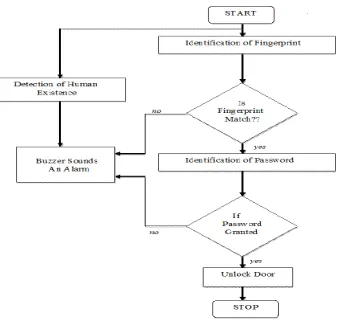
This system, from the study of this project it comes to know that system supplies 12 V dc, 3.5 V dc for ARM processor should be design and then ARM 7 provides supply to all other devices such as keyboard, LCD, relay driver, IR sensor, buzzer etc. The operation is done in four level, the levels are as follows:-1) password level 2) thumb module 3) face recognition 4) IR sensor.
First of all in password level, its input is taken from 4x4 keyboards. In this level if password is granted correctly, same level is satisfied and system proposed the further levels. The next level is a thumb level i.e. the finger print module is FPC1011C. When a person places his finger on the module, it scans his finger print and if he is the first user the module assigns him as master. If another user wants to use this module then he will be regarded as slave. if the scanned image matches with the one stored in fingerprint module memory then the module give a high signal on one pin , i.e. the module indicates a success. Otherwise a high signal will be present on the other pin of fingerprint module, i.e. it indicates a failure (user does not exist). The final level is IR sensor level, in which existence of person will be identified. The identification is done by IR sensor (infrared rays).
If system fails to provide safety at three levels, buzzer will alarm at each respective level. Also buzzer will alarm, if unauthorized person directly enters in higher security zone without crossing all the three levels. In this way, prevention of cash or gold or any important documents from the unauthorized person will be done.
III.THE HARDWARE DESIGN
ARM LPC 2138:
The LPC2131/ 2132/ 2134/ 2136/ 2138 microcontrollers are based on a 32/16 bit ARM7TDMI-S CPU with real-time emulation and embedded trace support, that combines the microcontroller with 32 kB, 64 kB, 128 kB, 256 kB and 512 kB of embedded high speed Flash memory. A 128-bit wide memory interface and unique accelerator architecture enable 32-bit code execution at maximum clock rate. For critical code size applications, the alternative 16-bit Thumb mode reduces code by more than 30 % with minimal performance penalty.
DAC, PWM channels and 47 GPIO lines with up to nine edge or level sensitive external interrupt pins make these microcontrollers particularly suitable for industrial control and medical systems.
The ARM7TDMI-S is a general purpose 32-bit microprocessor, which offers high performance and very low consumption. The ARM architecture is based on Reduced Instruction Set Computer (RISC) principles, and the instruction set and related decode mechanism are much simpler than those of micro programmed Complex Instruction Set Computers. This simplicity results in a high instruction throughput and impressive real-time interrupt response from a small and cost-effective processor core. Pipeline techniques are employed so that all parts of the processing and memory systems can operate continuously. Typically, while one instruction is being executed, its successor is being decoded, and a third instruction is being fetched from memory. The ARM7TDMI-S processor also employs a unique architectural strategy known as Thumb, which makes it ideally suited to high-volume applications with memory restrictions, or applications where code density is an issue.
The key idea behind Thumb is that of a super-reduced instruction set. Essentially, the ARM7TDMI-S processor has two instruction sets:
• The standard 32-bit ARM set. • A 16-bit Thumb set.
RS-232, DB-9 connector and MAX 232:
Information being transferred between system and data processing equipment and peripherals is in the form of digital data which is transmitted in either a serial or parallel mode. Parallel communications are used mainly for connections between test instruments or computers and printers; while serial is often used computers and other peripherals. Serial transmission involves the sending of data one bit at a time, over a single communications line. In contrast, parallel communications require at least as many lines as there are bits in a word being transmitted (for an 8-bit word, a minimum of 8 lines are needed). Serial transmission is beneficial for long distance communications, whereas parallel is designed for short distances or when very high transmission rates are required.
RS-232 cables are commonly available with either 4, 9 or 25-pin wiring. The 25-pin cable connects every pin; the 9-pin cables do not include many of the uncommonly used connections; 4-pin cables provide the bare minimum connections, and have jumpers to provide “handshaking” for those devices that require it. These jumpers connect pins 4, 5 and 8, and also pins 6 and 20. The advent of the IBM PC AT has created a new wrinkle in RS-232 communications. Rather than having the standard 25-pin connector, this computer and many new expansion boards for PC’s feature a 9-pin serial port. To connect this port to a standard 25- pin port, a 9-to-25-pin adaptor cable can be utilized, or the user can create his own cable specifically for that purpose.
The major consideration in choosing an RS-232 cable is, what devices are to be connected First, are you connecting two DTE devices (null modem cable) or a DTE device to a DCE device (modem cable) Second, what connectors are required on each end, male or female, 25-pin or 9-pin.
Usually, it is recommended that the user obtain the two devices to be connected, and then determine which cable is required.
The RS232 pin-out signals are represented by voltage levels with respect to a system common ( logic ground). The "idle" state (MARK) has the signal level negative with respect to common, and the "active" state (SPACE) has the signal level positive with respect to common. RS232 has numerous handshaking lines (primarily used with modems), and also specifies a communications protocol.
The RS-232 interface presupposes a common ground between the DTE and DCE. This is a reasonable assumption when a short cable connects the DTE to the DCE, but with longer lines and connections between devices that may be on different electrical busses with different grounds, this may not be true. RS232 data is bi-polar. The standard specifies a maximum open-circuit voltage of 25 volts, but common signal levels are 5 V, 10 V, 12 V, and 15 V. Circuits driving an RS-232-compatible interface must be able to withstand indefinite short circuit to ground or to any voltage level up to 25 volts. From +3 to +12 volts indicates an "ON or 0-state (SPACE) condition" while A -3 to -12 volts indicates an "OFF" 1-state (MARK) condition. Some computer equipment ignores the negative level and accepts a zero voltage level as the "OFF" state. In fact, the "ON" state may be achieved with lesser positive potential. This means circuit’s supply 5 VDC are capable of driving RS232 circuits directly; the overall range that the RS232 signal may be transmitted / received may be dramatically reduced. The output signal level usually swings between +12V and -12V. The "dead area" between +3v and -3v is designed to absorb line noise
Almost each PC now days equipped with one/two/four serial interface (RS232C). This PC serial port interface is single ended (connects only two devices with each other), the data rate is less than 20 kbps. It's a voltage loop serial interface with full-duplex communication represented by voltage levels with respect to system ground. A common ground between the PC and the associated device is necessary.
RS232 data usually is sent as a packet with 7 or 8 bit words, start, stop, parity bits (may be varied). Sample transmission shown on picture: Start bit (active low, usually between +3v and +15v) follow this system by data bits, parity bit (depends on protocol used) and finished by stop bit (used to bring logic high, usually between -3v and -15v). Serial RS-232 (V.24) communication works with voltages (between -15V ... -3V are used to transmit a binary '1' and +3V ... +15V to transmit a binary '0') which are not compatible with today's computer logic voltages. On the other hand, classic TTL computer logic operates 0V ... +5V (roughly 0V ... +0.8V referred to as low for binary '0', +2V ... +5V for high binary '1' ). Modern low- logic operates in the range of 0V ... +3.3V.
So, the maximum RS-232 signal levels are far too high for today's computer logic electronics, and the negative RS-232 voltage can't at all by the computer logic. Therefore, to receive serial data from an RS-232 interface the voltage has to be reduced, and the 0 and 1 voltage levels inverted. In the other direction (sending data from some logic over RS-232) the low logic voltage has to be "bumped up", and a negative voltage has to be generated, too
IR TRANSMITTER RECEIVER:
The Thumb sets 16-bit instruction length allows it to approach twice the density of standard ARM code while retaining most of the ARMÕs performance advantage over a traditional 16-bit processor using 16-bit registers. This is possible because Thumb code operates on the same 32-bit register set as ARM code. The IR Transmitter Receiver gate this system are using in our project to detect the exact location and position of the vehicle and type of vehicle according to length.
The IR transmitter is continuously emitting the IR rays towards the IR receiver. When the vehicle is going to come across the gate the rays are deflected from the vehicle and IR receiver doesn’t get any signal.
Fig.3.1 IR Transmitter and Receiver Pair
Here as in fig 3.8 it shows IR transmitter and receiver, for IR transmitter this system are using IR LED’s. The IR transmitter this system may design in our home by just connecting desired value of resistance in +ve arm and another is grounded. The IR receiver has three pins i.e. 5V supply, GND. Line, signal line. The IL358 contains two independent high gain operational amplifiers with internal frequency compensation. The op-amps operate over a wide voltage range. The low power drain makes the IL358 a good choice for battery operation.
•
Internally frequency compensated for unity gain. • Large DC voltage gain• Single or Split Supply Operation
• Input common-mode voltage range to ground
Finger Print Sensor (R305) Model:
This is a figure print sensor module with TTL UART interface for direct connections to microcontroller UART or to PC through MAX232 / USB-Serial adapter. The user can store the finger print data in the module and can configure it in 1:1 or 1: N mode for identifying the person. The FP module can directly interface with 3v3 or 5v Microcontroller. A level converter (like MAX232) is required for interfacing with PC serial port.
Optical biometric fingerprint reader with great features and can be embedded into a variety of end products, such as: access control, attendance, safety deposit box, car door locks
Features
Integrated image collecting and algorithm chip together, All-in-one
Fingerprint reader can conduct secondary development; can be embedded into a variety of end products.
Low power consumption, low cost, small size, excellent performance
Professional optical technology, precise module manufacturing techniques
Good image processing capabilities, can successfully capture image up to resolution 500 dpi Specifications
Fingerprint sensor type: Optical
Sensor Life: 100 million times
Static indicators: 15KVBacklight: bright green
Interface: USB1.1/UART(TTL logical level)
RS232 communication baud rate: 4800BPS~115200BPS changeable
Dimension: 55*32*21.5mm
Image Capture Surface 15—18(mm)
Verification Speed: 0.3 sec
Scanning Speed: 0.5 sec
Character file size: 256 bytes
Template size: 512 bytes
Storage capacity: 250
Security level: 5 (1,2,3,4,5(highest))
False Acceptance Rate (FAR) :0.0001%
False Rejection Rate (FRR): 0.1%
Resolution 500 DPI
Voltage :3.6-6.0 VDC
Working current: Typical 90 mA, Peak 150mA
Matching Method: 1: N
IV.THE SOFTWARE DETAILS Keil Micro Vision:
Embedded system means some combination of computer hardware and programmable software which is specially designed for a particular task like displaying message on LCD. If you are still wondering about an embedded system, just take a look at these circuit applications using 8051 microcontroller. You can call these applications embedded systems as it involves hardware (8051 microcontroller) and software (the code written in assembly language).
this system must do certain prerequisite operations with the program. This includes writing the program in assembly language or C language in a text editor like notepad, compiling the program in a compiler and finally generating the hex code from the compiled program. Earlier people used different software’s/applications for all these 3 tasks. Writing was done in a text editor like notepad/WordPad, compiling was done using a separate software (probably a dedicated compiler for a particular controller like 8051), converting the assembly code to hex code was done using another software etc. It takes lot of time and work to do all these separately, especially when the task involves lots of error debugging and reworking on the source code.
Keil Micro Vision is a software which solves many of the pain points for an embedded program developer. This software is an integrated development environment (IDE), which integrated a text editor to write programs, a compiler and it will convert your source code to hex files too.
. Flash Magic:
Introduction
NXP Semiconductors produce a range of Microcontrollers that feature both on-chip Flash memory and the ability to be reprogrammed using In-System Programming technology. Flash Magic is Windows software from the Embedded Systems Academy that allows easy access to all the ISP features provided by the devices. Flash Magic provides a clear and simple user interface to these features and more as described in the following sections. Under Windows, only one application may have access the COM Port at any one time, preventing other applications from using the COM Port. Flash Magic only obtains access to the selected COM Port when ISP operations are being performed. This means that other applications that need to use the COM Port, such as debugging tools, may be used while Flash Magic is loaded.
Flow chart:
V.RESULT AND DISCUSSION
Simulation Result: Observations:
Step1:
Fig 6.1 Initial condition
Step 2:
If authorized person will be their then him/her fingerprint will matches with the registered one and user will crack this thumb level and go for next level, if it is not, then system fails to match fingerprint and system buzzers an alarm
Fig 6.2 First level thumb fingerprinting
Step 3:
As in below fig.6.3 LCD shows “Enter Password” that means thumb detection is done by system and user is identified in first thumb level. so now him/her have to enter registered password, if it granted correctly then and then only door will open otherwise buzzer will again sounds an alarm.
Fig 6.3 Second level entering password
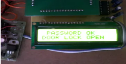
Step 4:
As in below fig.6.3 LCD showing “PASSWORD OK DOOR LOCK OPEN” that means user is a authorized one there is no fake user, as user granted both of levels so door of secured area will open immediately.
VI.CONCLUSION
This system propose it is possible to develop the high level security in banking or any other top secret area by using three levels of operation. The proposed security system also gives space, in terms of hardware and software Fingerprint identification enhances the security of a bank and makes it possible only for some selected people to open the door. Thus by implementing this relatively cheap and easily available system in a bank one can ensure much greater security and exclusivity than that offered by a conventional lock and key.
REFERENCES
[1] S. Chiasson, A. Forget, E. Stobert, P. C. van Oorschot, and R. Biddle, “Multiple password interference in text passwords and click-based graphical passwords,” in Proc. of CCS’09, 2009
[2] Hong-Bo Deng, Lian-Wen Jin, Li-Xin Zhen, Jian-Cheng Huang “A New Facial Expression Recognition Method Based on Local Gabor Filter Bank and PCA plus LDA”, International Journal of Information Technology Vol. 11 No. 11-2005
[3]D. Davis, F. Monroe, L. Coventry.; This systemi, S.S.C.; Yi Song. 2007, “Secure Display and Secure Transactions Using a Handset” IEEE conference on Volume: 60, No: 3.
[4]Professor Marcello Malpighi. of Electro. & Inf. Eng., Shaanxi Univ. of Sci.&Technol.,Xi'an,China Jia Mi .2010“ATM terminal design based on finger print recognition” IEEE conference on Volume: 1, No:3.
[5]Rood and Horned,R.A. Inf. Techno., Kalasalingam Univ., Virudhunagar,India Rajalakshmi, R. 2012 “Shape to maintain the ATM system stability” IEEE conference on Volume: 10.
[6] Rashid, R.A. Dept. of Telecomm. & Opt., Univ. Techno. Malaysia, Skudai Mahalin, N.H. ; Sarijari, M.A. ; Abdul Aziz, A.A. 2008 “Security system using biometric technology: Design and implementation of Voice Recognition System (VRS)” IEEE conference on Volume: 8.
[7]Yang and Verbauwhede, . of Comput. Technol., Chinese Acad.of Sci.,Beijing Yanmin Zhu ; Li Cui ; Ni, L.M. 2009 “FKM: A Fingerprint-Based Key Management Protocol for SoC-Based Sensor Networks” IEEE conference on Volume: 5.
[8]Dr. David Chaum, CEO of DigiCash Chaum "Untraceable Electronic Mail, Return Addresses, and Digital Pseudonyms", laid the groundwork for the field of anonymous communications research.
[9]Introduction to Image Processing and Analysis by John C. Russ (Author), J. Christian Russ (Author)
BIOGRAPHY
Prof. Pradip S. Bhendwade received the M. Tech in Electronics and currently working as Assistant Professor in Ashokrao Mane Group of Institute, Vathar, and Kolhapur. His area of specialization is Embedded Systems, Microprocessor and Microcontroller, Control System.